Variable Parameter Resized Zero Attracting Least
Mean Fourth Control for Grid-Tied PV System
Md. Ibrahim, M.A. Mallick, Mukul Chankaya, Atif Iqbal, Ikhlaq Hussain
.
Abstract: This paper presents the variable parameter resized zero attracting least mean fourth (VP-RZA-LMF) control algorithm for grid-tied photovoltaic (PV) system. The proposed control algorithm is superior over the conventional control algorithms in terms of swift response and handling the irregular nature of solar irradiations. The DC bus voltage control is incorporated in voltage source converter (VSC) control. The boost converter utilizes the maximum power point tracking (MPPT) algorithm for producing its gating sequence to keep PV array voltage constant.
Keywords—Photovoltaic (PV), grid-tied, variable parameter resized zero attracting least mean square (VP-RZA-LMS)
I. INTRODUCTION
The modern power system is facing new challenges day by day, with the rapidly growing demand for power. The fossil fuel-based power generation has been adding up to environmental concerns like increasing carbon footprint and green-house gases emissions. which cause global warming, acid rain, and depletion of the ozone layer [1]. It is necessary to induct new power generation sources along with coal operating the power plant due to depleting fossil fuel reserves. The solar thermal, Photovoltaic (PV), tidal, wind, and biomass are few of the matured renewable power generation technologies. The PV systems are gaining popularity [2] over other non-conventional power generation resources due to its simple operation and ease of installation unlike solar thermal, wind and geothermal plants. The PV system can penetrate the conventional grid at almost any scale ranging from few kW rooftop plants to 10's of MW ultra mega PV plants [3]. With technological advancements, the cost of the PV system has become very affordable to individuals, unlike thermal solar and wind power plants that need huge investment and special skills to install. Countries like the US, China and India [4] are leading the world in promoting the PV system as a viable option for providing the required power. The PV system with a conventional grid can overall reduce carbon footprint along with the greenhouse gasses emission.
The PV system may be integrated into the grid via a single-stage or dual-stage topology. In single-stage topology, the PV system is directly connected to DC bus, whereas, in dual-stage boost, the converter is utilized in between PV and voltage source converter (VSC) [5].
Revised Manuscript Received on September 06, 2019
Md. Ibrahim, Electrical Engineering Department, Integral University, Lucknow, India. [email protected]
Mukul Chankaya, Electrical Engineering Department, Kashmir University, Srinagar, India. [email protected]
Ikhlaq Hussain Electrical Engineering Department Kashmir University, Srinagar, India. [email protected]
M.A. Mallick, Electrical Engineering Department, Integral University, Lucknow, India. [email protected]
Atif Iqbal, Electrical Engineering Department, Qatar University, Qatar.
The dual-stage topology of grid integration is beneficial and efficient for a system having DC voltage (𝑉𝐷𝐶) < 750 V.
Many maximum power point tracking (MPPT) algorithms are mentioned in the literature to extract maximum power from the PV system [6]. Due to variation in irradiation level and ambient temperature the operating point keeps on changing from maximum power point (MPP).
Several VSC control has been mentioned in literature and can be categorized in terms of conventional, adaptive and intelligent controls i.e. unit template, synchronous reference frame (SRF), Least mean fourth (LMF), direct power control, discrete Fourier transform, droop control and artificial intelligence (AI) based technique[7]. Which are unilized to mitigate the power quality problems.
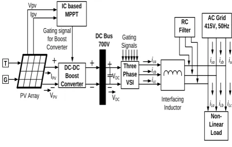
PV Array T G DC-DC Boost Converter DC Bus 700V Three Phase VSI Gating Signals Interfacing Inductor AC Grid 415V, 50Hz Non-Linear Load IC based MPPT Gating signal for Boost Converter Vpv Ipv RC Filter
isa isb isc
IPV
VPV
icb
ica
icc
iLa iLb iLc
[image:1.595.306.544.324.475.2]VDC VDC
Fig. 1. Block diagram of the proposed topology
The proposed system presents a 3-phase 3-wire grid-tied
dual stage PV System [8] simulated in
MATLAB/SIMULINK environment. The controls are provided for boost converter and VSC. The main contributions of the proposed system are
a. The dual-stage PV system provides constant DC link voltage irrespective of irradiation and temperature variation.
b. The VSC perform a multi-functional operation for mitigating power quality issues
c. The VSC control is provided by a variable parameter re-sized zero attracting least mean fourth (VP-RZA-LMF) [9] algorithm for its better and faster response due to less mean square error (MSE).
II. PROPOSED TOPOLOGY
The 𝑉𝐷𝐶 is maintained constant across VSC with the help of
the capacitor. The VSC perform the harmonics suppression, load balancing and voltage regulation with the proper switching sequence at the point of common coupling (PCC). The interfacing inductance (𝐿𝑖𝑛𝑡) and RC filter are utilized
for eliminating the voltage and current ripples generated by the non-linear load.
III. CONTROL STRATEGY
The proposed control scheme is consist of MPPT and VSC control. The VSC control is shown in Fig.2. The VP-RZA-LMF is an adaptive control algorithm that reduces the excess mean square error (EMSE) by varying the size of the parameter in each iteration.
+
_
Vt= sqrt(2/3(Vsa2 + Vsb2+ Vsc2))
x
/
PPV 2/3 Wsp+
+
+
iLa uPaL P F 1/3 Wsa(n+1)
Extraction of phase b
‘Wsb’ component
Extraction of phase c ‘Wsc’ component
iLb
iLc
uPb
uPc
Wsb(n+1)
Wsc(n+1)
Isa*
Isb*
Isc*
Current Error Extraction
Isa IsbIsc
Hysteresis Current Controller Gating Pulses to VSC Wp
Vsa Vsb Vsc
WPV
Extraction of phase a
‘Wsa’ component
𝑾𝒔𝒂 𝒏 + 𝟏 = 𝑾𝒔𝒑+ 𝝁𝒏∗ 𝒆𝒏𝟑∗ 𝝁𝒑𝒂− 𝝆𝒏∗
𝐬𝐠𝐧{𝐖𝐬𝐩} 𝛆 + |𝐖𝐬𝐩|
𝒆𝒏 𝒏 = 𝒊𝑳𝒂 𝒏 − 𝝁𝒑𝒂 𝒏 ∗ 𝑾𝒔𝒑
𝑰𝒔𝒂∗= 𝑾𝒔𝒑∗ 𝝁𝒑𝒂
Fig.2.Voltage source converter
A. MPPT Control
The MPPT based on IC algorithm senses the instantaneous PV voltage (𝑉𝑃𝑉)and PV current (𝐼𝑃𝑉). The
(1),(2) & (3) govern the IC algorithm are described below. Where „e‟ is the error tolerance which ideally should be zero and D is the duty cycle[11].
𝑑𝐼𝑃𝑉
𝑑𝑉𝑃𝑉+
𝐼𝑃𝑉
𝑉𝑃𝑉 = 𝑒; at MPP; D optimized (1)
𝑑𝐼𝑃𝑉
𝑑𝑉𝑃𝑉+
𝐼𝑃𝑉
𝑉𝑃𝑉 > 𝑒; D increases (2)
𝑑𝐼𝑃𝑉
𝑑𝑉𝑃𝑉+
𝐼𝑃𝑉
𝑉𝑃𝑉< 𝑒; D decreases (3)
The D is further compared with the triangular signal of 10 kHz to provide the gating signals for the boost converter. Which maintains the (𝑉𝑃𝑉) constant irrespective of
irradiation and ambient temperature variation.
B. VSC Control
VSC control is shown in Fig. 2. The error (𝑒𝑛)is
calculated as per (4), where the load current of phase ‟a‟ (𝑖𝐿𝑎), the unit template of phase „a‟ (µpa) and feedback
weight component (𝑊𝑠𝑝) as per (10) of the proposed control
are utilized. The feed forward term of the PV system (𝑊𝑃𝑉)
is calculated as per (5), using the sensed phase voltages of the source(𝑉𝑠𝑎, 𝑉𝑠𝑏 & 𝑉𝑠𝑐) and power supplied by the PV
system(𝑃𝑃𝑉). The extracted weight component of each
phase (𝑊𝑠𝑎, 𝑊𝑠𝑏 & 𝑊𝑠𝑐) are calculated [12] as per (6),(7) &
(8), where μnis the positive step size chosen for stabilizing
the system, ρn is the shrinkage parameter and ε is the
scaling factor. The average weight component (𝑊𝑝) is
calculated as per (9). The reference current signals
(Isa∗ , Isb∗ , Isc∗) are calculated as per (11) and further negated
with sensed source currents of each phase (𝐼𝑠𝑎, 𝐼𝑠𝑏, 𝐼𝑠𝑐) to
generate the VSC gating pulses utilizing hysteresis current controller.
en = iLa− µpa∗ Wsp (4)
WPV = 2
3
PPV
2
3 Vsa2 +Vsb2 +Vsc2
(5)
Wsa n + 1 = Wsp + μn∗ en3∗ μpa− ρn∗
sgn {Wsp }
ε+|Wsp| (6)
Wsb n + 1 = Wsp+ μn∗ en3∗ μpb − ρn∗
sgn {Wsp } ε+|Wsp| (7)
Wsc n + 1 = Wsp+ μn∗ en3∗ μpc − ρn∗
sgn {Wsp }
ε+|Wsp| (8)
𝑊𝑝= 1 3 𝑊𝑠𝑎+ 𝑊𝑠𝑏+ 𝑊𝑠𝑐 (9)
𝑊𝑠𝑝= 𝑊𝑝− 𝑊𝑝𝑣 (10)
Isa∗ = 𝑊𝑠𝑝∗ µpa; Isb∗ = 𝑊𝑠𝑝∗ µpb; Isc∗ = 𝑊𝑠𝑝∗ µpc (11)
C. Selection of DC bus voltage and capacitor
The 𝑉𝐷𝐶 are calculated as per (12).
𝑉𝐷𝐶 =2 2 ∗ 𝑉𝐿𝐿
3 ∗ 𝑚
(12)
Where m is the modulating index considered as unity (m=1)
and 𝑉𝐿𝐿 is the source line voltage. DC bus capacitor 𝐶𝐷𝐶
can be calculated as per (13w).
1
2𝐶𝐷𝐶 𝑉𝐷𝐶
2 − 𝑉
𝐷𝐶1
2 = 3𝐾
1∗ 𝑉𝑠𝑎∗ 𝑎 ∗ 𝐼 ∗ 𝑡 (13)
Where 𝑉𝐷𝐶 is the nominal voltage, 𝑉𝐷𝐶1 is the minimum
voltage level, „a‟ is overloading factor, „𝑉𝑠𝑎‟ is the phase
voltage and „t‟ is the time within which 𝑉𝐷𝐶 should be
recovered[13].
IV. SYSTEM PERFORMANCE
The proposed system has 32 kW of PV system incorporated. The PV power (PPV) is supplied to the grid
via boost converter. The non-linear load of 15.5 kW is simulated at the load end. The source voltage is 415 V (rms) at 50 Hz. The system is operated under steady-state and dynamic state i.e. varying insolation and load unbalancing conditions.
A. Steady-State Performance
During steady-state operation, the solar insolation level is kept at 1000 𝑊 𝑚2 and temperature at 25°celsius. The total
harmonics distortion (THD) of source voltage, source current and load current are shown in Fig. 3(a),(b) & (c), which are satisfactory as per IEEE 519 standards. The source voltage(𝑉𝑠𝑎𝑏𝑐), source current (𝑖𝑠𝑎𝑏𝑐), load current of phase
„a‟ (𝑖𝐿𝑎) compensator current of phase „a‟ (𝑖𝐶𝑎), active and
reactive power supplied to the grid (𝑃𝑔 & 𝑄𝑔) are shown in
The presented system maintains the unity power factor (UPF) throughout the operation. The 𝑉𝐷𝐶 is maintained at
700 V. The 𝑃𝑔supplied to the grid is around 15 kW and 𝑄𝑔is
zero during steady-state operation.
(a)
(b)
(c)
Figs.3.(a),(b) & (c) Harmonic content of (a) 𝐢𝐬𝐚 (b) 𝐯𝐬𝐚 and (c) 𝐢𝐋𝐚 during steady-state
(a)
(b)
Figs 4. Steady-state performance of (a) 𝐯𝐬𝐚𝐛𝐜𝐢𝐬𝐚𝐛𝐜, 𝐢𝐋𝐚, 𝐢𝐂𝐚, 𝐏𝐠 & 𝐐𝐠 (b) 𝐕𝐏𝐕, 𝐈𝐏𝐕, 𝐏𝐏𝐕 & 𝐕𝐝𝐜
B. Dynamic-State Performance with Varying Irradiation
During dynamic-state operation the solar irradiation level changes from 600 𝑊 𝑚2 to 1000 𝑊 𝑚2 at 0.6 sec of
simulation time. The 𝑃𝑔 changes from few hundred watts to
15 kW as irradiation level increases. The system maintains the UPF between𝑣𝑠𝑎𝑏𝑐 & 𝑖𝑠𝑎𝑏𝑐 while maintaining the 𝑄𝑔at
zero as shown in Fig. 5(a). The 𝑉𝑃𝑉 & 𝑉𝑑𝑐 are maintained at
The corresponding change in 𝐼𝑃𝑉 & 𝑉𝑃𝑉 are shown in
Fig. 5(b).
(a)
(b)
Figs. 5. Dynamic-state performance under varying solar irradiations of (a) 𝐯𝐬𝐚𝐛𝐜𝐢𝐬𝐚𝐛𝐜, 𝐢𝐋𝐚, 𝐢𝐂𝐚, 𝐏𝐠 & 𝐐𝐠 (b) 𝐕𝐏𝐕, 𝐈𝐏𝐕, 𝐏𝐏𝐕 & 𝐕𝐝𝐜
C. Dynamic-State Performance under Load Unbalancing
During dynamic-state operation load of phase „a‟ is detached from the grid to create the load unbalancing. The
𝑖𝐿𝑎 remains zero till 0.5 sec of the simulated time and then
returns to balanced load condition as shown in Fig. 6 (a). During which the VSC provides the 𝑖𝐶𝑎to maintain the
balance of the system. The unbalancing has no effect on the DC side of the system as 𝑉𝑃𝑉, 𝐼𝑃𝑉, 𝑃𝑃𝑉 & 𝑉𝑑𝑐 maintains the
same state as in steady-state operation as shown in Fig. 6 (b). The weight components of the corresponding unbalanced system are shown in Fig. 7. Where the change in
𝑊𝑝, 𝑊𝑠𝑝are noticeable from unbalanced to balanced load.
(a)
(b)
Fig.7. Dynamic-state performance under load unbalancing of
µ𝐩𝐚, 𝐈𝐬𝐚, 𝐖𝐬𝐚, 𝐖𝐏, 𝐖𝐏𝐕 & 𝐖𝐬𝐩
V. CONCLUSION
The 3-phase 3-wire grid-tied PV system with VP-RZA-LMF adaptive control algorithm has been proposed. The system performance has been analyzed under steady-state and dynamic-state conditions. The 𝑣𝑠𝑎𝑏𝑐, 𝑖𝑠𝑎𝑏𝑐 are in phase
opposition as power is being transferred to the grid from the PV system while maintaining the UPF. The THD of the presented system during steady-state has been well below 5% and accepted as per IEEE 519 standards. The system behavior is found satisfactory under varying irradiation and load unbalancing conditions. The exchange of 𝑄𝑔 of grid
and PV system is kept zero throughout the operation.
VI. ACKNOWLEDGMENT
I am very thankful to Prof. Mohd. Arifuddin Mallick ,Dr Ikhlaq Hussain and Mr Mukul Chankaya for inspiring me to model and simulate it as simulation on MATLAB/Simulink. I am thankful to Integral University for registering my manuscript MCN: IU/R&D/2019-MCN 000706.
APPENDIX
System Parameters: The PV module voltage, 𝑉𝑚𝑝𝑝=26.3 V;
PV module current, 𝐼𝑚𝑝𝑝=7.614 A; no. of parallel module,
𝑛𝑝=7; no. of series module, 𝑛𝑠=23; PV array voltage,
𝑉𝑝𝑣=605 V; PV array current, 𝐼𝑝𝑣=53.29 V; PV array power,
𝑃𝑝𝑣=32 kW; boost inductor, 𝐿𝑏=3.11 mH; DC link capacitor,
𝐶𝑑𝑐= 10000 µF; DC link voltage PI control, 𝐾𝑃𝑑𝑐= 1 and
𝐾𝑖𝑑𝑐 =0; 𝑉𝑑𝑐 =700 V; VSC = 35 kVA; adaptive filter
constant, µn =0.01, ρn =0.006 & ε=0.002; interfacing
inductance, 𝐿𝑖𝑛𝑡=4 mH; 3-phase grid voltage, 𝑉𝑠𝑎𝑏𝑐= 415 V
(rms); RC filter, 𝑅𝑓=10 Ω and 𝐶𝑓=10 µF; 3-phase non-linear
load = 15.5 kW, sampling time, Ts= 10 µs.
REFERENCES
1. U. Aswathanarayana, Solar energy. Elsevier Inc., 2010. 2. E. Kabir, P. Kumar, S. Kumar, A. A. Adelodun, and K. H. Kim,
“Solar energy: Potential and future prospects,” Renew. Sustain. Energy Rev., vol. 82, no. September 2017, pp. 894–900, 2018. 3. M. Rathbun, Y. Xu, R. R. nejad, Z. Qu, and W. Sun, “Impact
Studies and Cooperative Voltage Control for High PV Penetration,” IFAC-PapersOnLine, vol. 51, no. 28, pp. 684–689, 2018.
4. V. A. Suryad, S. Doolla, and M. Chandorkar, “Microgrids in India: Possibilities and challenges,” IEEE Electrif. Mag., vol. 5, no. 2, pp. 47–55, 2017.
5. A. K. Singh, I. Hussain, and B. Singh, “Double-Stage Three-Phase Grid-Integrated Solar PV System With Fast Zero Attracting Normalized Least Mean Fourth Based Adaptive Control,” IEEE Trans. Ind. Electron., vol. 65, no. 5, pp. 3921– 3931, 2018.
6. N. Karami, N. Moubayed, and R. Outbib, “General review and classification of different MPPT Techniques,” Renew. Sustain. Energy Rev., vol. 68, no. September 2016, pp. 1–18, 2017. 7. N. Beniwal, I. Hussain, and B. Singh, “Hybrid VSS–LMS–LMF
based adaptive control of SPV-DSTATCOM system under distorted grid conditions,” IET Renew. Power Gener., vol. 12, no. 3, pp. 311–322, 2017.
8. N. Saxena, B. Singh, and A. L. Vyas, “Integration of solar photovoltaic with battery to single-phase grid,” IET Gener. Transm. Distrib., vol. 11, no. 8, pp. 2003–2012, 2017.
9. D. Jin, J. Chen, C. Richard, and J. Chen, “Model-driven online parameter adjustment for zero-attracting LMS R,” Signal Processing, vol. 152, pp. 373–383, 2018.
10. A. Nicastri and A. Nagliero, “Comparison and evaluation of the PLL techniques for the design of the grid-connected inverter systems,” IEEE Int. Symp. Ind. Electron., pp. 3865–3870, 2010. 11. N. Saxena, I. Hussain, B. Singh, and A. L. Vyas,
“Implementation of a Grid-Integrated PV-Battery System for Residential and Electrical Vehicle Applications,” IEEE Trans. Ind. Electron., vol. 65, no. 8, pp. 6592–6601, 2018.
12. M. Jiang, W. Liu, and Y. Li, “Adaptive Beamforming for Vector-Sensor Arrays Based on a Reweighted Zero-Attracting Quaternion-Valued LMS Algorithm,” IEEE Trans. Circuits Syst. II Express Briefs, vol. 63, no. 3, pp. 274–278, 2016. 13. B. Singh, A. Chandra, and K. Al-haddad, Power Quality