Abstract: The aftereffects of modelling and the investigation of the aluminium (Al) and aluminium based (Al6061) silicon carbide reinforcement (SiCp) Metal matrix composite (MMCs) during milling is analysed. The impact of processing parameters, for example, speed, feed rate, depth of cut on tool wear and the cutting forces has been examined. The analysis of the cutting forces in the milling of Al and its MMC plays an important role in characterizing the cutting operations through the response surface methodology (RSM) forecast model. The predicted model used to decide the consolidated impact of machining parameters on the cutting forces (Cf) and tool Flank
wear (Vbmax.). The consequences of the model were contrasted with the experimental results and observed that the effects of the forecast help in the evolution of process parameters to minimizing the Cf and Vbmax.
Index Terms: Milling, Aluminium MMC, cutting forces and tool Flank wear.
I. INTRODUCTION
Aluminium based metal matrix composites (ALMMCs) has numerous advantages over different materials, including a high quality to weight proportion, corrosion/erosion resistance, formability and finally cost. Different class of Al 6061, Al 7075 and Al 2024 come across in a different group of "Aviation Alloys" for their functional applications in the Aerospace. Plane wing parts, Engine turbine blades and other complex parts of the plane are some common list of the subcomponent’s that was fabricated by the ALMMCs [1]. Proposed composites are designed to be light-weight and solid, and their simplicity of formability permits complex shapes and drawn parts[2], which would then be able to be additionally improved with heat-treatment. Aluminium AL6061/T6 and ALMMCs is a compound which contains magnesium and silicon as major alloying components. It has been a normal composite which is utilized for some reasons since it has the predominant mechanical properties, for example, hardness and great weldability [3]. This is expected to solutionize and tempered review that has a place with this
Revised Manuscript Received on July 08, 2019.
Ankush Kohli, Research Scholar Mechanical Engineering, IKGPTU, Jalandhar, India.
H. S. Bains, Dept. of Mechanical Engineering, PUSSGIRI, Hoshiarpur, India.
Sumit Jain, Dept. of Mechanical Engineering, CTIEMT, Jalandhar, India.
kind of aluminium.
The famous applications for this sort of material are in the automotive industry, aircraft, and defence/ satellite industry. The ability of the numerical control milling machine to make confounded unique/difficult shape would be an important favourable advantage for AMMCs. Notwithstanding, the interest for consideration at first glance is the condition and the nature of the product, particularly the surface roughness of the fabricated surface, in view of its impacts on part appearance, reliability and its functionality [4], [5]. So, there is a necessity for developing the unique mechanistic model for the prediction of the cutting forces and the tool wear during the milling of the aluminium based metal matrix composites (AMMCs). The cutting forces during machining of Al and AlMMC are low as compared to another different alloy under the same machining conditions. It nevertheless provides a good indicator [6].
Cutting forces are one of the fundamentally imperative in machining operations [7], [8]. It helps comprehension of basic machining characteristics like surface accuracy, machinability, tool wear, power consumption, tool life and cutting temperature. Cutting forces generally impacted by material property like hardness, tool geometry, machining conditions. By investigating the cutting forces by closely observation between tool and cutting materials is advantageous to accomplish an exact advancement of the machining process.
A few studies have been found to inspect the effectiveness of various cutting tools like coated/uncoated carbide and other famous cutting-tools amid the machined of MMCs materials. The basic problems while machining ALMMC is the chipping in the tool flank wear affected by the solid and abrasive reinforcement. Manna. et al. explored the machined of AlSiCMMC and examined that
Built-up edge (BUe) is not framed while machining of AlSiCMMC at peak Spindle speed and low DOC and furthermore obtained a superior surface-rougness at high speed, low feed rate and low DOC [9]. Kevin Chou and Jie Liu investigated the machining of AlSic/MMC by using CVD tool and explored the temperature, tool wear and the cutting forces. The result showed that speed and the feed rate were more affected by the tool wear and no better results obtained from the coated tool
because of enhancing the wear
Modelling and Optimization of Cutting
Forces and Tool Wear in Milling of Aerospace
Al 6061(Sic) Composites
at higher temperature [10]. Tao Wang et al. showed a FEM-model for a higher number of Si/C particles and Al-matrix for milling of Al/Si/Cp MMC. In the study, two different types of the particle were taken under taken, one is circular and other is a polygon. Cutting-force fluctuation was quite higher in the polygon type as compared with circular and often two types of defects found one is a small cavity that
[image:2.595.186.544.160.447.2]is due to pulled out particles and other is big discontinue cavity due to particle moved and rotated inside the matrix [11]. Davim et al. explored the various machining parameters with cutting tool wear and stated that errors associated with the tool wear and force are quite high as compared with the power transmitted by using the
Table 1 Chemical Composition of AL6061/Sicp by Weight Percentage
Particulate Si Fe Cu Mn Mg Cr Zn Ti Ni
AL6061/Sicp 2.51 0.29 .032 .03 2.5 0.018 0.044 0.022 0.014
New carbide inserts face is used during performing of each cut in the part and new different region along a surface line having 115 mm is taken. To find the accurate force value Kistler dynamometer is used and digital Mitutoyo tool maker microscope was used for measuring Vbmax., an average of three measurements was used as a response. Today there is a tremendous number of carbide inserts were available according to the geometric shapes, simple as square, triangular and rhombus. Now inserts manufacturer used such styles frustum, elliptical and helical to describe the different size/shapes and moreover the purpose of such design is just trying to reducing the Cf and Vbmax. In this experiment a
triangular milling insert is used for the milling of AL6061/Sicp Composites having nose radius is 0.4 mm as shown in the figure.1. A Systematics diagram for Aluminium 6061, Silicon carbide powder, casting with a stirrer, final plates after casting, taguchi techniques with orthogonal array [12].
II. MATERIALS AND METHODS
For the experiment, fabrication of rectangular plate (115x50x35 mm) for AL6061/Sicp Metal Matrix Composites through Stir casting. Firstly, Aluminium is preheated to a temperature of 4500c further heated in the main furnace up to 9000c and then mixing the silicon and magnesium metal in powder form each by 2.5 percentages by weight for improving wettability and fluidity of the AL6061/Sicp MMC. After that pouring SiCp particle having mesh size is 220 mm in the molten aluminium in a graphite crucible and a successful vortex is generated through a graphite rod stirrer having 450 rpm for 25 minutes and then pouring in the metal die. The final plate having dimension is (115x48x34 mm) by providing a rough cut. In this experiment, powerful and flexible CNC vertical milling machines (Milling HUNCO VM10) have used for the Milling of AL6061/Sicp Composites under dry conditions. The Chemical composition of AL6061/Sicp is as shown in table 1
microstructure and milling inserts are shown in figure 1.
Fig. 1 Systematic Arrangement Of Material, Reinforcement, Experiment Setup And Tooling Inserts.
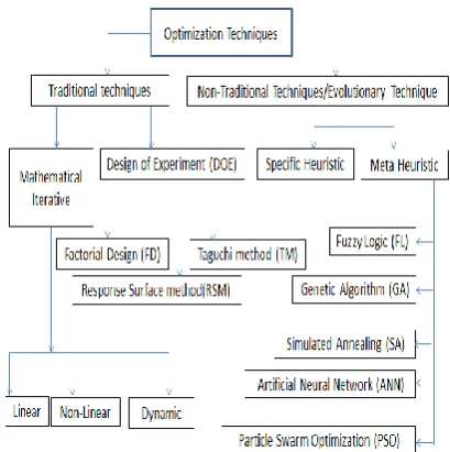
III. OPTIMIZATION METHODS
Fig. 2 Traditional And Non-Traditional Optimization Techniques
The literature reported that non-traditional optimization methods, for example, ANN, FL,GA
and Pso to optimize variables have been applied in the conventional machining because of prone to manage exceedingly nonlinear, multidimensional and on complex designing problems [14]. Conventionally selection of process parameters was based on the manufacturer engineer of their experiences or judgement. But passage of the time with complexity in the metal cutting, researchers substantially focused on the non-traditionally techniques of optimization with respect to the various process parameters [13]. Most literature has tended to machine economies by methods for different optimization techniques. Shin and Joo selected a blend of two conventional optimization methods. Gupta.et al. decided the ideal machining variable.by.an optimization integrated way in light of mixed linear and geometric programming [15], [16]. All the previously mentioned examinations were produced ignoring an extensive segment of different process variables that, rather, result incorporated into other existing numerical solutions of the milling. The above customary techniques have certain disadvantages, for example, closeness to local level minima and high complex calculations prerequisites and even not viable when the objective is multi-mode. Artificial technique have gotten a fixed measure of consideration with respect to their potential for understanding successfully an extensive variety of tough optimization issues, from single to multiple non-linear parameters limitations [17]. GA and SA are ground breakings in seeking an expansive solution space with a multi-mode function with other parameters [18]. Pso methodology was presented by Kennedy and.Eberhart to take care of optimize the process variables. The swarm is made out of the huge volume of particles with stochastic speeds, every one of which speaks to a plausible arrangement. The Pso algorithm finds the ideal arrangement for moving the particles in the set space. The Pso is a productive option over other stochastic and population-based evolutionary algorithms, particularly when managing with a number of different variables in optimization. It is generally simple to
execute and has fewer parameters to alter when contrasted with other artificial techniques. In our experimentation, a Pso is used to optimize different machined parameters like speed, feed and depth of cut in milling operation and compare with the RSM.
IV. BASIC PSO ALGORITHMS
Pso is like the evolutionary technique in that the framework is presented with a populace ("swarm") of irregular arrangements. Each optimum solutions called as flies-Particle in the x-dim. space is equitable by the flying knowledge of the discrete and its identifier. Later, scientist has investigated a few models of Pso technique. Each particle is refreshed amid emphasis with a specific velocity, implement the two ''Best'' values. Firstly, p-best is related to the best position from the whole swarm and secondly; g-best is the best particle-position in the whole swarm. On-off chance that the particle wants the best position by the iteration process outperforms the worldwide best; at that point, the p-best position consequently gets supplanted by the g-best position based on the accompanying condition. We utilize the global-model conditions are depicted as takes after [26]:
Sid is the ith. Particle-velocity, Position represents by Xid,
the local best-solution is P.id – also known as “p.Best”, and
also the global best solution is represented by all particles in the populace. “ is inertia-weight. & : weight of the stochastic-acceleration expression towards “p-Best”& “g-Best” location. Rand ( ) & rand ( ): random functions having limits {0,1}. For experiment optimization, the weighing inertia is fixing to the equation’s.
Wmax: starting weighing coefficient, Wmin: final weighing
coefficient, itermax: maximum generation and iter: current
generation.
V. DESIGN OF EXPERIMENT (DOE)
The machining experiments involved with uncoated carbide inserts and conducted at varied sets of cutting parameters under dry cutting conditions as shown in the table2. The cutting speed was in the range of 250- 500 m/min., feed rate (0.2–0.6mm) and radial depth of cut (1 mm–2.0mm). The axial depth of cut was maintained constant at 08 mm. With the cumbersome of the calculations in approximation functions, it is a necessity to the implementation of the design of experiment by conventional and non-conventional optimization techniques for the objective of to ease in process variables. In design expert software, it is possible by the method of response surface design to optimize the process variables by formulating an
[image:3.595.55.260.52.258.2]typically best recommended for the first and second order non-sequential problems. Box-Behnken design is less expensive and lesser time consuming as compared with the central composite design because of it have fewer design points. Box-Behnken design doesn’t have axial points by keeping all the data points in the safe zone and hence safe. Box Behnken plans likewise guarantee that all variables are never set at their high level at the same time. A three level of Box-Behnken design in response surface approach was carried to find the optimum machining parameters for measuring (Cf) and Vbmax.
Table 2 Various Machining Parameters And Apparatus Machine Milling HUNCO VM10
Inserts Widea , nose radius 0.4 mm
Cutting parameters
Speed : 250, 375 and 500 m/min. Feed rate: 200,300 and 400 mm/min. and DOC: 1.0,1.5 and 3.0 mm For
Measuring Cutting Forces and Tool wear
kistler dynamometer, Digital Mitutoyo toolmaker microscope
The considered improvement needs definite input variables for giving ideal outcomes. The different values for solving the Pso problem are depicted in Table 3. The direct
diminishing Inertia Weight & Learning Rates { & } have a basic influence in the effective and triumphant algorithm. It gives proper balance amongst globally and locally inquiry to be directed by particles. Beginning weighing value permits quick investigation of search domain while dynamically diminishing inertia weight in the later stage takes into consideration through local search, in this way upgrading exactness of calculation. Correspondingly, learning rates are linearly expanded to quicken the particles speed towards local & global-best position according to the accompanying condition.
C min. & c max. : minimum and maximum learning-rate &
R is ratio of current- iteration to total- iterations Table 3 Various Input Process Parameters In Pso
4.1 Cutting Forces And Tool Wear
The test designs were created for development of the linear-models for Cf and Vbmax. Statistical tests were
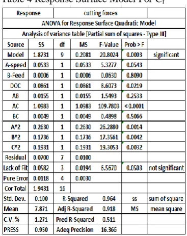
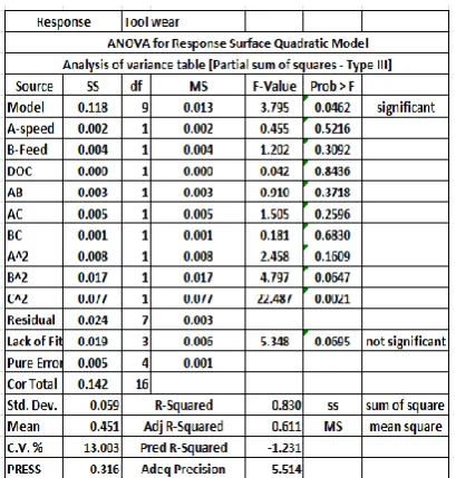
performed for discovering the significance of model, noteworthiness of individual factors, and determining the lack of fit. These are vital strides previously moving further to foresee the relationships. Analysis of variance (ANOVA)
is connected for condensing and recapitulates the tests performed in this study. ANOVA for RS- quadratic Model and the Partial sum of squares - Type III, there are different elements of ANOVA like sum of squares (SS), Degree of freedom (DF), Mean square value (MS), Model value (F), probability (P). For briefings and summing up the tests performed in this investigation is done with the application of ANOVA. The F-values of the Cf and Vbmax in the model are 20.80 and 3.80 respectively indicated the significance of the model for all. All variables are significant if the value of F is less than 0.05. In the current review, the prob.-value is 0.003 %, which means the model is significant. The "Lack of Fit F-values" of Cf and Vbmax are 6.57 and 5.35 which
implies for Cf, ‘lack of fit’ was not significant compared with
the pure error. The adequate precision in this experiment is 16.37 and 5.51 that implies adequate the signals to plan a model. Model is troubled if the probability is less than 10%. Hence, these values as talked about and showed that the produced display model is good. Transformation is required if the value of the model ratio is greater than 10 and if the value is less than 3, it means not significant transformation is required as shown in table 4&5. Table 6 provides the results for the Cf and
Vbmax from DOE.
[image:4.595.56.248.593.674.2]Table 4 Response Surface Model For Cf
Table 6 Experiment Results For The Cf And Vbmax From
DOE
4.2 Modelling Of Cutting Forces And Tool Wear
In the current Study, parametric representation of cutting forces and tool wear have been formulated and tried to develop an association with machined parameters as shown in the equation no. 5&6.
Cutting forces = +17.99 -0.82 *(.A) + 0.0088 *(.B) + 0.1 * C + 0.062 * (.A)*(B) – 0.52 * (A) *(C)- 0.035 * (.B) * (C)-
0.25 * (A)2 + 0.20 * (B)2 – 0.21 *( C)2 (5)
Flank-wear = +0.38-0.014*(A) + 0.023*(B) - 0.0043*(C) - 0.028*(A)*(B) + 0.036*(A)*(C) + 0.013*(B)*(C)
-0.045*(A)2 + 0.063*(B)2 + 0.14*(C)2 (6)
From equation no. 5 & 6, the different parameter’s like A: speed., B: Feed., C: DOC are shown in coded form. The model is proposed to show the analysis of the predicted values of the machined forces and Vbmax. on another process variables. By utilizing the mathematical model, the forecasts of the machined forces and flank wear on the operational surfaces of AlSiMMC could be made.
VI. ANALYSIS OF RESULTS
The various results of Cf and Vbmax behaviour and their
mathematical model, statistical analysis, cube-plot and Overlay Plot are explored in the next coming session as follows. The results explored that the tool flank wear and tangential cutting force increase with an increase in the depth of cut and feed rate, however, tangential force decreases with an increase in the cutting speed. This could be due to the effect of chatter or vibration which usually occurred at these cutting conditions during milling of AlMMCs. Reasons behind the increase in the tool wear and tangential forces are due to the huge amount of friction develops at the interference which causes BUE at high speed, feed and depth of cut. The optimum value for the Cf was 17.748 N at the
[image:5.595.56.238.305.465.2]range of speed: 3800- 4000 rpm, Feed: 220- 350 mm/min. and DOC: 1.75 to 2.00 mm as depicted in the fig.3. The lowest Vbmax was 0.35 mm at the same range of speed, feed but the varying DOC having a max limit of DOC was at 1.75 mm as appeared in the fig.4
[image:5.595.317.518.320.499.2]Fig. 3 Response Plot For Cf.
Fig. 4 Response Plot For Vbmax
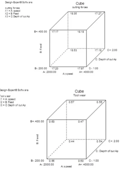
The various values of Cf and
Vbmax are depicted in the cube
Vb (max) is 0.44 and force is 17.17 N and other values of
force and Vb (max) at various process parameters are as
depicted in the figure no.5.The variation in Cf and Vbmax
are due to different loads acting on the tool, (i) mechanical load by the SiC hard particle cause adhesive wear and (ii) thermal load due to low speed meets the melting point of the AlMMCs which generated local high-temperature region and hence the failure of the tool. The optimum value of the Cf
[image:6.595.52.254.196.480.2]and Vbmax. according to the DOE is at 17.2 N and 0.5 mm respectively at cutting speed:2000, Feed:219.2 and DOC: 1.06 as shown in table 7.
[image:6.595.314.521.217.385.2]Fig. 5 Cube Plot For The Cf And Vbmax.
Table 7 Solutions For The Cf And Vbmax From DOE
VII. MODELING AND OPTIMIZATION A noteworthy undertaking of any exploratory examination in the field of machining is to accomplish the coveted yield of the ideal variables at least costs in order to extend the general productivity of the concerned procedure.
6.1 Statistical Analysis
Response.surface.methodology (RSM) is a decent approach to determine the optimum combination of input/output parameters in any activity for the optimization with the most noteworthy attractive desirability. In this experimental study, it has been explored to optimize the various machined parameters with an objective to reduce the Cf and Vbmax. In order to optimize the process parameters
having objective to enhance the productivity are shown in the perturbation plot and ramp function graph as depicted in Fig.6, &7.
Fig. 7 Ramp Function For The Cf And Vbmax For An
Optimized Combination
6.2 Optimization Of Cutting Forces And Tool Wear UsingPSO
This examination has displayed the optimization of the milling by utilizing Pso. An RSM model was implemented to anticipate the Cf and Vbmax during the machining and the
Pso technique was utilized to acquire the ideal speed and feed rate. This paper opens the entryway for another class of evolutionary optimization methods in the region of machining. This paper likewise displays the essentials of Pso optimization methods. While a number of evolutionary optimization methods have been produced for combinatorial improvement issues, the Pso has been fundamentally created for consistent optimization issues. The Pso can be a proficient streamlining device for tackling nonlinear persistent optimization issues, combinatorial improvement issues, and blended with non-linear optimization issue. In the present work, take after the standard procedure with respect to the usage of PSO. The model equations were utilized as a fitness function model show in the MATLAB programming. The ideal parameters were computed taking reaction with reducing of the Cf and Vbmax. Table 5
demonstrates the ideal outcomes gotten by Pso technique with a target of reducing the value of Cf and Vbmax With a
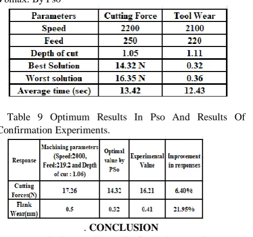
specific end goal to affirm the productivity regarding rate achievement and the normal time of Pso calculation, hundred in number test were performed and it has been watched that the normal achievement rate
[image:6.595.58.261.570.700.2]having the normal time of 13.42 s and 12.43 s for Cf and
Vbmax by Pso programed. This is because of the way that, the
search domain is guided by p &g-best values. Likewise, from Table 8, discovered that the ideal estimation of the Cf and
Vbmax acquired through PSO is nearer to the trial value.
Moreover, in view of these ideal outcomes, it can be guaranteed that the estimation of the Cf and Vbmax is
diminished to 6.4 % and 21.95 % through optimization as depicted in table 9.
Table 8 The Optimum Cutting Condition For Cf And
Vbmax. By Pso
Table 9 Optimum Results In Pso And Results Of Confirmation Experiments.
. CONCLUSION
We tentatively experimentally focused on cutting power and tool life variation in the milling of AL6061/Sicp with uncoated WC under unlubricated condition, lastly broke down the relationship between's the forces and flank wear. Investigation of fluctuation of the outcomes was made to legitimize the model fitness and to check the adequacy of the model. The accompanying perceptions are produced during the experimentation.
1. Dry milling of AL6061/Sicp, the force segment in the one-direction is more overwhelming of the other two segments and shows essentially higher extents than that of the values in other directions.
2. Flank wear and cutting forces are high while machining with higher DOC.
3. Flank wear is high at low speed because of developing high cutting forces due to the formation of BUE.
4. The result depicted in Pso is more accurate, claimed that the value of cutting forces and flank wear is reduced to 6.4 % and 21.95 % respectively.
The utilization of the fluid enhances the friction drag at tool rake face and the chips of the material. As an outcome, the tool wear and the cutting powers are by and large diminished. Further, nano fluid was applied to the machining of the AL-alloys and it was observed the positive effects in terms of reducing cutting power, cutting temperature, surface roughness and evacuating the chip etc. But the application of Nanofluid applies on machining of the AlMMC is not seen yet. Minimum quantity lubrication (MQL) with different lubricants may provide the better
results in term of cutting forces and tool behaviour as compared with the dry conditions.
REFERENCES
1. R. Ramanujam, K. Venkatesan, N. Kothawade, and J. Shivangkumar,
“Fabrication of Al-TiB 2 Metal Matrix Composites for Evaluation of Surface Characterization and Machinability,” January, 2015 vol. 8, pp. no. (85–89).
2. E. Zalnezhad, A. A. D. Sarhan, and M. Hamdi, “Optimizing the PVD
TiN thin film coating’s parameters on aerospace AL7075-T6 alloy for higher coating hardness and adhesion with better tribological properties of the coating surface,” Int. J. Adv. Manuf. Technol., 2013 vol. 64, no. 1–4, pp. (281–290),.
3. M. Ravi Shankar, S. Chandrasekar, W. D. Compton, and A. H. King,
“Characteristics of aluminum 6061-T6 deformed to large plastic strains by machining,” Mater. Sci. Eng. A, 2005,vol. 410–411, pp. (364–368),.
4. S. Gopalakannan and T. Senthilvelan, “Application of response surface
method on machining of Al-SiC nano-composites,” Meas. J. Int. Meas. Confed., 2013, vol. 46, no. 8, pp. (2705–2715).
5. S. Durante, G. Rutelli, and F. Rabezzana, “Aluminum-based MMC
machining with diamond-coated cutting tools,” Surf. Coatings Technol., 1997, vol. 94–95, pp. (632–640).
6. I. Zaghbani and V. Songmene, “A force-temperature model including a
constitutive law for Dry High Speed Milling of aluminium alloys,” J. Mater. Process. Technol., 2009, vol. 209, no. 5, pp. (2532–2544). 7. P. Liu, J. Xu, and Y. Fu, “Cutting force and its frequency spectrum
characteristics in high speed milling of titanium alloy with a polycrystalline diamond tool,” J. Zhejiang Univ. Sci. A, 2011, vol. 12, no. 1, pp. (56–62).
8. C. K. Toh, “A study of the effects of cutter path strategies and orientations in milling,” J. Mater. Process. Technol., 2004, vol. 152, no. 3, pp. (346–356).
9. A. Manna and B. Bhattacharayya, “A study on machinability of
Al/SiC-MMC,” J. Mater. Process. Technol., 2003, vol. 140, no. 1–3 SPEC., pp. (711–716).
10. Y. K. Chou and J. Liu, “CVD diamond tool performance in metal matrix
composite machining,” Surf. Coatings Technol., 2005, vol. 200, no. 5–6, pp. (1872–1878).
11. T. Wang, L. Xie, and X. Wang, “Simulation study on defect formation
mechanism of the machined surface in milling of high volume fraction SiCp/Al composite,” Int. J. Adv. Manuf. Technol., 2015, vol. 79, no. 5–8, pp. (1185–1194).
12. J. P. Davim, “Design of optimisation of cutting parameters for turning
metal matrix composites based on the orthogonal arrays,” J. Mater. Process. Technol., 2003, vol. 132, no. 1–3, pp. (340–344).
13. I. Mukherjee and P. K. Ray, “A review of optimization techniques in
metal cutting processes,” Comput. Ind. Eng., 2006, vol. 50, no. 1–2, pp. (15–34).
14. A. Aggarwal and H. Singh, “Optimization of machining techniques — A
retrospective and literature review,” Sadhana, 2005, vol. 30, no. 6, pp. (699–711).
15. Y. C. Shin and Y. S. Joo, “Optimization of machining conditions with
practical constraints,” Int. J. Prod. Res., 1992, vol. 30, no. 12, pp. (2907–2919).
16. R. Gupta, J. L. Batra, and G. K. Lal, “Determination of optimal
subdivision of depth of cut in multipass turning with constraints,” Int. J. Prod. Res., 1995, vol. 33, no. 9, pp. (2555–2565).
17. Z. Michalewicz and M. Schoenauer, “Evolutionary Algorithms for
Constrained Parameter Optimization Problems,” Evol. Comput., 1996, vol. 4, no. 1, pp. (1–32).
18. Z. Khan, B. Prasad, and T. Singh, “Machining condition optimization by
genetic algorithms and simulated annealing,” Comput. Oper. Res., 1997, vol. 24, no. 7, pp. (647–657)
AUTHORS PROFILE
Ankush Kohli Research Scholar Mechanical Engineering, IKGPTU, Jalandhar, India.
H. S. Bains Dept. of Mechanical Engineering, PUSSGIRI, Hoshiarpur, India.
[image:7.595.50.298.185.417.2]