Abstract: Robotics and Neural Networks will play a major role in the future of manufacturing and automation process. Nowadays not many robotic systems are smart systems, in the sense that they operate on a predefined algorithm to do their task. This research focuses on a design and development of a robotic arm with a visual input. The robotic arm will perform its job with the help of visual aid. The system will analyze the input image upon which the decision to write a number using Stochastic Gradient Decent (SGD) algorithm. In a nutshell this research work shows how the neural network can be incorporated with robot arm control, which is a desired field of interest in development of smart robotic systems. This work presents where the robotic arm is incorporated together with a neural network to perform a task of writing numbers using vision.
Index Terms: Automation, Neural network, Robot arm, SGD, thermal vision,
I. INTRODUCTION
Since the age of industrial revolution when manufacturing process have shifted from hand production techniques to machines, people have been looking into ways of making such a process simpler and faster, especially when it comes to performing of repetitive tasks were precision and accuracy plays the major role. Robots are not only used to make the manufacturing process easier but also they are required to perform certain tasks that can be very dangerous to humans. Besides robots can work non-stop and thus this feature is very useful at production lines were large volume of products must be manufactured in a limited time. However, robot systems became very sophiscated in past few decades; they still cannot do every single type of tasks that humans can perform. Writing and recognition of text of one example of such a task, and which is very simple to almost every human.
From a person’s perspective writing is a task that requires recognizing a pattern, like a character or simple drawing and then reproducing it on a paper, whiteboard and etc. People perform such a process without giving a major thought and thus is doesn’t seem to be complex at all. This happens
Revised Manuscript Received on August 05, 2019.
P.Velrajkumar, EEE Department, CMR Institute of Technology, Bengaluru, India, Email: [email protected]
C.Senthilpari, Faculty of Engineering, Multimedia University, Cyberjaya, Malaysia.
P.Ramesh, EEE Department, CMR Institute of Technology, Bengaluru, India.
G.Ramanamurthy, Faculty of Engineering and Technology, Multimedia University, Melaka, Malaysia.
D.Kodandapani, EEE Department, CMR Institute of Technology, Bengaluru, India.
because human brain is very good at performing simple patterns recognition and its reproduction. But in order for a robot to achieve the same thing is not an easy task. All the processes that human brain performs are required to be explicitly stated and programmed into the robot system. In order for it to write something, it must have a structure that resembles the arm along with a gripper, which can hold a writing tool like pen, pencil, marker etc. But this is only half of the job since a vision based system with appropriate program must be implemented, which will see the character and do the recognition process. Once the desirable mechanical design is accomplished, the vision system must be developed with a pattern recognition algorithm which a challenging problem, due the very large variety of handwriting styles that varies from person to person. But once all of that is completed, the robotic arm will be able to write a number upon recognizing it.
This work includes the construction of robot arm structure, electronics design and implementation, software development for digit recognition. The robotic arm is equipped with thermal camera to perform the given task, light weight and cost-effective. Arduino board is used to control the robotic arm. Based on Optical Character Recognition (OCR) techniques, pattern recognition algorithm was developed that would distinguish numbers of various styles.
II. REVIEW OF ROBOTIC ARM
Designing process of a robotic arm is to determine the workspace to be allocated which will be set to user desired requirements. Once the workspace size is set, a decision must be made to choose an actuator driving system, which is needed for every axis the robot has. A necessary requirement is the drive system which is responsible for driving the necessary power in movement operations such as lifting and rotation. The dimensions of the robot arm may vary for different designs, but then it should be pointed out that in dimension are chosen with respect to the actuator size and characteristics such as torque and power. Strictly speaking, if any dimension changes are made to any part of the robot structure, this will require overhaul of all robot limbs to bring about balance and stability [1].
Various materials are available for the purpose of construction the robotic arm. But the decision of which material to use, may be not an easy task sometimes. Another factor is that certain
materials require specialized equipment to work with. So
Development of Smart Number Writing Robotic
Arm using Stochastic Gradient Decent
Algorithm
if such materials are picked, then the necessary tools should be acquired as well and sometimes that’s not possible if the objective is to keep it at low-cost [2]. A high modulus of versatility and elasticity can be found in metals without much of a stretch distort. Contrary to metals, polymers present opposite result where their modulus versatility and elasticity is low while maintain certain strength. According to Urmila Mesharan et.al., [3] FPGA system is flexible because it can be easily reconfigured by the end user and can deliver the performance that allows critical control functions to be implemented in hardware rather than software. Agus Bejo [4] implements a low-cost microcontroller to control a six DOF robot arm, have utilized MSP430F1611 which is a 16-bit RISC microcontroller developed by Texas instrument. Arduino based control unit for control of arm motion was implemented in [5 - 7]. Arduino unit is becoming a popular microcontroller these days for the construction of robotic arms.
Point-to-point (PTP) controlled robots can move starting with one indicated point then onto the next, however they are incapable of stopping at subjective points. Continuous path (CP) control empowers the robot to move the tool center point along determined path, such as lines and circles. In sensor control all objective and non-objective positions are computed before any movement begins in both PTP and CP control [8] – [11]. OCR applications have consistently brought up handwritten digit recognition and continue to do so with pattern classification research. It is not an easy task, due to the different handwriting styles numerous approaches have been proposed for extracting features, classifications and even post processing methods. To evaluate performance, many image databases are utilized as an entry dataset. Many recognition systems have been proposed in recent years, where the main aspect lays on higher recognition accuracy [12] – [14]. Over the past decade a ground breaking results by convolution neural network been shown in pattern recognition. Comparing to the classical ANN, number of parameters are greatly reducing when using the CNN. This achievement has allowed solving complex tasks by approaching larger models [15] - [17].
III. MATERIALS AND METHODS
The block diagram of the smart robotic arm using thermal vision is shown in Fig.1. The articulated configuration of robotic arm to be calculated. The major role in the design of robotic arm is torque. Torque can be described as a rotational force and is calculated using (1).
T = F * L (1)
The object’s weight is basically the force of gravity acting upon the object and is calculated using (2).
W = m * g (2)
This work was accomplished by using Meccano which is a model construction system. It consists of reusable metal and plastic parts, which are connected together by using nuts and bolts. Thus it enables the building of working models and prototypes much easier. The metal parts are made out of zinc alloy, which provides better corrosion resistance, stability,
[image:2.595.316.540.172.280.2]dimensional strength and impact strength. Motors work as actuators that are used in performing the movement of the robot arm links. Servomotors are used to control the movement of the arm. The advantage of servomotor is that once the control signal is sent, it will maintain the position of the arm. Servo implements an error feedback control through sensing which is utilized in order to correct the position angle of the motor shaft. Servo motor operates on DC voltage that allows manipulation of angular position with precision.
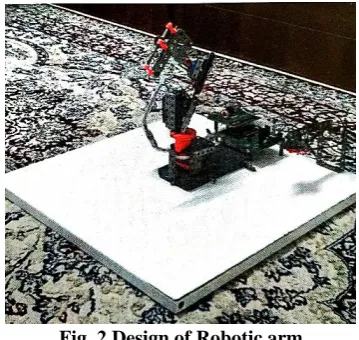
Fig. 1 Block Diagram of smart robotic arm The dimensions of the robotic arm were chosen according to the literature review that was carried out and the objective of the research, which requires the arm to write numbers as shown in Fig. 2. During the designing process of robotic arm, a few parameters were taken into consideration. Firstly, the distance between two consecutive motors needs to be minimum. This is due to the fact that links require a certain distance in order to maneuver. If the minimum distance is not granted, the link will collide into the motor which will result into restriction of its movement. Secondly, the shorter the link length is, the more weight motor would be able to handle. Finally, the design should be as light as possible, in order for the arm. The wrist of the arm is basically a pen holder mechanism. The way it is constructed is by attaching three steering arms to a perforated strip, through which the ball point pivot of 0.5 ballpoint pen is inserted. As well a spring from the same ballpoint pen was used, to give certain suspension for the ballpoint pivot. Hence the robot arm can perform writing on uneven surfaces.
[image:2.595.341.521.536.706.2]One of the objectives of this work requires the robotic arm to perform its writing operation based on its vision. For this purpose, a thermal camera is required that will act as the input device and that will capture the image of the handwritten digit. Even in dark environment the thermal camera can able to capture the image properly. The circuit board is designed to control four servo motors, perform serial communication and provides two additional digital inputs for the push buttons one of which upon being pressed displays the servo motor position if the robot arm is in the manual control mode and second exit the manual mode as shown in Fig. 3.
Fig. 3 Circuit Board Blocks
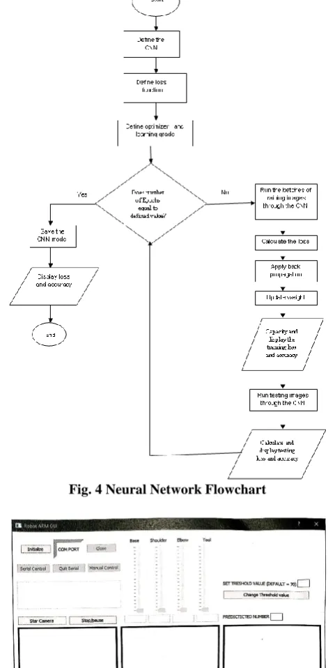
In order to examine the Neural Network (NN), MNIST database was utilized to train the NN, since it is a standard and large database of handwritten digits. Fig. 4 shows the flowchart of CNN model training process. The first step is to define the CNN architecture and that simply means to create the model class. Secondly, the loss is defined and this function will calculate the difference between predicted output digits with the actual label of the image. At the third step, definition of optimization algorithms and learning grade happens. Major role of optimizer in network’s training process is to minimize the loss during the training process. The optimizer that was chosen for CNN is Stochastic Gradient Decent (SGD) algorithm.
The Graphical User Interface (GUI) code has been written using PtCharm software, which is IDE that is developed for Python language. As well the layout design of GUI shown in Fig. 5 has been created in software Qt Designer that utilizes PyQt5 widget toolkit for creating embedded GUI’s. Upon the start of the GUI, its layout will be displayed on the smart device screen and the previously trained CNN model will be loaded. In the beginning the initialize button must be pressed in order to establish serial communication with arduino microcontroller, otherwise other functions will not be available. Except the start camera button and related functions to it, like capture image and predict, as it does not require serial communication. After the initialization of serial communication, the user has two options to control the robot arm. The servomotors angles are changed by dragging the different track bars. As well in order for robot arm to write numbers based on the predicted digit, serial control must be chosen as the GUI program will send the predefined algorithm for corresponding digit to the microcontroller.
[image:3.595.62.285.199.305.2]Fig. 4 Neural Network Flowchart
Fig. 5 Graphical user Interface IV. RESULTS AND ANALYSIS
During the development process of the NN, couple optimization algorithms were tested in order to identify which one of them yields better accuracy and lesser loss. Those algorithms are Stochastic Gradient Decent (SGD) and Adaptive Moment Estimation (Adam). At the beginning, the training process of the CNN was done few times with the parameter of twenty to thirty epochs for both optimizers. But that was not enough to determine which algorithm is better as the accuracy varied after each training procedure. Hence the epoch parameter was set to
[image:3.595.317.547.413.601.2]accuracy and loss of SGD and Adam optimizers can be seen in Fig.6(a) – (d).
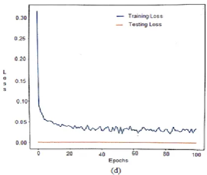
Fig. 6 (a) SGD Accuracy, (b) SGD Loss, (c) Adam Accuracy, (d) Adam Loss
From the fig. 6 (a) – (d), the testing loss for both cases is practically the same, except the fact that Adam maintained this statistic from start to the end while SGD had slightly higher in the beginning. Although training loss for both optimizers is lesser that 0.05%. The SGD has shown much smoother training loss curve over hundred iterations. SGD achieved 99% accuracy after 19 epochs and maintained it until the end of the training process. Adam performed the same, but after 22 epochs. For the testing accuracy, Adam has showed better results from the beginning of training process, starting from 98%, while SGD from 97%. But at the same time, both of them were able to achieve 99% accuracy. Except that SGD hit it after 40 epochs and maintained until the while Adam reached it only after few epochs but failed to maintain it through the whole training process. So SGD optimization algorithm was used in this research work.
The NN evaluation upon prediction of various numbers was trained. Upon start of the camera, the image for recognition should be placed properly. After the image is properly aligned, user must click Capture image button, thus the camera will take a snapshot of the image and display it in GUI. Next step is to click Predict button. That will process the image by converting it to binary and load it into the CNN model. Upon completion of this process the processed image along with the predicted value will be displayed in the GUI as shown in Fig. 7 (a).
[image:4.595.321.532.49.227.2]Fig 7 (b) CNN noisy image
This procedure was repeated for the rest of the digits from 1 to 9 and all of them have been successfully recognized. It should be noticed that the testing set was created, using clear and accurately written digits, so after this it was time to test how the CNN can handle not very clear and noisy images. The CNN was able to successfully recognize what was written as shown in Fig. 7 (b).
Fig 8 (a) NN model using default threshold value
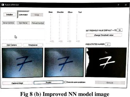
Fig 8 (b) Improved NN model image
Sometimes the image quality can be affected by the outer light conditions and in order to solve that problem, setting the different threshold value was introduced. In Fig 8 (a) the default threshold value was used, which is 70 and it can be seen that the NN model failed to recognize the digit 7 due to poor quality of the processed image. After the threshold value was increased to 90 as shown in Fig. 8 (b), the processed image quality became better and thus the CNN has successfully recognized digit 7. The robotic arm capture the CNN modeled image and successfully written on the paper or
corresponding surface.
V. CONCLUSION
In this work, a vision based robotic arm that writes digits upon recognition process of handwritten numbers has been presented. The 4 DOF robotic arm with a mechanism to hold the writing tool such as pen, was designed and constructed, The thermal camera is used to capture the image with handwritten number whereas the recognition system was implemented to identify that number. This recognition system is a convolutional neural network model, which was trained by using the MNIST database, to recognize different features of numbers in order to identify them. High performing language as Python along with different software tools were used to develop the NN and GUI. The GUI was designed to achieve the maximum flexibility and user friendly. The GUI allows the user to control the robotic arm in two different modes; by sending values to the actuators and by controlling it manually with the help of manipulator arm. In the GUI, user is allowed to change the threshold value in order to change the quality of the processed image that is used in the neural network for recognition process.
REFERENCES
1. P.Velrajkumar, CV Aravind, S.Solai Manohar, A Darwin Jose Raju, “Development of Real-Time Tracking and Control Mobile Robot using Video Capturing Feature for Unmanned Applications”, IEEE International Conference on Communication Control and Computing Technologies, India, 2010, pp. 90 – 92.
2. P.Velrajkumar, G.Ramanamurthy, J.Emerson Raja, Md.Jakir Hossen, Lo Kok Jong, “Controlling and Tracking of Mobile Robot in Real-Time using Android Platform”, Journal of Engineering and Applied Sciences, 12 (4), 2017, pp. 929 – 932.G. O. Young, “Synthetic structure of industrial plastics (Book style with paper title and editor),” in
Plastics, 2nd ed. vol. 3, J. Peters, Ed. New York: McGraw-Hill, 1964, pp. 15–64.
3. Urmila Meshram, Pankaj Bande, P.A.Dwaramwar, R.R.Harkare, “Robot arm controller using FPGA”, IEEE International Multimedia, Signal Processing and Communication Technologies, India, 2009, pp. 8 – 11.
4. Agus Bejo, Wanchalerm Pora, Hiroaki Kuneida, “Development of 6-axis robotic arm controller implemented on a low-cost microcontroller”, IEEE 6th International conference on Electrical Engineering / Electronics, Computer, Telecommunications and Information Technology, Thailand, 2009, pp.328 – 331.
5. Ankur Bhargava, Anjani Kumar, “Arduino Controlled Robotic Arm”, IEEE International Conference on Electronics, Communication and Aerospace Technology, India, 2017, pp. 376 – 380.
6. Chien-Wei Chen, Rui-Ming Hong, Hung-Yu Wang, “Design of a Controlled Robotic Arm”, IEEE International Conference on Green Technology and Sustainable Development, Taiwan, 2016, pp. 22 - 23. 7. Pronadeep Bora, Vishwajit Nandi, “Low cost shadow function based
articulated robotic arm”, IEEE International Conference of Energy, Power and Environment: Towards Sustainable Growth, India, 2015, pp. 1 - 4.
8. Anupama Kaushik, Himanshu Gupta, Digvijay Singh Latwal, “Impact of feature selection and engineering in the classification handwritten text”, IEEE International Conference Computing for Sustainable Global Development, India, 2016, pp. 2598 – 2601.
[image:5.595.63.282.50.220.2] [image:5.595.62.287.310.460.2] [image:5.595.62.286.486.654.2]oto
10.1109/ICCIDS.2017.8272641.
10. Mahmoud M.Abu Gosh, Ashraf Y.A.Maghari, “A Comparative study on handwriting Digit Recognition using Neural Networks”, IEEE International Conference on Promising Electronic Technologies, Palestine, 2017, pp. 77 – 81.
11. Matthew Y.W. Teow, “Understanding Convolutional Neural Networks using minimal model for handwritten digit recognition” IEEE International conference on Automatic control and Intelligent Systems, Malaysia, 2017, pp. 167 – 172.
12. Shyla Afroge, Boshir Ahmed, Firoz Mahmud, “Optical Character Recognition using back propagation neural network”, IEEE International Conference on Electrical, Computer and Telecommunication Engineering, Bangladesh, 2016, pp. 1 - 4. 13. Tianmei Guo, Jiwen Dong, Henjian Li, Yunxing Gao, “Simple
Convolutional Neural Network on image classification”, IEEE International Conference on Big Data Analysis, China, 2017, pp. 721 – 724.
14. Yan Yin, JunMin Wu, HuanXin Zheng, “Ncfm: Accurate handwritten digits recognition using Convolutional Neural Networks”, IEEE International Joint Conference on Neural Networks, Canada, 2016, pp. 525 – 531.
15. Mohamed Iqbal.M, Subatra.B, Kokila.M, Anjali M Nair, Jeshna Parveen.M, “Validation of Digital Simulation using Artificial Neural Network”, International Journal of Industrial Electronics and Electrical Engineering, 3(8), 2015, pp.113-116.
16. P.Ramesh, Dr.C.Sharmeela, “Nine Level MLI fed Single phase Induction Motor Drive with Compressor Load using Artificial Neural Network”, Journal of Electrical Engineering, 17,(2), 2017, pp.247-254. 17. Saad Albawi, Tareq Abed Mohammed, Saad Al-Zawi, “Understanding of a Convolutional Neural Networks” IEEE Internatioal Conference on Engineering and Technology, Turkey, 2017, pp. 1 - 6.
AUTHORS PROFILE
P.Velrajkumar obtained his B.E in Electrical and Electronics Engineering in 1997 from Noorul Islam College of Engineering, India. He obtained his M.E degree in Applied Electronics in 1999 from Hindustan College of Engineering, India. He has over 19 years of teaching / research experience. Currently he is working as an Associate Professor and Head of Center of Excellence in the Department of Electrical and Electronics Engineering, CMR Institute Technology, Bengaluru, Karnataka, India. His areas of interests are Control systems, Robotics and Automation. He served as Reviewer in International Journals and committee member in various international conferences. His professional memberships are Senior Member IEEE and Member IET.
Dr.C.Senthilpari had a post-graduated in M.Sc (Applied Electronics) and M.E (Material Science) at National Institute of Technology, Tiruchirappalli. He was joined as a lecturer in Multimedia University, (Malaysia) in 2005 and he obtained Ph.D. Degree from Multimedia University in 2009. His work is on VLSI Design and simulation analysis of new hardware circuits. He served as a committee member in various international conferences. He immersed himself in conducting research in chosen area of specialization, guiding Ph.D. projects and Master students and teaching at undergraduate and post graduate level. He is a Senior Member in IEEE (USA) and Member in IET (U.K). He also obtained Charted Engineer from IET (U.K).
Dr.P.Ramesh obtained his UG degree in Electrical Engineering from the Institution of Engineers (India), PG degree in Applied Electronics from Dr.MGR University, Chennai and PhD from Anna University, Chennai, in the year 2018. He is presently working as Associate Professor and Head-Department Research Committee in CMR Institute of Technology, Bengaluru, India. He has 18 years of experience in teaching. His research topics include Power electronic applications in Renewable Energy Systems.
Dr.G.Ramanamurthy C.Eng, MIET, SMIEEE received B.Tech degree from Nagarjuna University, Andhra Pradesh, India in 1990, M.Tech degree from G.B.Pant University of Agriculture & Technology, Utter Pradesh, India in 1993, and PhD from Multimedia University, Malaysia. Currently he is working as Lecturer in Faculty
of Engineering & Technology, Multimedia University (Melaka Campus), Malaysia. His main research interests include Embedded Systems, VLSI, Nanotechnology, Memory optimization, low-power design, FPGA, Evolutionary Algorithms.