International Journal of Innovative Technology and Exploring Engineering (IJITEE) ISSN: 2278-3075, Volume-8 Issue-9S3, July 2019
Abstract: Power electronic technology made possible to evolve inverter fed electric drives. Permanent magnet synchronous motors (PMSM) are in much importance and are used often due to its performance characteristics. PMSM gives less noisy operation with faster and more efficient operation. PMSM needs a digital inverter for its operation. The paper analyzes nine-level inverter fed PMSM drive. Multi-carrier level-shifted technique is used to generate control pulses. Simulation work of the proposed concept is carried out and the results are presented using MATLAB/SIMULINK software.
Index Terms: PMSM, Multi-Level Inverter, LSCPWM, Speed control
I. INTRODUCTION
For many of the applications in agriculture and industries, use of motors to drive mechanical loads is been increased. Motor is used to reduce the human efforts when working with mechanical type of loads. Motor is a device which converts electrical energy to mechanical energy. Motors can be broadly classified as AC and DC motors. Use of commutator and brushes in DC motors pushes them back against other type of motors though they have good performance characteristics. Induction motors and synchronous motors are well known types of AC motors. Induction motor contains rotor coils and stator coils for its operation which eventually affects the power factor and increases the use of copper giving out losses with reduced efficiency of the system. Permanent magnet synchronous motor (PMSM) [1-4] is a synchronous motor uses only permanent magnets on its rotor and windings on its stator.
Stator windings of PMSM are distributed winding and the back EMF (BEMF) is sinusoidal in shape [7-10]. No coils will be wounded on rotor circuit. This makes usage of PMSM in many applications over other type of motors [5-7]. Current flow in each winding (when excited) produces a magnetic field vector, which sums with the fields from the other windings. By controlling currents in the stator windings, a magnetic field of arbitrary direction and magnitude is produced by the stator. Torque is then produced by the attraction or repulsion between this net stator field and the magnetic field of the rotor.
Conventional inverters give out square wave alternating output voltage consisting of high distortion. Alternating quantity with high distortion cannot be fed to any device and needs smoothing filters. Inverters are made up of capacitors and inductors which make the output current smooth as
Revised Manuscript Received on July 22, 2019.
R. Sasidhar, Research Scholar, Department of Electrical & Electronics Engineering, Sri Venkateswara University College of Engineering, Tirupati, AP, India.
Dr. A. Lakshmi Devi, Professor, Department of Electrical & Electronics Engineering, Sri Venkateswara University College of Engineering, Tirupati,
compared to switching square wave output we get with a conventional inverter. If the distortion quantity is high, filter size also increases. This phenomenon led to development of multi-level inverters [8-10].
9-Level Diode Clamped
MLI
Permanent Magnet Synchronous
Machine
[image:1.595.312.542.206.311.2]DC Voltage Source
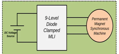
Figure 1: Representation of 9-level inverter fed PMSM Multi-level inverters became the prior pick for high power high voltage applications. Multi-level inverters are able to generate high voltage with lower rated devices. Multi-level inverter generates leveled (stepped) output and as the number of level increases better output voltage waveform is obtained. Diode clamped multi-level inverters are one among multi-level topologies and uses diodes as clamping elements. Multi-level inverter driven PMSM is shown in figure 1.
PMSM needs a digital inverter for its operation. The paper analyzes nine-level inverter fed PMSM drive. Multi-carrier level-shifted technique is used to generate control pulses. Simulation work of the proposed concept is carried out and the results are presented using MATLAB/SIMULINK software.
II. PROPOSEDNINE-LEVELDIODE-CLAMPED INVERTERFEDPMSMDRIVE
Multilevel inverters (MLI) are becoming increasingly popular in power applications, as multilevel inverters have the ability to meet the increasing demand of power rating and power quality associated with reduced harmonic distortion and lower electromagnetic interference. Multilevel inverters are capable of generating output voltage with very low harmonic distortion with low dv/dt. Diode clamped MLI (DCMLI) shown in figure 2 or also called as neutral point clamped MLI is one of the topology of multi-level structure. Diodes, capacitors plays important role in the operation of generating multi-level output from diode-clamped inverter. Diode-clamped inverter presents only half the amount of input voltage at the output.
Speed Control of PMSM Drive fed with Nine
Level Inverter
Figure 2: 9-level diode clamped inverter
[image:2.595.44.296.55.379.2]Figure 3: Output of 9-level DCMLI Table-1: Switching pattern for 9-level DCMLI
Volt A1 A2 A3 A4 A5 A6 A7 A8
V9 1 1 1 1 1 1 1 1
V8 0 1 1 1 1 1 1 1
V7 0 0 1 1 1 1 1 1
V6 0 0 0 1 1 1 1 1
V5 0 0 0 0 1 1 1 1
V4 0 0 0 0 0 1 1 1
V3 0 0 0 0 0 0 1 1
V2 0 0 0 0 0 0 0 1
V1 0 0 0 0 0 0 0 0
Volt A1* A2* A3* A4* A5* A6* A7* A8*
V9 0 0 0 0 0 0 0 0
V8 1 0 0 0 0 0 0 0
V7 1 1 0 0 0 0 0 0
V6 1 1 1 0 0 0 0 0
V5 1 1 1 1 0 0 0 0
V4 1 1 1 1 1 0 0 0
V3 1 1 1 1 1 1 0 0
V2 1 1 1 1 1 1 1 0
V1 1 1 1 1 1 1 1 1
VDC
PMSM
Ph-A
Ph-B
Ph-C
9-Level Diode Clamped Inverter
Figure 4: 9-level DCMLI fed PMSM
Figure 3 shows the output obtained from 9-level DCMLI and table-I shows switching pattern of 9-level DCMLI. Figure 4 shows the 9-level DCMLI fed PMSM.
III. CONTROLSTRATEGY
w
refw
act+
-I
d*
I
q=0
+
-I
abc*
I
(abc)actPWM Generator Gate
Pulses To DCMLI
from PMSM motor dqabc PI
PWM Reference
[image:2.595.306.543.320.473.2]Carrier Signal
[image:2.595.40.300.443.706.2]International Journal of Innovative Technology and Exploring Engineering (IJITEE) ISSN: 2278-3075, Volume-8 Issue-9S3, July 2019
VDC
PMSM
Ph-A
Ph-B
Ph-C
9-Level Diode Clamped Inverter
[image:3.595.310.543.51.398.2]Feedback to Controller
Figure 6: 9-level DCMLI fed PMSM with control IV. SIMULATIONRESULTS
[image:3.595.50.293.54.353.2]A. PMSM with fixed speed
Figure 7: Speed of PMSM drive
Speed of PMSM running with fixed speed condition is shown in figure 7. Reference speed signal and the actual speed (in blue) signal are shown in figure 7. The actual speed follows the reference speed 3000 RPM. Actual speed rises to final value and PMSM runs at constant 3000 RPM.
Figure 8: Torque of PMSM drive
Figure 8 shows the torque of PMSM. PMSM generates torque of 5 N-m corresponding to 3000 RPM. After initial transient in torque, the signal remains constant with 5N-m. As the speed is maintained constant, torque also remains constant.
[image:3.595.49.289.365.519.2]Figure 9: Three-Phase stator currents of PMSM
Figure 10: THD in stator current
[image:3.595.308.547.475.589.2]Figure 9 illustrates three-phase stator currents of PMSM. Three-phase PMSM stator coils draws 10A current. Magnitude in three phases of stator coils remains with constant peak. Harmonic distortion FFT window of stator current is shown in figure 10. Stator current is distorted by 0.26% and is well within nominal distortion limits.
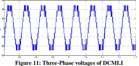
[image:3.595.50.290.580.721.2]Figure 12: THD in phase voltage of DCMLI Figure 11 illustrates three phase voltages of diode clamped inverter. Phase voltage is leveled with nine magnitudes yielding nine-level voltage signal. Peak magnitude of phase voltage in three phases is 250V. Harmonic analysis in phase voltage signal is shown in figure 12. FFT window displayed shows 18.71% distortion in phase voltage of DCMLI.
Figure 13: Three-Phase Line voltages of DCMLI
Figure 14: THD in line voltage of DCMLI
Figure 13 illustrates three-phase line voltages of diode clamped inverter. Peak magnitude of line voltage in three phases is 500V.. Harmonic analysis in line voltage signal is shown in figure 14. FFT window displayed shows 16.08% distortion in line voltage of DCMLI.
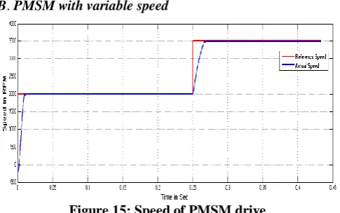
[image:4.595.307.550.121.273.2]B. PMSM with variable speed
Figure 15: Speed of PMSM drive
Speed of PMSM running with variable speed condition is shown in figure 15. Reference speed signal (green) and the actual speed (blue) signal are shown in figure 15. The actual speed follows the reference speed as shown in figure. Initial PMSM run speed reference value is set to 2000 RPM and PMSM follows the set speed and continues to run at 2000 RPM. At time 0.25 seconds, reference speed command is set to 3500 RPM. The closed-loop speed control sets PMSM to follow the reference speed command and hence after 0.25 seconds PMSM speed rises to 3500 RPM and follows reference speed.
Figure 16: Torque of PMSM drive
[image:4.595.50.290.373.763.2] [image:4.595.309.568.407.536.2]International Journal of Innovative Technology and Exploring Engineering (IJITEE) ISSN: 2278-3075, Volume-8 Issue-9S3, July 2019
Figure 17: Three-Phase stator currents of PMSM
Figure 18: THD in stator current
[image:5.595.51.291.53.763.2]Figure 19: Three-Phase voltages of DCMLI
Figure 20: THD in phase voltage of DCMLI Figure 19 illustrates three phase voltages of diode clamped inverter. Phase voltage is leveled with nine magnitudes
[image:5.595.306.558.177.600.2]yielding nine-level voltage signal. Peak magnitude of phase voltage in three phases is 250V. As speed change command is given at 0.25 seconds, the frequency of the phase voltages in DCMLI increases with the same peak magnitude. As the speed in synchronous machines varies with frequency with constant number of stator poles, PMSM phase voltage frequency increases proportionally after speed is increased from 2000RPM to 3500RPM at 0.25 seconds. Harmonic analysis in phase voltage signal is shown in figure 20. FFT window displayed shows 16.04% distortion in phase voltage of DCMLI.
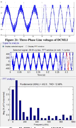
Figure 21: Three-Phase Line voltages of DCMLI
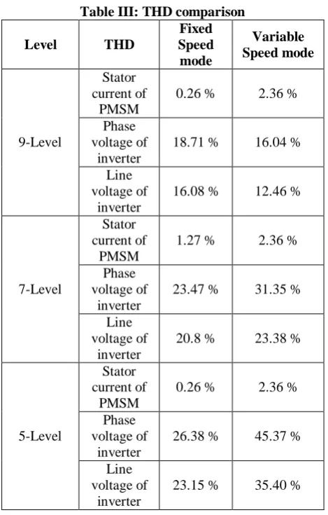
Figure 22: THD in line voltage of DCMLI Figure 21 illustrates three-phase line voltages of diode clamped inverter. Peak magnitude of line voltage in three phases is 500V. Phase-A is illustrated in red colour, phase-B in green and phase-C in blue colour. As speed change command is given at 0.25 seconds, the frequency of the line voltage of DCMLI increases with the same peak magnitude. As the speed in synchronous machines varies with frequency with constant number of stator poles, PMSM line voltage frequency proportionally increases after speed is increased from 2000RPM to 3500RPM at 0.25 seconds. Harmonic analysis in line voltage signal is shown in figure 22. FFT window displayed shows 12.46% distortion in line voltage of DCMLI. Table III illustrates
operation with different levels of DCMLI [12], [13]. Table III: THD comparison
Level THD
Fixed Speed mode Variable Speed mode 9-Level Stator current of PMSM
0.26 % 2.36 % Phase
voltage of inverter
18.71 % 16.04 %
Line voltage of
inverter
16.08 % 12.46 %
7-Level
Stator current of
PMSM
1.27 % 2.36 %
Phase voltage of
inverter
23.47 % 31.35 % Line
voltage of inverter
20.8 % 23.38 %
5-Level
Stator current of
PMSM
0.26 % 2.36 % Phase
voltage of inverter
26.38 % 45.37 %
Line voltage of
inverter
23.15 % 35.40 %
V. CONCLUSION
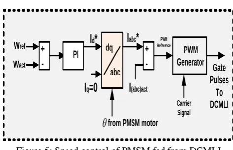
PMSM drives are becoming very good option for industrial and agricultural applications these days. The paper analyzes nine-level inverter fed PMSM drive with fixed and variable sped operations. Closed loop control with PI controllers is analyzed with fixed and variable speed conditions. With the simple closed-loop speed control technique, actual speed follows the reference speed with both fixed speed condition and also with variable speed condition which is validated with simulation results. DCMLI operation with switching sequence is explained. Pulses to DCMLI are generated from PWM generator using LSCPWM pattern. Reference signal obtained from speed control is compared with high frequency carrier signal to generate gate pulses to DCMLI switches. The control strategy is validated for fixed speed and variable speed condition.
REFERENCES
1. R. Krishnan, “Permanent Magnet Synchronous and Brushless DC Motor Drives,” CRC Press, Taylor and Francis Group. ISBN-978-0-8247-53849
2. Paul C.Krause, Oleg Wasynczuk, Scott D.Sundhoff, “Analysis of Electric Machinery and Drive Systems,” IEEE Press Power Engineering society ISBN-0-471-14326-X
3. H,Madadi Kojabad, G.Ahrabian, “Simulation and analysis of the interior permanent magnet synchronous motor as a brushless AC-drive,” Science direct / Simulation practice and theory 7(2000) 691-707
4. Pragasan Pillay, R.Krishnan.” Modeling of Permanent Magnet Motor Drives”, IEEE vol.35,no.4,november 1988
5. R. Dhaouadi, N. Mohan and L. Norum, "Design and implementation of an extended Kalman filter for the state estimation of a permanent magnet -50 l synchronous motor," IEEE Trans. Industrial Electronics, vol. 6, no. 3 0 0.1 0.2 0.3 0.4 0.5 0.6 0.7 0.8 0.9 1 Jul. 1991, pp.491 497.
6. K. Rajashekara, A. Kawamura and K. Matsuse, "Sensorless control of AC motor drives", New York: IEEE Press, 1996. 7. G. Sree Lakshmi, S. Kamakshaiah and T. R. Das, "Closed loop PI
control of PMSM for hybrid electric vehicle using three level diode clamped inverter for optimal efficiency," Energy Efficient Technologies for Sustainability (ICEETS), 2013 International
Conference on, Nagercoil, 2013, pp. 754-759.
8. L. Samaranayake, Y. K. Chin and U. S. K. Alahakoon, "Distributed control of permanent magnet synchronous motor drive systems," Power Electronics and Drive Systems, 2003. PEDS
2003. The Fifth International Conference on, 2003, pp. 710-715
Vol.1.
9. H. H. Lee and U. H. Jeong "A Study on Speed Synchronization for Multi Motors using Controller Area Network" IEEE Trans. Ind. Appl., vol. 44 no. 4 2000.
10. L. Feng Y. Koren and J. Borenstein "Cross-Coupling Motion Controller for Mobile Robots" IEEE Trans. on Control Systems Technology, vol. 1 December 1993.
11. R. Sasidhar, Dr. A. Lakshmi Devi, “Analysis of Five-Level Diode Clamped Multi-
12. Level Inverter Fed Permanent Magnet Synchronous Machine Drive” Jour of Adv Research in Dynamical & Control Systems, Vol. 10, 07-Special Issue, 2018, pp. (220-233)
13. R. Sasidhar, Dr. A. Lakshmi Devi, “Speed Control Analysis Of Lscpwm Driven Seven-Level Inverter Fed Permanent Magnet Synchronous Motor Drive”, ARPN Journal of Engineering and Applied Sciences, VOL. 14, NO. 1, JANUARY 2019, pp 299-306.
AUTHORSPROFILE
Mr. R. Sasidhar is a Full – Time research scholar pursuing his Ph. D in Department of EEE, Sri Venkateswara University, Tirupati since 2016. He received his M. Tech degree from JNTU-Hyderabad in 2010. He received his B. tech degree from JNT University, Kakinada in 2000.
Dr. A. Lakshmi Devi is a Professor in the
Department of Electrical and Electronics
Engineering, Sri Venkateswara University,