Three-Dimensional EXIT Chart Analysis of Iterative Detection Aided Coded Modulation Schemes
R. Y. S. Tee, S. X. Ng and
1L. Hanzo
School of ECS, University of Southampton, SO17 1BJ, UK.
Tel: +44-23-8059 3125, Fax: +44-23-8059 4508
Email:
1[email protected], http://www-mobile.ecs.soton.ac.uk
Abstract – The iterative convergence of iteratively detected coded modulation schemes having different block lengths, decod-ing complexity and an unequal error protection capability is stud-ied, when communicating over AWGN channels using 8PSK mod-ulation. More specifically, the coded modulation schemes investi-gated include Multilevel Coding (MLC), Trellis Coded Modula-tion (TCM), Turbo Trellis Coded ModulaModula-tion (TTCM), Bit-Inter-leaved Coded Modulation (BICM) as well as Bit-InterBit-Inter-leaved Coded Modulation employing Iterative Decoding (BICM-ID). A novel three dimensional EXIT chart was introduced for studying the it-erative convergence behaviour of the Multistage Decoding (MSD) scheme used in MLC.
1. INTRODUCTION
The philosophy of coded modulation was proposed by Imai [1] in his pioneering work on Multilevel Coding (MLC) and by Ungerb¨ock [2] in the context of Trellis Coded Modulation (TCM). MLC was orig-inally designed for protecting each of the modulated bits using dif-ferent component codes. It offers a flexible-rate code design philos-ophy and the attractive capability of providing unequal error protec-tion. Classic channel capacity rules based on mutual information have formed the basis of designing the component codes’ coding rates [3]. Multistage Decoding (MSD) has been widely used for the decoding of MLCs as the benefit of their reduced decoding complexity, while Parallel Independent Decoding (PID) has been proposed for the sake of reducing the associated decoding delay [4].
Trellis Coded Modulation (TCM) [2] was proposed based on the joint design of modulation and coding in order to maximize the Free Euclidean Distance (FED) when communicating over Additive White Gaussian Noise (AWGN) channels. TCM uses Ungerb¨ock’s Set Par-titioning (SP) principle as its mapping strategy, which imposes a low decoding complexity. Turbo Trellis Coded Modulation (TTCM) [5] employs the well-established structure of Turbo codes [6] using TCM as its component codes. With the parallel concatenated turbo encod-ing structure in mind, the upper TCM component encoder processes the original information bits, while the lower TCM component en-coder encodes an interleaved version of the upper one.
Zehavi further advanced the state-of-the-art by proposing Bit-Interleaved Coded Modulation (BICM) [7], where independent bit interleavers are used in conjunction with Gray Mapping for increas-ing the achievable time-diversity order and consequently to enhance the Effective Code LengthL, especially in a Rayleigh fading envi-ronment. However, this is achieved at the expense of a reduced mini-mum Euclidean distance, which inevitably results in a reduced perfor-mance for transmission over AWGN channels. Bit Interleaved Coded
The financial support of the EPSRC, UK and that of the European Union under the auspices of the Phoenix and Newcom projects is gratefully acknowl-edged.
Modulation assisted by Iterative Decoding (BICM-ID) [8] using a SP based mapping strategy was designed to improve the minimum Eu-clidean distance and to achieve an iteration gain in comparison to non-iterative BICM. The specific mapping of the bits to the symbols used in BICM-ID schemes determines much of the attainable performance gain and hence it has to be optimized.
In this paper, we comparatively study various coded modulation schemes. We invoke a novel 3D EXIT chart for characterizing the iterative MSD behaviour of MLC system compared to both BICM-ID and to TTCM schemes. The rest of the paper is organized as follows. In Section 2 we describe the system structure used. Our simulation results characterizing the different schemes are detailed in Section 3. In Section 4 we invoke EXIT charts in our convergence study, while our conclusions are presented in Section 5.
2. SYSTEM OVERVIEW
In our studied system, random information bitsuare generated as our source data before being fed into the encoders. The bitsvof the coded sequence are then appropriately interleaved and mapped to the 8PSK constellation points using the mapping function ofµ(v). The channel imposes the AWGNn, where the complex AWGN-valued noise variables are represented byn = nI +jnQ, which have a variance and double sided noise power spectral density obeyingσ2= σ2
I=σ2Q=N0/2.
At the receiver, the demapper converts the received signals to log-arithmetic domain probabilities. These probabilities are then deinter-leaved and fed into the appropriate bit or symbol-based log MAP de-coders [6]. The log-domain branch metrics of the symbol-based MAP decoders [6] are computed based on the Gaussian PDF of
p(yk|xk) = √1
2πσne
−|yk2−σxk2 |2
n . (1)
Both MSD [3] and PID [3] may be used for MLC decoding, where theN en(de)coders convey a total ofN modulated bits. In MSD eachextrinsicinformation value of protection leveli, fori ∈
{0,1, ..., N −1} is fed back to the demapper, before being used by the decoder of protection level (i+ 1). By contrast, in PID of MLC [3], allN decoders will carry out their decoding operation at the same time, before utilizing theextrinsicinformation in the next iteration. When encoding mnumber of data bits, the coding rate for TCM, BICM and BICM-ID becomesR = mm+1 for a2m+1 -ary modulated signal constellation. When the number of uncoded bits in TCM ism < m, we have 2m parallel transition branches in the trellis, which results in a reduced decoding complexity [2]. In the context of MLC, the coding rate of the amalgamated scheme would beR = R0+R1+...+RN−1, when assumingN levels of potentially different-rate encoding. The coding rate of each com-ponent code of the MLC scheme to approach the channel capacity
Mapping Type Mapping Indices to Corresponding Signal Points (cos2πi/M, sin2πi/M) for
i∈ 0 1 2 3 4 5 6 7
Gray 0 1 3 2 6 7 5 4
SP 0 1 2 3 4 5 6 7
BP 7 3 6 2 4 0 5 1
[image:2.595.52.283.56.134.2]MP 0 2 1 7 4 6 5 3
Table 1: Different bit to symbol Mapping Strategies : Gray, Set Par-titioning (SP), Block ParPar-titioning (BP) and Mixed ParPar-titioning (MP) [3], whereMis the number of constellation points.
may be determined with the aid of the capacity design rules of [3]. The chain rule of mutual information exchange in the context of our 8PSK schemes is formulated asI(Y;A) = I(Y;X0, X1, X2) = I(Y;X0) +I(Y;X1|X0) +I(Y;X2|X0, X1), whereAis the ran-dom input symbol,Xis the modulated symbol andY is the received channel-contaminated symbol. Convolutional codes are used as com-ponent codes in all of the TCM, TTCM, BICM, BICM-ID and MLC schemes. These convolutional codes are punctured, when requiring high coding rates. For the sake of achieving the best possible per-formance, a range of different bit to symbol mapping strategies are employed in our coded modulation schemes. Specifically, Gray Map-ping, Set Partitioning (SP), Block Partitioning (BP) and Mixed Par-titioning (MP) [3] are used, which map the natural coded bits to the different modulated constellation points, as shown in Table 1.
3. SIMULATION RESULTS
In this section we present simulation results for the previously men-tioned range of different coded modulation schemes. The effective throughput of the system is log2(M)R, when using anM-ary mod-ulation constellation and an overall coding rate ofR. The effective throughput is chosen ere as 2 Bits Per Symbol (BPS) with 8PSK mod-ulation. The component codes are punctured convolutional codes of coding rateR0 = 1/3, R1 = 3/4, R2= 11/12[4]. Due to the spe-cific coding rates that are readily available for convolutional codes, we do not follow the exact capacity rules proposed in [3] for adjusting the MLC scheme’s coding rate.
Coded modulation schemes exhibit an implementational complex-ity, which is exponentially proportional to both the number of trellis decoding states and the number of iterations. Since the number of trel-lis states is2K, whereKis the memory of the codes, both TCM and BICM have a complexity, which is proportional toν= 2K. TTCM invokes two TCM component codes andndecoding iterations, hence its complexity is proportional toν = 2.n.2K. BICM-ID feeds its
extrinsicinformation from the decoder to the demodulator during
each decoding iteration. The complexity of the demapper may be as-sumed to be insignificant. Hence BICM-ID exhibits a complexity, which is proportional toν=n.2M. By contrast, MLC hasi compo-nent codes with each of the compocompo-nent codes having a memory ofKi. Hence, its complexity atniterations, when using MSD is commen-surate with the sum of the individual decoder’s complexity, which is expressed asν=n.ii==0N−12Ki.
Figure 1 shows the beneficial effect of increasing the decoding complexity on the attainable BER performance of the various coded modulation schemes. All schemes have the same effective throughput of 2 BPS. Explicitly, 32-state MLC, 32-state BICM, 32-state TCM, 2x16-state TTCM and 32-state BICM-ID exhibit a similar complex-ity. Observe in Figure 1 that non-iterative TCM outperforms all the
1 2 3 4 5 6 7 8 9 10
Eb/N0(dB) 10-5
10-4 10-3 10-2 10-1 1
BER
1 2 3 4 5 6 7 8 9 10
Eb/N0(dB) 10-5
10-4 10-3 10-2 10-1 1
BER
BICM-ID, 32 states TTCM, 2x16 states TCM, 32 states BICM, 32 states MLC, 32 states BICM-ID, 32 states, 4 iterations TTCM, 2x16 states, 4 iterations TCM, 128 states
BICM, 128 states MLC, 32 states, 4 iterations
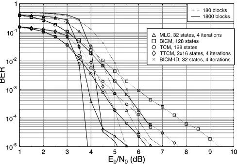
Figure 1: BER performance of 8PSK modulated MLC, TCM, TTCM, BICM and BICM-ID at a range of different complexities, for trans-mission over an AWGN channel using an interleaver block length of 1800 symbols.
other iterative schemes, which require several iterations to perform well. At BER =10−4TCM has an approximately 1dB coding advan-tage over both MLC as well as BICM, and a gain in excess of 3dB and 4dB, when compared to the corresponding TTCM and BICM-ID schemes, respectively. Without iterations, TTCM using punctured component codes does not benefit from sufficientextrinsic infor-mation exchange. Similarly, BICM-ID which was derived for fading channels using SP but no iteration has a poor Hamming distance. Still referring to Figure 1, we then increased the complexity of the various coded modulation schemes both by invoking a higher memory length and by increasing the number of iterations. Observe that TTCM out-performs the other coded modulation arrangements, closely followed by MLC and BICM-ID, which have quite similar performances, re-quiring anEb/N0 around 4.4dB for achieving a BER of10−4. In-creasing the memory length of TCM and BICM, the requiredEb/N0 becomes 5.3dB and 6.2dB, respectively. Hence, increasing the mem-ory length of TCM and BICM fromK=5 toK=7 and hence quadru-pling their complexity improves the performance by less than 0.5dB, while the iterative TTCM, MLC and BICM-ID schemes exhibit a sig-nificantEb/N0 improvement of up to 5dB upon quadrupling their complexity, which renders the latter iterative schemes more attractive. Figure 2 illustrates the effect of employing different interleaver block lengths by the various coded modulation schemes. More specif-ically, the block lengths of 180 and 1800 symbols are compared. In-creasing the interleaver block length improves the attainable perfor-mance, especially for the iterative schemes of MLC, BICM-ID and TTCM. Observe in Figure 2 that BICM-ID has a high sensitivity to the interleaver’s block length and at BER =10−4 it exhibits an approx-imately 1.5dB gain over the similar-complexity non-iterative BICM scheme having 128 trellis states. As seen in Figure 2, MLC shows a 1.35dB increase in coding gain at BER =10−4, as a benefit of using Nencoders, where each encoder requires a longer interleaver, when the input data is divided into a number of different-protection paral-lel streams. TCM and BICM obtain anEb/N0improvement of less than 1.5dB at BER =10−4and hence they are outperformed by the iterative schemes, especially by TTCM, as evidenced by Figure 2.
[image:2.595.307.551.60.229.2]1 2 3 4 5 6 7 8 9 10 Eb/N0(dB)
10-5 10-4 10-3 10-2 10-1 1
BER
1 2 3 4 5 6 7 8 9 10
Eb/N0(dB) 10-5
10-4 10-3 10-2 10-1 1
BER
1800 blocks 180 blocks
BICM-ID, 32 states, 4 iterations TTCM, 2x16 states, 4 iterations TCM, 128 states
[image:3.595.43.288.60.229.2]BICM, 128 states MLC, 32 states, 4 iterations
Figure 2: BER performance of 8PSK modulated MLC, TCM, TTCM, BICM and BICM-ID using different interleaver block lengths for transmission over AWGN channels at a given fixed complexity as-sociated with a total of 128 trellis states.
3.0 3.2 3.4 3.6 3.8 4.0 4.2 4.4 4.6 4.8 5.0 Eb/N0(dB)
10-5 10-4 10-3 10-2 10-1 1
BER
bit-2 bit-1 bit-0
TCM MLC MP, 2-iter MLC SP, 2-iter MLC BP, 2-iter
MLC-SP
[image:3.595.42.289.287.454.2]TCM
Figure 3: BER versusEb/N0 for the three different-integrity sub-channels in MLC using SP, BP, MP mapping, as well as TCM assisted by two turbo iterations.
an appropriate choice of encoded bits to modulated symbol constella-tion mapping. To elaborate a little further, all schemes in this figure have three input data bits that have to be protected. The individual decoded bits of both BICM-ID and TCM exhibit a similar BER per-formance, i.e. they have no UEP capability, as stated above. Similarly, the SP based mapping of MLCs does not provide the required UEP either, which is a consequence of the fact that the stronger code is ap-plied to the specific phasor constellation bits, which are separated by a small Euclidean distance, while the weaker codes at the higher pro-tection levels of the MLC scheme are supported by a large Euclidean distance. The MLC scheme using BP has an equal Euclidean distance for all of its three different bits. Note that bit 0 of the BP-based MLC scheme exhibits a BER below10−5 and thus its BER curve is not shown in the figure, while bit 2 has a clearly inadequate BER. The MP scheme has its bit 0 strongly protected, while both bit 1 and bit 2 exhibit a similarly inadequate BER performance.
4. EXIT CHART ANALYSIS
Extrinsic Information Transfer (EXIT) charts [9] constitute a useful tool in the design of iterative schemes, since the characteristics of the constituent components can be visualized based on their exchange of mutual information.
In our MLC schemes, the output of each convolutional compo-nent code is bit interleaved for the sake of providing an independent source of time diversity, since as a benefit of interleaving, the corre-sponding bit streams become fairly uncorrelated. The output LLRs of the decoders exhibit a Gaussian-like distribution [9]. Similarly, the inputa prioriinformationAof each component decoder is modeled by an independent Gaussian distribution. The mutual information of thea prioriLLRs of the decoder is given by [9]
IA(σA) = 1−
∞
−∞
e−((y−σ2A/2)2/σ2A)
√
2πσA
log2[1 +e−y]dy, (2)
whereσ2Ais the variance ofA. Given a sufficiently high number of received signal samplesNand thea prioriLLRsLnof a sequence ofnbits, the mutual information of the decoder’s extrinsic LLRs can be expressed as [10]
IE= 1−E{log2(1+e−L)} ≈1− 1 N
N
n=1
log2(1+e−xn.Ln), (3)
wherexnrepresents a sequence ofntransmitted bits, which constitute a subset of the total ofNsamples.
Decoder 1,D1
Decoder 2,D2 L(u0)
L(v0)
L2 e Lb2
L
b1 L1
e Lb1
L
b0 L
b2
Lb0
y
Decoder 0,D0
Demapp
er
L0 e
L(v1) L(u1)
L(u2)
[image:3.595.306.529.356.509.2]L(v2)
Figure 4: MSD decoder of the 8PSK modulated MLC scheme with channel informationy. The notationsL(ui)andL(vi)represent the output LLRs of the three decoders for both the information bits and the encoded bits. The subscriptirepresents the bit index inb0,b1 andb2. Furthermore, Lbi denotes the associated information bits’ LLRs for the corresponding decoderDi, which is further augmented in Figure 5, whileLbidenotes thea prioriLLRs forwarded by the otherdecodersDito the input of the inner demapper.Liedenotes the
extrinsicLLRs provided by the demapper.
-+ Ψ
+
-Ψ
Li
A Li
A(o)
Li
A(comb)
Ψ−1
y Pe(Vi
t)
Li
E LoA
Ψ−1 yˆ
Lo
E
Li
A(o)
Li
A(o)
Pa(Vi
t)
Lb0 Lb1 Lb2 Lb0 Lb1 Lb2 Lb0 Lb1 Lb2
Ii
E
Io
E
Li
A LiA
MAP Decoder Demapper
a prioriLLR for level 0, 1 and 2
[image:4.595.45.295.59.190.2]level0 level1 level2
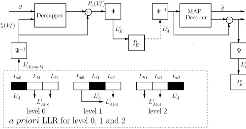
Figure 5: General structure of EXIT chart generation for the MSD of 3-level MLC when using 8PSK and three en(de)coders.Labrepresents the LLR values, where the superscriptadenotes the inner (i) or outer (o) codes, while the subscriptbdenotes the inputa priori(A) or out-putextrinsic(E) information. Lb0,Lb1 andLb2 are independent Gaussian distributed LLR generated for bits 0, 1 and 2 respectively. Furthermore,ΨandΨ−1denote the LLR-to-symbol probability and symbol probability-to-LLR conversion. The arrow drawn in dash line represents theextrinsicLLR demapper output, which becomes the LLR input of the decoder after demapping. The filled black box rep-resents thea prioriLLR of the associated information bit, while the hollow box denotes thea prioriLLR of the bits of theother de-coders. Finally,IEi andIEo denote the mutual information used for plotting the EXIT chart.
b1andb2, respectively. HenceLiA, which is the LLR associated with the black box in the figure, is generated fromLb0. Thea prioriLLRs generated by theotherdecoders areLb1andLb2, as indicated by the hollow boxes in Figure 5, are then computed along with their individ-ual average values for the sake of obtaining the combineda priori LLR ofLiA(o)as the input soft bit value for the iterative demapper. Similar operations are carried out at thelevel1and2decoders, each having the corresponding information bit represented by the black box at different position in Figure 5. The demapper of the MLC decoder is treated similarly to the demodulator of the iterative BICM-ID [11] scheme. When thea prioriprobabilityPais different from 0.5, the extrinsic probability of the MLC demapper is given by [11]
Pe(vit=b) =
vt∈χ(i,b)
P(yt|xt)
j=i
Pa(vtj=vj(xt))
. (4)
For 8PSK modulation, the bit index isi= 0,1,2, where we have vi = b,b ∈ {0,1}, and following the notation of [11], the subset
of modulated signals is denoted byχ(i, b) = {µ(v0, v1, v2)|vi = b;vj ∈ 0,1, j = i}. The mapping functionµ(.) of the different
mapping schemes, used in our design study was illustrated in Table 1. For an AWGN channel,P(yt|xt)is given by Equation 1. Since we havej=i, which excludes the own intrinsic information of each bit, the output LLR is only affected by theextrinsicinformation of the otherdecoders. Let us now investigate the decoding convergence of the schemes studied using a three-dimensional (3D) EXIT chart with reference to Figure 5 in the context of three different en(de)coders employing SP based labeling. To expound a little further, the reason for requiring a 3D EXIT chart in the context of our 8PSK based MLC scheme is, because when employing MSD there is an iterative infor-mation exchange amongst the three separate MLC decoders of the different protection levels, rather than between only two constituent decoders, as in the case of conventional EXIT charts. The results of our 3D EXIT chart analysis are shown in Figure 6. At each level of the
MLC decoding scheme, the demapper constitutes the inner decoder, while the outer decoders are the corresponding MAP decoders.
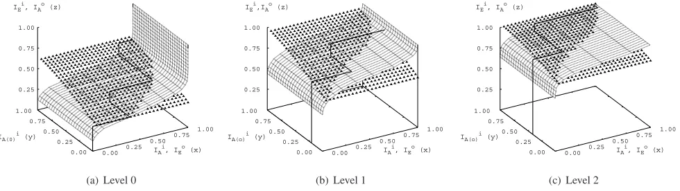
In Figure 6,IAi/IEi andIAo/IEo denote the mutual information of the inner and outer codes, respectively. Furthermore,IAi(o)in Figure 6 represents the mutual information at the demapper’s input gener-ated from thea prioriknowledge provided by theotherdecoders, where the superscriptirepresents theinnercode, while the subscript A(o)represents thea prioriknowledge gleaned from theother de-coders. As seen in Equation 4, theextrinsicprobability informa-tion exploited by the MLC demapper is only affected by the infor-mation bits provided by theotherdecoders, henceIEof the demap-per changes only as a function ofIAi(o), as seen in Figure 6. As ob-served in Figure 5, the mutual information is exchanged between the inner demapper by passingIEi to the outer MAP decoder, which it-eratively exchangesIEo with the inner demapper. In the 8PSK based MLC scheme, we have three different-integrity decoding levels (b0, b1, b2) and each level is represented in one of the three 3D EXIT charts shown in Figures 6(a), 6(b) and 6(c), respectively. In Figure 6, the EXIT plane marked with triangles is computed based on the in-ner demapper’s outputextrinsicinformationIEi at a givena priori inputIAi andIAi(o), characterizing itsextrinsicprobabilityPe for-warded to the outer MAP decoders. By contrast, the EXIT plane of Figure 6, which is represented by the mesh of rectangles was obtained based on the MAP decoder’sextrinsicoutputIEo at a given demap-per extrinsic informationIEi.
Commencing from decoder 0 having only the channel’s output information, but noa prioriLLR from theotherdecoders, theIEi trajectory curve emanates from the central corner of the graph in Figure 6(a), with thex, ycoordinate values equal to 0. When the extrinsicLLRLieprovided by the demapper output seen in Figure 4 is passed toD0, the decoding trajectory moves in a direction parallel to thexaxis at a certainIEo value, quantifying theextrinsic infor-mation contribution of the outer decoderD0. The outputextrinsic LLRL(v0)is then passed to the second-level demapper, where it be-comes thea prioriinformationLb0, as seen in Figure 4. Hence, at the second decoding level, the demapper benefits from both the chan-nel LLRs and thea prioriLLRsLb0 provided by the first decoded level. We can therefore observe thatIAi(o)of level 1 in Figure 6(b) emerges from a positive value of they axis. The iterative process evolves further then to the third decoder output at protection level 2, as shown in Figure 6(c). At the third decoderD2 of Figure 4, the extrinsicLLRsL(v2)are fed back as thea prioriinformationLb2 to the decoderD0of the first level. At this stage, namely during the second iteration, we can observe from Figure 6(a) that the trajectory ofIAi(o)moves in parallel to theyaxis as a benefit of thea priori knowledgeLb1 andLb2 provided by theotherdecoders from pro-tection level 1 and level 2 of the MLC scheme, and the output of the demapper 0 benefits from an iteration gain, where the decoding trajec-tory moves vertically along thezaxis, between the two EXIT planes denoted by the mesh of triangles and rectangles, respectively, reach-ing a specific value ofIEi. This is theextrinsicinformation gleaned during the second iteration in decoder 0. The same process contin-ues, as thea prioriinformation is forwarded from the first protection level towards the third protection level of the MLC scheme.
0.00 0.25
0.50 0.75 1.00 IA
i
, IE o
(x) 0.00
0.25 0.50 0.75 1.00
IA(0) i
(y) 0.25
0.50 0.75 1.00 IE
i
, IA o
(z)
(a) Level 0
0.00 0.25
0.50 0.75 1.00 IA
i
, IE o
(x) 0.00
0.25 0.50 0.75 1.00
IA(o) i
(y) 0.25
0.50 0.75 1.00 IE
i
,IA o
(z)
(b) Level 1
0.00 0.25
0.50 0.75 1.00 IA
i
, IE o
(x) 0.00
0.25 0.50 0.75 1.00
IA(o) i
(y) 0.25
0.50 0.75 1.00 IE
i
, IA o
(z)
[image:5.595.50.540.66.204.2](c) Level 2
Figure 6: 3D EXIT Chart for Level 0, Level 1 and Level 2 of the MLC scheme at SNR = 4dB.
as seen in Figure 6(b) and 6(c) respectively, approaching the pointQ (1,1,1) more closely. Hence, the iterative MLC scheme’s performance is limited. Furthermore, note that the decoding trajectory fits closely, but not exactly into the EXIT chart’s tunnel due to the fact that the MLC scheme’s three encoded bits become slightly dependent on each other after the first iteration and therefore the corresponding LLRs do not obey a perfect Gaussian distribution. Nonetheless, the 3D EXIT chart provides an adequate prediction of the MLC scheme’s iterative behaviour.
For the sake of comparison, Figure 7 shows the conventional two-dimensional EXIT chart of the BICM-ID and TTCM schemes studied in Figures 1 and 2. As observed, the EXIT chart tunnel of the BICM-ID scheme is relatively narrow and converges slowly to theP (1,1) point, requiringI=5 iterations to acquire its maximum iteration gain. By contrast, in the case of TTCM the tunnel is wider and steeper. When usingI=3 iterations, the system approaches its best possible performance, even though it starts at a lower initialIAvalue. We note furthermore that a narrow EXIT chart tunnel is indicative of operating close to channel capacity, possibly beyond the channel’s cut-off rate, where further performance improvements are only achieveable at the cost of a high interleaver delay and high complexity, associated with a high number of iterations.
0.0 0.1 0.2 0.3 0.4 0.5 0.6 0.7 0.8 0.9 1.0
IE outer
,IA inner 0.0
0.1 0.2 0.3 0.4 0.5 0.6 0.7 0.8 0.9 1.0
IE
inner
,IA
outer
BICMID
Inner Code Outer Code Trajectory
0.0 0.1 0.2 0.3 0.4 0.5 0.6 0.7 0.8 0.9 1.0
IA 0.0
0.1 0.2 0.3 0.4 0.5 0.6 0.7 0.8 0.9 1.0
IE
TTCM
[image:5.595.44.289.473.623.2]Upper Code Lower Cod Trajectory
Figure 7: EXIT Charts for BICM-ID and TTCM at SNR = 4dB.
5. CONCLUSIONS
In conclusion, this paper provided a 3D EXIT chart based comparative study of a range of coded modulation schemes. TTCM was shown in
Figure 1 and 2 to outperform the other schemes at a given implemen-tational complexity associated with a total of 128 trellis states. Figure 1 demonstrated that even though the performance of TCM may be-come better than that of BICM upon increasing the complexity to 128 trellis states, TCM is outperformed by the iterative MLC and BICM-ID schemes, both of which exhibit a coding advantage close to 1dB. Of all coded modulation schemes considered, MLC has the ability to provide UEP and its average performance is close to that of the BICM-ID scheme. Our 3D EXIT chart of Figure 6, which was de-signed for MSD constitutes an efficient prediction of the joint iterative decoding performance of the inner demapper and outer decoder. An improved joint design of the demapper and decoder using non-binary precoders constitutes our future research.
6. REFERENCES
[1] H. Imai and S. Hirawaki, “A New Multilevel Coding Method Using Error Correcting Codes,”IEEE Transactions on Information Theory, pp. 371– 377, May 1977.
[2] G. Ungerb¨ock, “Channel Coding with Multilevel/Phase Signals,”IEEE
Transactions on Information Theory, vol. 28, pp. 55–67, January 1982. [3] U. Wachsmann, R. F. H. Fischer and J. B. Huber, “Multilevel Codes:
Theoretical Concepts and Practical Design Rules,”IEEE Transaction on Information Theory, vol. 45, pp. 1361–1391, July 1999.
[4] M. Isaka and H. Imai, “On the Iterative Decoding of Multilevel Codes,” IEEE Journal on Selected Areas in Comms, vol. 19, pp. 935–943, May 2001.
[5] P. Robertson and T. W¨orz, “Bandwidth-Efficient Turbo Trellis-Coded
Modulation Using Punctured Component Codes,”IEEE Journal on
Se-lected Areas in Communications, vol. 16, pp. 206–218, February 1998. [6] L. Hanzo, T. H. Liew and B. L. Yeap,Turbo Coding, Turbo Equalisation
and Space Time Coding for Transmission over Wireless channels. New York, USA: John Wiley IEEE Press, 2002.
[7] E. Zehavi, “8-PSK Trellis Codes for a Rayleigh Fading Channel,”IEEE Transactions on Communications, vol. 40, pp. 873–883, May 1992. [8] X. Li and J. A. Ritcey, “Bit-Interleaved Coded Modulation with Iterative
Decoding,”IEEE Communications Letters, vol. 1, pp. 169–171, Novem-ber 1997.
[9] S. ten Brink, “Convergence Behavior of Iteratively Decoded
Par-allel Concatenated Codes,” IEEE Transactions On Communications,
pp. 1727–1737, October 2001.
[10] J. Hagenauer, “The EXIT Chart - Introduction To Extrinsic Information Transfer In Iterative Processing,”Proceedings of 12th European Signal Processing Conference (EUSIPCO), pp. 1541–1548, September 2004. [11] X. Li and J. A. Ritcey, “Bit-Interleaved Coded Modulation with
![Table 1: Different bit to symbol Mapping Strategies : Gray, Set Par-titioning (SP), Block Partitioning (BP) and Mixed Partitioning (MP)[3], where M is the number of constellation points.](https://thumb-us.123doks.com/thumbv2/123dok_us/8505493.348669/2.595.307.551.60.229/table-different-mapping-strategies-titioning-partitioning-partitioning-constellation.webp)