UNIVERSITI TEKNIKAL MALAYSIA MELAKA (UTeM)
DESIGN OF MODEL REFERENCE ADAPTIVE CONTROL
(MRAC) FOR MACHINE TOOL APPLICATIONS
This report is submitted in accordance with requirement of the Universiti Teknikal
Malaysia Melaka (UTeM) for the Bachelor Degree of Manufacturing Engineering
(Robotic and Automation) (Hons)
by
SAHIDA BINTI CHE KU JUNOH
FACULTY OF MANUFACTURING ENGINEERING
UNIVERSITI TEKNIKAL MALAYSIA MELAKA
BORANG PENGESAHAN STATUS LAPORAN PROJEK SARJANA MUDA
TAJUK: Design of Model Reference Adaptive Control (MRAC) for Machine Tool Applications
SESI PENGAJIAN: 2015/16 Semester 2
Saya SAHIDA BINTI CHE KU JUNOH
mengaku membenarkan Laporan PSM ini disimpan di Perpustakaan Universiti Teknikal Malaysia Melaka (UTeM) dengan syarat-syarat kegunaan seperti berikut: 1. Laporan PSM adalah hak milik Universiti Teknikal Malaysia Melaka dan penulis. 2. Perpustakaan Universiti Teknikal Malaysia Melaka dibenarkan membuat salinan
untuk tujuan pengajian sahaja dengan izin penulis.
3. Perpustakaan dibenarkan membuat salinan laporan PSM ini sebagai bahan pertukaran antara institusi pengajian tinggi.
4. **Sila tandakan (√)
SULIT
TERHAD
/
TIDAK TERHAD(Mengandungi maklumat yang berdarjah keselamatan atau kepentingan Malaysiasebagaimana yang termaktub dalam AKTA RAHSIA RASMI 1972)
(Mengandungi maklumat TERHAD yang telah ditentukan oleh organisasi/badan di mana penyelidikan dijalankan)
(TANDATANGAN PENULIS)
Alamat Tetap:
Lot 6175, Jalan Melati, Off Jalan Air Putih, 24000 Cukai Kemaman, Terengganu Tarikh: 22/6/2016 Disahkan oleh: (TANDATANGAN PENYELIA) Cop Rasmi: Tarikh: _______________________
DECLARATION
I hereby, declared this report entitled “Design of Model Reference Adaptive Control
(MRAC) for Machine Tool Applications” is the results of my own project except as
cited in references.
Signature : ...
Name : SAHIDA BINTI CHE KU JUNOH
APPROVAL
This report is submitted to the Faculty of Manufacturing Engineering of UTeM as a
partial fulfillment of the requirements for the degree of Manufacturing Engineering
(Robotic and Automation) (Hons.). The member of the supervisory committee is as
follow:
...
ABSTRACT
High accuracy and speed are the attributes demanded in controller design for
machine tool in manufacturing industries. The presence of some factors such as
physical vibration produced from mechanical structure of machine tools and friction
force can reduce the machine tool performance. The main objective of this project is
to design a Model Reference Adaptive Controller (MRAC) for machine tool
applications. The next objectives are to improve tracking accuracy and transient
response of the system and to validate the controller through simulation and
experimental work. MRAC controller consist of a model reference and a feedback
loop control system by using an algorithm namely Lyapunov approach. Software
used for tracking performance of the machine tools is MATLAB/Simulink and
dSPACE software. The tracking performances of the proposed controller were
evaluated based on maximum tracking error, root mean square of error (RMSE). The
transient responses were evaluated based on steady state error, peak time, rise time,
settling time and percent overshoot. Results showed that percentage error reduction
between MRAC and PI controller during simulation was 96.21% while during
experimental was 99.79%. Finally, results also showed that MRAC has percent
overshoot of 2.65% compared to PI controller which produced percent overshoot of
3.85% during experimental. However, further recommendations are desired. These
include the implementation of MIT rule and calculation of Augmented error method
in MRAC.
ABSTRAK
Ketepatan dan kelajuan adalah sifat-sifat yang diperlukan dalam proses rekabentuk
sistem kawalan bagi proses pemesinan dalam sektor pembuatan. Kehadiran beberapa
faktor seperti gegaran yang dihasilkan daripada rekabentuk sesuatu mekanikal
sebuah mesin dan daya geseran boleh menyebabkan berlakunya ketidaktepatan
prestasi mesin. Objektif utama projek ini adalah untuk merekabentuk satu model
rujukan kawalan suai atau dipanggil sebagai sistem kawalan MRAC untuk
diaplikasikan pada alat mesin. Selain itu, objektif projek ini juga adalah untuk
meningkatkan pengesanan ketepatan dan tindakan fana alat mesin, dan membuat
validasi terhadap sistem kawalan melalui simulasi dan eksperimen. Sistem kawalan
MRAC meliputi satu model rujukan dan satu gelung maklum balas sistem kawalan di
mana satu algoritma dipanggil pendekatan Lyapunov digunakan. Perisian yang
digunakan untuk prestasi ketepatan pada alat mesin ialah MATLAB/Simulink dan
dSPACE. Prestasi ketepatan pada sistem kawalan yang dicadangkan dinilai
berdasarkan “Maximum Tracking Error”and “Root Mean Square of Error (RMSE)”.
Tindakan fana dinilai berdasarkan “Steady-State Error”, masa kemuncak, masa
menaik, masa penetapan, dan peratus terlajak. Keputusan menunjukkan bahawa
peratusan pengurangan ralat antara sistem kawalan MRAC dan PI melalui simulasi
ialah 96.21% manakala melalui eksperimen ialah 99.79%. Di samping itu, keputusan
menunjukkan sistem kawalan MRAC menghasilkan peratus terlajak sebanyak 2.65%
berbanding sistem kawalan PI di mana menghasilkan peratus terlajak sebanyak
3.85% semasa menjalani eksperimen. Walaubagaimanapun, kajian lanjut dan
pembaharuan terhadap projek ini adalah diperlukan. Antara penambahbaikan yang
boleh dilakukan ialah menggunakan peraturan MIT dan kaedah Ralat Augmented
dalam MRAC.
DEDIKASI
Alhamdulillah, Ya Allah, hanya dengan rahmat-Mu projek ini dapat disempurnakan.
Teristimewa buat emak dan ayah,
Saripah binti Awang Long dan Che Ku Junoh bin Che Ku Mat,
Terima kasih atas berkat doa kalian yang tidak pernah putus, nasihat yang sentiasa
dalam penuh makna dan dorongan yang tidak berbelah bagi. Semoga emak dan ayah
sentiasa dalam rahmat-Nya hingga ke syurga.
Terutama adik-adik yang dikasihi,
Shamimi, Suhaila, Muhammad Arif, Ahmad dan Abdul Aziz,
Terima kasih di atas doa dan sokongan yang tidak pernah jemu.
Terima kasih juga buat senior dan sahabat seperjuangan
Seterusnya buat pendorong kejayaan ini,
Senior-senior, Dr. Syed Najib, Tsung Heng, Amira, Hidayah dan Yu Chung
Sahabat seperjuangan, Nabilah, Aiman, Zazlan, Muhaizyan dan Azni
Terima kasih di atas tunjuk ajar dan sokongan kalian
ACKNOWLEDGMENT
First of all, I am grateful to Allah S.W.T for His Blessings and strength that He’s
given to me to complete this report successfully. Thousand of sincere thanks have to
go to my supervisor, Ir. Dr. Lokman bin Abdullah for his sincere guidance, patience,
support and for sincerely willing to guide and advise me in my effort to accomplish
this project.
Special thanks to my seniors, Dr. Syed Najib bin Syed Salim, Nur Amira binti Anang
and Chiew Tsung Heng who never tired to teach me whenever I need. Their guidance
is so helpful how to handle the machine and software effectively and efficiently
during completing this project.
I also wish to record my sincere appreciation to Mohd Remy bin Ab Karim as a
technician at Lab Control in Faculty of Manufacturing Engineering for providing me
to use lab during completing this project.
Last but not least, big thanks to my friends, especially to NurMuhaizyan binti Mohd
Zaidee and Azni binti Zulkifli for the always be on my sides and keep pushing me to
ensure to complete my studies.
Thus, I would like to take this opportunity to say thank you, goes to the lecturers, my
housemate, classmate and the entire person that’s involved directly or indirectly, in
order assisting me to complete this project. Lastly, I hope that this report may useful
as a reference for future works.
TABLE OF CONTENT
PAGE
ABSTRACT i
ABSTRAK ii DEDIKASI iii
ACKNOWLEDGMENT iv TABLE OF CONTENT v LIST OF TABLES viii
LIST OF FIGURES x
LIST OF SYMBOLS xiii
LIST OF ABBREVIATIONS xiv
CHAPTER 1 INTRODUCTION 1 1.1 Project Background 1
1.2 Problem Statements 3
1.3 Objectives 5 1.4 Scope of Project 5 1.5 Organization of Report 6 2 LITERATURE REVIEW 7 2.1 Introduction 7
2.2 Adaptive Controller 8
2.3 Components of Model Reference Adaptive Control (MRAC) 9 2.3.1 Reference Model 9 2.3.2 Controller 9 2.3.3 Adaptive Mechanism 10
2.4 MRAC Modelling 10 2.4.1 MRAC control Scheme 10 2.4.2 MIT Rule in MRAC Scheme 11
2.4.3 Lyapunov Rule in MRAC Scheme 13
2.4.4 PID Control using MIT Rule in MRAC Scheme 13
2.5 Stability Analysis 15
2.5.1 MIT Rule in MRAC 15
2.5.2 Comparative MIT Rule versus Lyapunov Theory in MRAC 18
2.6 Application in MRAC 24
2.7 PID Controller Structures 25
2.8 Advantages of dSPACE Software 26
2.9 Summary 27
3 METHODOLOGY 28
3.1 Introduction 28
3.2 Experimental Setup 33
3.3 Software Requirements 34
3.4 System Identification 35
3.5 Analysis of the PI Open Loop Controller Based on Model 45
3.6 Analysis of the MRAC Controller Based on Model 51
4 RESULT AND DISCUSSION 56
4.1 MRAC Controller Scheme 57
4.2 PI Controller Scheme 59
4.3 Simulation Result 60
4.4 Experimental Result 64
4.5 Discussion 67
4.5.1 Discussion on Results of Maximum Tracking Error and 67
Transient Response
4.5.1.1 MRAC Controller 67
4.5.1.2 PI Controller 69
4.5.2 Discussion on Results of RMSE Analysis 70
5 CONCLUSION AND FUTURE RECOMMENDATION 72
5.1 Conclusion 72
5.2 Sustainable Design Elements 74
5.3 Future Recommendation 75
REFERENCES 76
APPENDICES 78
A. Step-by-step Procedure for System Identification Process 78
B. Analysis of PI Controller 86
C. Analysis of MRAC Controller 87
D. Simulated Tracking Error of X-axis 92
E. Simulated Transient Response of X-axis 93
F. Experimental Tracking Error of X-axis 95
G. Experimental Transient Response of X-axis 96
H. Root Mean Square Error (RMSE) of X-axis 98
LIST OF TABLES
TABLE TITLE PAGE
2.1 Time Response Specifications with and without MRAC for 16
Different Adaptation Gain
3.1 Step-by-step Procedure for System Identification Process 36
3.2 System Identification Step-by-step using MATLAB Toolbox 39
Named Fdident
3.3 PI controller parameters of sinusoidal and step signal 45
3.4 Analysis Data of X axis open loop PI 50
4.1 Parameter of reference model, Ballscrew drive plant and input with 58
MRAC controller
4.2 Simulated maximum tracking error and RMSE of system with 61
MRAC and PI controller
4.3 Simulated transient response of system with MRAC and PI 62
controller
4.4 Experimental maximum tracking error and RMSE of system with 65
MRAC and PI controller
4.5 Experimental transient response of system with MRAC and PI 66
controller
4.6 Comparison in RMSE values for MRAC and PI controller 70
5.1 Performance analyzed for tracking performance 73
5.2 Performance analyzed for transient performance 74
LIST OF FIGURES
FIGURE TITLE PAGE
1.1 Feedback control system 2
1.2 Example of Model Reference Adaptive Control (MRAC) Scheme 3
2.1 Block diagram of MRAC with Two Adaptation Mechanisms 11
2.2 Examples of Simulated model using MIT rule 12
2.3 The Simulated Diagram of MRAC with MIT Rule (left) and with 12
Modified MIT Rule (right)
2.4 MRAC Modelling 14
2.5 Model of PID Controller Parameter Adaptation using the MIT 14
Rule
2.6 Simulation Result of MRAC with MIT Rule using Different 17
Amplitudes of Input Signal, Uc.
2.7 Simulation Result of MRAC with Modified MIT Rule using 17
Different Amplitudes of Input Signal, Uc
2.8 MIT and Lyapunov's Stability Theory-Based MRAC 19
2.9 Model of MRAC 19
2.10 Model for MRAC using MIT rule (left) and Lyapunov theory 19
(right)
2.11 Effect of Adaptation Gain on Time Response Curve for MIT Rule 20
(left) and Lyapunov Theory (right)
2.12 Time Response in MIT Rule 21
2.13 Time Response in LyapunovTheory 21
2.14 Tracking error in MIT rule (left) and Lyapunov rule (right) 22
2.15 Parameter estimation error for ϴ1 and ϴ2 in MIT rule 22
2.16 Parameter estimation error for ϴ1 and ϴ2 in Lyapunov theory 22
2.17 Time response for influence of changing reference model 23
parameters, am = 2.0 (left), 10, 0.5 and 0.3 (right)
2.18 Time response for influence of changing reference model 23
parameters bm = 0.5 (left), 2.0, 10 and 50 (right)
3.1 Flow Chart Procedure of Project Work 29
3.2 (a) Gantt chart for Final Year Project (PSM I) 31
3.2 (b) Gantt chart for Final Year Project (PSM II) 32
3.3 Servomotor XYZ feed table milling machine (Googol Tech 33
GXYZ303010VP-S750 series)
3.4 Experimental Setup for Identification of System 34
3.5 Flowchart of System Identification 35
3.6 FRF’s measurement of the x axis 44
3.7 Gain Margin and Phase Margin of Open Loop PI 45
3.8 Nyquist Diagram of Open Loop PI 46
3.9 Sensitivity Diagram of Closed Loop PI 47
3.10 Peak Complimentary Sensitivity of Closed Loop PI 47
3.11 Gain Margin and Phase Margin of Open Loop PI (step signal) 48
3.12 Nyquist Diagram of Open Loop PI (step signal) 49
3.13 Sensitivity Diagram of Closed Loop PI (step signal) 49
3.14 Peak Complimentary Sensitivity of Closed Loop PI (step signal) 50
4.1 MRAC scheme using Lyapunov method 57
4.2 PI Controller scheme 59
4.3 Result of MRAC and PI Controller using sinusoidal signal 60
4.4 Result of MRAC and PI Controller using step signal 62
4.5 Result of MRAC and PI Controller using sinusoidal signal 64
(experimental work)
4.6 Result of MRAC and PI Controller using step signal (experimental 66
work)
4.7 Model reference step analysis 68
4.8 RMSE values for MRAC and PI controller at 0.01 Hz 71
LIST OF SYMBOLS
%OS - Percentage Overshoot
K1 - Adaptation Gain 1
K2 - Adaptation Gain 2
Ts - Settling Time
Tp - Peak Time
sec. - second
Gm - Transfer Function of Reference Model
e - error
u - control signal
ϴ - constant
t - Time
KP or k p - Proportional gain
Ki or ki - Integral gain
γ - Adaptation gain
r - Position reference input
y - Plants output/ Position output
ym - Model output
Uc - Input signal
LIST OF ABBREVIATIONS
PID - Proportional, Integral, Derivative
PI - Proportional, Integral
MRAC - Model Reference Adaptive Control
MIT - Massachusetts Institute of Technology
RMSE - Root Mean Square Error
S.S.E - Steady State Error
Max. - Maximum
CHAPTER 1
INTRODUCTION
This chapter covers the introduction of the project entitled “Design of Model
Reference Adaptive Control (MRAC) for Machine Tool Applications”. In this
chapter, it will cover project background which consists of introduction of adaptive
control design and MRAC model. In addition, this chapter touches on the problem
statement, objective and scope of project.
1.1 Project Background
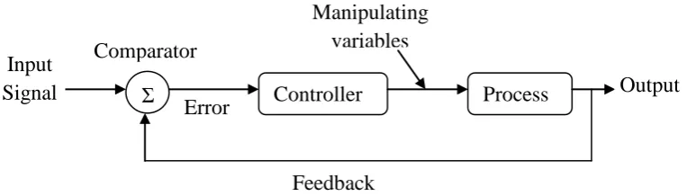
A closed-loop control system, known as a feedback control system is a control
system that has one or more feedback loops. In closed-loop control system, an output
of the system is feedback to the loops to compare the actual output with the desired
output. This comparison can reduce the error by automatically adjusting the systems
input, and produce more accurate result for the system. In addition, the closed-loop
control system able to increase the systems sensitivity, enhance robustness against
external disturbances and produce a reliable performance. Thus, it is a must to design
a controller for the said purpose. A good example of a controller is PID controller.
Figure 1.1: Feedback control system
PID controller, which consists of proportional, integral and derivative gain elements
that are commonly used in industrial processes due to its flexibility attributes. A
proportional band, the controller output is proportional to the error or a change in
measurement based on the controller. In addition, the proportional to the error at
instant time, t is called “present error”. Furthermore, the controller output in integral
action is proportional to the amount of time the error that can eliminate offset. The
proportional to the integral of the error up to the instant, t is interpreted as the “past”
error. Finally, the controller output in derivative action is proportional to the rate of
change of the measurement or error. The proportional to the derivative of the error at
the instant, t is interpreted as the prediction of the “future” error. The performance of
a PID controller is controlled by the choice of its parameter with some tuning. Bt
tuning the PID controller, the desired control performance can be obtained by
choosing suitable values for its adjustable parameter. As compared to the
well-known and simple structured fixed gain PID controllers, adaptive controllers are very
effective to handle the unknown parameter variations and environmental changes.
An adaptive controller consists of two loops, an outer loop or normal feedback loop
and an inner loop or parameter adjustment loop. Furthermore, the Model Reference
Adaptive Control (MRAC) refers to an adaptive system in which adaptive controllers
are designed by using a reference model to describe the desired characteristics of the
machine tool application to be controlled that provides a stability performance.
Besides that, the basic block diagram of MRAC system shown in Figure 2 shows that
ym(t) is the output of the reference model and y(t) is the output of the actual machine
An equation of this error is written by e(t) = y(t) – ym(t). So, MRAC can be applied
[image:21.595.152.486.153.305.2]in machine tool application in order to produce a better performance and accuracy.
Figure 1.2: Example of Model Reference Adaptive Control (MRAC) Scheme
1.2 Problem Statements
The demand for better tracking performance in machine tools stimulates the
improvement of machine tool technologies. A part included in the machine tool
technology is the machine tool controller. A coordinated advancement of the
different technology areas and good knowledge and understanding the factors that
contribute to the machine accuracy and speed is important. One measure of accuracy
is tracking performance that must be needed for machine tool application. The
factors that can reduce the tracking performance are:
(i) Mechanical structure
(ii) Friction Force
The mechanical structure can reduce the tracking performance of machine tool. The
mechanical of the system creates negatively to the dynamic and frequency response
function (FRF) of the machine. The mechanical resonances are occurred during the
movement of the machine tool and can reduce the stability of the system. The
presence of machine tool resonance will create a physical vibration of the movement
structure that can affect the tracking accuracy of a machine.
On the other hand, friction force is created between motor and support bearings of
electromechanical drive system in nonlinear circumstances. The friction forces result
a “quadrant glitches” in which accuracy of the system is disturbed. The glitches
occur during the changing direction of the axis movement of the system.
These factors can be reduced by designing a better controller but it will result in a
more complex control algorithm.
1.3 Objectives
The objectives of the project are:
i. To design a Model Reference Adaptive Control (MRAC) controller for
machine tool applications to improve tracking performance and transient
response.
ii. To validate the controller through simulation and experimental work.
1.4 Scope of Project
The scopes of the project are as follows:
i. The machine tool used is Ballscrew drive system XY table.
ii. The technique for design a controller is limited to PI controller and MRAC
controller.
iii. The method used in designing MRAC controller is Lyapunov approach.
iv. The controllers are validated through simulation and experimental work using
MATLAB and dSPACE software.
1.5 Organization of Report
This report focuses on designing a MRAC controller for obtaining precise position
and tracking accuracy of XY Table Ball Screw Drive system. The report is organized
as follows:
Chapter 2 discusses the literature review including introduction, why adaptive
control, components of Model Reference Adaptive Control (MRAC) controller,
MRAC modelling, stability analysis, system identification and summary.
Chapter 3 elaborates the project methodology including introduction, experimental
setup, software requirement, system identification and summary.
Chapter 4 discusses the design and development including machine tools, model
reference adaptive control (MRAC) design and MRAC simulation.
Chapter 5 discusses the result and discussion including MRAC diagram,
experimental data collected, response of the machine tool system analysis and
stability analysis.
Chapter 6 discussed the findings and the main results obtained with respect to
MRAC controller design and recommendations for future work.