Nanosecond colloidal quantum dot lasers
for sensing
B. Guilhabert,1∗C. Foucher,1A-M. Haughey,1E. Mutlugun,2,3,4Y. Gao,2J. Herrnsdorf,1H.D. Sun,5H.V. Demir,2,3M.D. Dawson1and N.
Laurand1
1Institute of Photonics, University of Strathclyde, Glasgow G4 0NW, UK
2Luminous!, Centre of Excellence for Semiconductor lighting and Displays, School of Electrical and Electronics Engineering, School of Physical and Mathematical Sciences,
Nanyang Technological University, 639798, Singapore
3Department of Electrical and Electronics Engineering, Department of Physics and UNAM -Institute of Material Science and Nanotechnology, Bilkent, Ankara, Turkey
4Electrical-Electronics Engineering, Abdullah Gul University, Kayseri, Turkey
5Division of Physics and Applied Physics, Centre for Disruptive Photonic Technologies (CDPT), School of Physical and Mathematical Sciences, Nanyang Technological University,
637371, Singapore
Abstract: Low-threshold, gain switched colloidal quantum dot (CQD) distributed-feedback lasers operating in the nanosecond regime are reported and proposed for sensing applications for the first time to the authors’ knowledge. The lasers are based on a mechanically-flexible polymeric, second order grating structure overcoated with a thin-film of CQD/PMMA composite. The threshold fluence of the resulting lasers is as low as 0.5 mJ/cm2 for a 610 nm emission and the typical linewidth is below 0.3nm. The emission wavelength of the lasers can be set at the design stage and laser operation between 605 nm and 616 nm, while using the exact same CQD gain material, is shown. In addition, the potential of such CQD lasers for refractive index sensing in solution is demonstrated by immersion in water.
© 2014 Optical Society of America
OCIS codes:(250.5590) Quantum-well, -wire and -dot devices; (140.3490) Lasers, distributed-feedback; (280.4788) Optical sensing and sensors.
References and links
1. Q. Sun, Y. Wang, L. S. Li, D. Wang, T. Zhu, J. Xu, C. Yang, and Y. Li, “Bright, multicoloured light-emitting diodes based on quantum dots,” Nature Photon.1, 717–722 (2007).
2. T. H. Kim, K. S. Cho, E. K. Lee, S. J. Lee, J. Chae, J. W. Kim, D. H. Kim, J. Y. Kwon, G. Amaratunga, S. Y. Lee, B. L. Choi, Y. Kuk, J. M. Kim, and K. Kim, “Full-colour quantum dot displays fabricated by transfer printing,” Nature Photon.5, 176–182 (2011).
3. S. Nizamoglu, G. Zengin, and H. V. Demir, “Color-converting combinations of nanocrystals emitters for warm-white light generation with high color rendering index,” Appl. Phys. Lett.92, 031102 (2008).
5. V. I. Klimov, A. A. Mikhailovsky, S. Xu, A. Malko, J. A. Hollingsworth, C. A. Leatherdale, H. J. Eisler, and M. G. Bawendi, “Quantization of multiparticle auger rates in semiconductor quantum dots,” Science287, 1011 (2000).
6. V. Klimov, A. A. Mikhailovsky, S. Xu, A. Malko, J. A. Hollingsworth, C. A. Leatherdale, H. J. Eisler, and M. G. Bawendi, “Optical gain and stimulated emission of nanocrystal quantum dots,” Science290, 314 (2000). 7. A. V. Malko, A. A. Mikhailovsky, M. A. Petruska, J. A. Hollingsworth, H. Htoon, M. G. Bawendi, and V. I.
Klimov, “From amplified spontaneous emission to microring lasing using nanocrystal quantum dot solids,” Appl. Phys. Lett.81, 1303 (2002).
8. S. Hoogland, V. Sukhovatkin, I. Howard, S. Cauchi, L. Levina, and E. H. Sargent, “A solution-processed 1.53µm quantum dot laser with temperature-invariant emission wavelength,” Opt. Express14, 3273–3281 (2006). 9. J. Schafer, J. P. Mondia, R. Sharma, Z. H. Lu, A. S. Susha, A. L. Rogach, and L. J. Wang, “Quantum dot
microdrop laser,” Nano Lett.8, 1709–1712 (2008).
10. V. M. Menon, M. Luberto, N. V. Valappil, and S. Chatterjee, “Lasing from InGaP quantum dots in a spin-coated flexible microcavity,” Opt. Express16, 19535–19540 (2008).
11. C. Dang, J. Lee, C. Breen, J. S. Steckel, S. Coe-Sullivan, and A. Nurmikko, “Red, green and blue lasing enabled by single-exciton gain in colloidal quantum dot films,” Nature Nanotechnology7, 335–339 (2012).
12. Y. Chen, B. Guilhabert, J. Herrnsdorf, Y. Zhang, A. R. Mackintosh, R. A. Pethrick, E. Gu, N. Laurand, and M. D. Dawson, “Flexible distributed-feedback colloidal quantum dot laser,” Appl. Phys. Lett.99, 241103 (2011). 13. F. Todescato, I. Fortunati, S. Gardin, E. Garbin, E. Collini, R. Bozio, J. J. Jasieniak, G. D. Giustina, G. Brusatin,
S. Toffanin, and R. Signorini, “Soft-lithographed up-converted distributed feedback visible lasers based on CdSe-CdZnS-ZnS quantum dots,” Adv. Func. Mater.22, 337–344 (2012).
14. V. C. Sundar, H. J. Eisler, T. deng, Y. Chan, and L. T. amd M G. Bawendi, “Soft-lithographically embossed multilayered distributed feedback nanocrystal lasers,” Adv. Mater.16, 2137–2141 (2004).
15. A. Rose, Z. Zhu, C. F. Madigan, T. M. Swager, and V. Bulovic, “Sensitivity gains in chemosensing by lasing action in organic polymers,” Nature434, 876–879 (2005).
16. Y. Yang, G. A. Turnbull, and I. D. W. Samuel, “Sensitive explosive vapor detection with polyfluorene lasers,” Adv. Funct. Mater.20, 2093–2097 (2010).
17. Y. Tan, C. Ge, A. Chu, M. Lu, W. Goldshlag, C. S. Huang, A. Pokhriyal, S. George, and B. T. Cunningham, “Plastic-based distributed feedback laser biosensors in microplate format,” IEEE Sensors J.12, 1174–1180 (2012).
18. C. Vannahme, M. C. Leung, F. Richter, C. L. C. Smith, P. G. Hermannsson, and A. Kristensen, “Nanoimprinted distributed feedback lasers comprising TiO2tin films: design and guidelines for high performance sensing,” Laser Photonics Rev.7, 1–7 (2013).
19. E. Mutlugun, P. L. Hernandez-Martinez, C. Eroglu, Y. Coskun, T. Erdem, V. K. Sharma, E. Unal, S. K. Panda, S. G. Hickey, N. Gaponik, and H. V. A. Eychmller, “Large-are (over 50cm x 50cm) freestanding films of colloidal InP–ZnS quantum dots,” Nano Lett.12, 3986–3993 (2012).
20. H. Mattoussi, J. M. Mauro, E. R. Goldman, G. P. Anderson, V. C. Sundar, F. V. Mikulec, and M. G. Bawendi, “Self-assembly of CdSe–ZnS quantum dot bioconjugates using an enginneered recombinant protein,” JACS122, 12142–12150 (2000).
21. D. R. Larson, W. R. Zipfel, R. M. Williams, S. W. Clark, M. P. Bruchez, F. W. Wise, and W. W. Webb, “Water-soluble quantum dots for multiphoton fluorescence imaging in vivo,” Science300, 1434–1436 (2003). 22. Y. Boucher, A. Deryagin, V. Kuchinskii, and G. Sokolovskii, “Near-threshold spectral and modal characterisitics
of a curved-grating quantum well distributed feedback,” Nanotechnology14, 615–618 (2003).
23. A. M. Haughey, B. Guilhabert, A. L. Kanibolotsky, P. J. Skabara, G. A. Burley, M. D. Dawson, and N. Laurand, “An organic semiconductor laser based on star-shaped truxene-core oligomers for refractive index sensing,” Sen-sors and Actuators B: Chemical185, 132–139 (2013).
1. Introduction
well as device demonstrations have followed including, among the latter, reports of whispering gallery mode lasers [7, 8, 9], vertical cavity surface emitting lasers [10, 11] and distributed feedback (DFB) lasers [12, 13, 14]. However, except in a limited number of cases such laser demonstrations have used ultrafast (10s of fs to a few ps) optical pulse excitation. While this is appropriate for photophysical studies and acceptable for initial development of the technology, operation with such short pulses has limited applicability because it necessitates the use of bulky and expensive pump lasers. To enable practical implementation of CQD lasers, operation with nanosecond or longer pulse duration is necessary. If low-threshold operation in such a regime can be achieved, it will then be possible to envisage pumping CQD laser systems with compact Q-switched solid-state lasers and possibly, for sufficiently low threshold, with laser diodes. The result will be a reduction in the footprint and cost of the CQD laser technology, bringing it closer to applications.
Herein, we report “hybrid plastic” CdSe/ZnS CQD lasers, i.e. made from an inorganic gain material in combination with a polymer cavity, operating in the nanosecond regime when gain-switched with 5ns-long pump pulses. One identified barrier to operation in such a temporal regime when using CQDs is the effect of Auger recombination, which basically limits the optical gain lifetime [5]. Circumventing or minimizing this problem necessitates optimization of the gain medium (e.g. using a high-density of CQDs [6]) and/or of the cavity (e.g. with a low-loss optical cavity [9]). In our work, CQD lasers with a few nanosecond-pulse duration are made possible by utilizing a planar distributed feedback cavity that includes a high surface quality thin film made of an optimized CQD-composite. Importantly, the planar thin film architecture of DFB lasers enables low-threshold oscillation thanks to a simple and efficient optical excitation of the gain medium as well as an adequate laser mode confinement. The resulting lasers have, to our knowledge, the lowest threshold for such a pulse duration (as low as 0.5mJ/cm2, 100kW/cm2), making them suitable for pumping with compact solid-state lasers. The DFB structure chosen here also enables emission wavelength versatility at the design stage through fine tuning of the cavity parameters: our lasers are shown to operate over a 11-nmspectral window in this way, while using the same CQD gain material. Furthermore, for ease-of-implementation, our DFB lasers are designed for vertical emission and, by way of example for applications, we demonstrate their potential for sensing.
In the following, the design structure of our DFB lasers is explained and details on sample fabrication as well as a description of the experimental set-ups are given in section 2. Optical characterization of thin films of CQD dispersed in poly(methyl methacrylate)(PMMA), which are used as gain material in our lasers, and their capability to sustain stimulated emission are presented in section 3.1. The experimental demonstration of laser operation under optical pumping in the nanosecond-regime is then reported and discussed in section 3.2. Finally, in section 3.3, proof-of-principle refractive index sensing is demonstrated by immersing lasers in water and monitoring the shift in the emission wavelength. This basic capability demonstration paves the way for further studies of the application of CQD lasers to (bio-) sensing.
2. Device structure, materials and methods
2.1. Laser structure
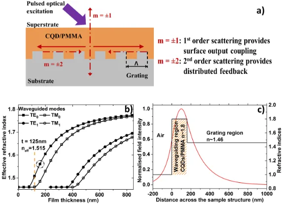
The lasers reported in this paper are based on a DFB cavity. The structure consists of a nano-patterned polymeric substrate overcoated with a thin film of CQD/PMMA composite. The superstrate, i.e., the medium above the gain layer, is either air or water (as explored in section 3.3). The nanostructure on the surface of the substrate is a 1-dimensional second order grating for the desired wavelength of operation (in the 600-620nmspectral region here). Some of the light generated in the CQD/PMMA thin film upon optical excitation is then guided in the film and interacts with the grating. If the film provides optical gain, then optical feedback generated by the second order of diffraction gives rise to laser oscillation, while the first order of diffraction leads to a vertical emission (i.e., normal direction to the film) of the laser output (Fig. 1(a)). The overall structure is designed so that the laser oscillates in a single transverse mode (TE0). This single mode design has been derived on the basis of the refractive indices of the CQD/PMMA system (n∼1.8) and of the polymeric substrate material (1.46). Figure 1(b) shows the dispersion curve of the first few possible modes, represented as the modal effective refractive index plotted versus the film thickness. The laser wavelength is given by the Bragg wavelength and is for a second order grating:λbragg=ne f f×Λ, where ne f f is the effective refractive index of the propagating mode in the slab waveguide formed by the gain and the grating materials andΛthe periodicity of the grating. The thickness of the film is chosen here to be around 130 and 160nmfor gratings with a 390 and 400nmperiodicity, respectively, in order to match the 611nmwavelength of maximum gain of the CQD films (see section 3.1). In that range of thickness only the TE0mode can oscillate. This idealized structure can be slightly altered in order to obtain different emission wavelengths. The normalised TE0transverse mode profile is represented in Fig. 1(c) for a structure with a film thickness of 160nm. Its overlap with the CQD-film (the gain region) is 35%, thereby enabling efficient amplification and hence low-threshold operation.
2.2. Materials and sample preparation
Fig. 1. a) Schematic of a DFB laser based on a second order grating, b) the effective refrac-tive index of the modes plotted against the thickness of a film of refracrefrac-tive index 1.8. For thicknesses between 130nmand 160nm, only the TE0mode can oscillate, c) Normalised TE0mode profile for a film thickness of 160nmmatching the propagation condition indi-cated in b) by the circle (ne f f∼1.566).
storage. The blending of the CQDs into a PMMA solution was carried out in air and at room temperature and ambient humidity level. First a solution of PMMA in chloroform/toluene was prepared using adequate amount of PMMA powder and an equal amount of chloroform and toluene. The solution was thoroughly mixed using a vortexer and a sonication bath. Then, 1mgof CQDs in solution were dried out from the toluene content using a membrane vacuum pump. An adequate volume of PMMA solution was then added to the dried CQDs followed by mixing and sonication bath treatment to ensure their full re-dispersion within the new solution. The study of stimulated emission relies on the coating of a cleaned glass slide (n∼1.45) by a thin film of CQD/PMMA material, subsequently annealed in air on a hotplate at 30◦Cfor 10 min. The cleaning procedure of the glass slide was carried out by subsequent baths in acetone, methanol and deionized water under sonification. Additionally, polymer substrates (NOA85 n∼1.46) were also used to form films of CQD/PMMA. Afterwards, the samples were cleaved using a diamond-tip pen. The surfaces of typical samples were inspected by atomic force microscope giving surface root mean square roughness of 5.6nmand 6nmover 20µm ×20 µm areas, respectively, for silica and polymer substrates. A representative film edge scanning electron microscope micrograph of the samples is given in Fig. 2. The thickness of the composite film was estimated to be around 155nm, which matches the design guidelines shown in Fig. 1.
[image:5.612.163.450.77.284.2]Fig. 2. Scanning electron microscopy images showing the edge of a representative cleaved film of CQD/PMMA composite on a Si/SiO2substrate.
A first short exposure (30s, at ∼26.5mJ/cm2) under UV was realized through the acetate sheet, the acrylate polymer film was then released from the silica master and a final UV cure followed to bring the full curing dose to 3.5J/cm2. To fabricate the DFB lasers, CQD/PMMA was spin-coated onto the acrylate polymer grating to form a film of the desired thickness. The film was then annealed in air on a hotplate at 30◦Cfor 10 min.
2.3. Experimental setups
Fig. 3. a) Optical pumping setup for amplified spontaneous emission, b) edge of the film under nanosecond excitation in the stimulated emission regime as seen by the collecting optical fiber (scale bar is 0.4mm), c) schematic of DFB laser characterisation, d) DFB laser under optical pumping (dichroic mirror removed) (scale bar is 10mm).
3. Experimental results and discussion
3.1. Photoluminescence and amplified spontaneous emission
The top and edge PL spectra of CQD films excited in the UV at 371nmwere first measured. The CQDs were at a concentration of 50mg/mL, dispersed in PMMA solution at 1.6mg/mL (50/1.6 w/r) and spin-coated on a glass substrate. The top emission PL of the film was recorded and shows that the emission of core/shell CQDs within a PMMA matrix peaks at a wavelength of 590 nm in accordance with the stated value in the data sheet (Fig. 4(a)). The edge PL of the sample is red-shifted by 7nm(to 597 nm) with respect to the top PL. This is caused by the re-absorption effects of the intrinsic emission as it propagates in the film due to the relatively small Stokes shift (∼20nm) of the CQDs. In addition, PL quantum yield (PLQY) was measured using an 8-inch integrating sphere and a continuous wave pump source emitting at 450 nm. The resulting PLQY for the aforementioned film of spin-coated CQD/PMMA nanocomposite is 15%.
[image:7.612.164.450.75.271.2]Fig. 4. a) Top and edge micro-photoluminescence spectra under 371nmoptical excitation of core/shell CQDs dispersed at a concentration of 50 mg/mLin a PMMA solution at 1.6mg/mL. The sample was processed by spin-coating on a silica substrate. b) Stimulated emission spectrum of the previous film under nanosecond optical pumping. The dashed line in both figures represents the peak wavelength of the stimulated emission spectrum.
Fig. 5. a) Transfer function of the ASE from CQDs/PMMA composite samples spin-coated on glass. These data show different CQD/PMMA w/r combination and how it affects their thresholds. b) Further details on the spectral emission of the ASE peaks for different com-position of materials.
[image:8.612.143.471.76.207.2] [image:8.612.150.465.313.444.2]3.2. Distributed feedback lasers demonstrations
Figure 6(a) shows the transfer function of a typical DFB laser made with a grating periodicity Λ=390nmand the optimized CQD/PMMA thin-film described previously as the gain layer. An established laser regime with a 0.50-mJ/cm2 threshold is measured for an emission at 610nmas depicted in Fig. 6(a) and (b), respectively. The spatial distribution of the intensity of the emitted laser beam, pictured in the inset of Fig. 6(a), follows the expected fan-shape typical of a one-dimensional vertical emitting DFB laser. Similar results are obtained for a 400-nm-periodicity DFB laser (Fig. 6(c)). In that case, the threshold is 0.85mJ/cm2. One can notice a transition region near but below threshold (pump fluence between 0.60mJ/cm2and 0.85mJ/cm2) where the increase in intensity is not linear as opposed to the established regime (fluences≥0.85mJ/cm2). A closer inspection of the spectrum evolution is given in Fig. 6(d) (in logarithmic scale). Stimulated emission with a narrow spectrum is already taking place for pumping fluence between 0.60 and 0.70mJ/cm2. The resulting “soft” threshold is sometimes observed in DFB lasers made of high-gain thin films and is an indication that a significant amount of spontaneous emission is coupled into the laser mode [22].
Fig. 6. DFB laser demonstrations made using a polymer grating of refractive index 1.46 with core/shell CQDs at a concentration of 50mg/mLin a PMMA host matrix at 1.6mg/mL(50/1.6 w/r) with periodicity ofΛ=390nm(a and b) andΛ=400nm(c and d). a) and c) are the power transfer functions and b) and d) are the emission spectra of the DFB lasers.
[image:9.612.150.465.279.515.2]the lowest threshold fluence is found for the oscillation wavelength closest to the maximum of the peak of the stimulated emission spectrum. Figure 7(c) shows the recorded laser pulse from the optical excitation and a CQD DFB laser addressed with a fluence several times the threshold, respectively. These pulses were recorded using a 1-ns-rising time fast photodiode connected to a 500-MHzoscilloscope (equivalent rising time of 0.7ns). As stated previously, the optical pump delivers pulses of∼5nsFWHM; in comparison, the DFB laser emits optical pulses∼2.8-ns-long. Lastly, Fig. 8 summarizes the threshold fluences (closed symbols) and power density level (opened symbols) of different published reports of CQD lasers including whispering gallery modes [7, 8, 9], vertical cavity surface emitting lasers [11] and DFB [12, 13] compared to those of the lasers reported here. It is thus shown that this work represents state-of-the-art CQD lasers with a threshold close to 100kW/cm2.
Fig. 7. a) Discrete tuning demonstration of the distributed feedback lasers based on CQD/PMMA gain layer by varying its film thickness or the grating period (390 and 400nm). The ASE spectrum is plotted alongside to guide the reader for the maximum of the gain spectrum. b) Summary of the measured threshold to the lasing wavelength. The highlighted region is the 1/e2of the stimulated emission spectrum in the saturated regime. c) Optical pulse duration of the pump and CQD DFB laser.
3.3. Refractive index sensing
[image:10.612.163.449.229.462.2]Fig. 8. Comparison of reported laser thresholds for devices based on CQDs as the gain material expressed in terms of fluence (top section) and power density (bottom section) against the pump pulse duration. Data shown above represent: VCSEL (diamonds), WGM (triangles), DFB lasers (circles) and this work (stars).
Fig. 9. a) Schematic of refractive index sensing of liquid medium using CQD/PMMA DFB lasers, b) bulk refractive index sensing results of deionised water (n≈1.33), c) wavelength and emission intensity of a DFB laser cycled between air and water media.
4. Conclusion
We have reported on the design and fabrication of DFB lasers made with CQDs as gain materials dispersed in a PMMA matrix to obtain high quality films. Stimulated emission and single transverse mode DFB lasers are demonstrated under 5nspulsed excitation at 355nm for the first time to the authors’ knowledge. DFB lasers with oscillation thresholds as low as 0.50 mJ/cm2 were achieved for 610 nm emission with a FWHM linewidth below 0.3nm. Optical pumping of such plastic CQD devices with compact solid-state lasers is therefore already possible. Laser emission over 11nm, from 605 to 616nm, is also shown by tuning the cavity parameters, e.g., gain material thickness and/or the periodicity of the DFB grating. Finally, the first step towards the usage of CQD DFB lasers in a “real-world” application was taken with the demonstration of laser operation in a liquid environment. A 4nmred-shift of the DFB laser emission was detected upon immersion in water. Overall, this study demonstrates the potential of CQD lasers for future applications.
Acknowledgments
[image:12.612.164.450.77.261.2]