Influence of elevated radiative lifetime on
efficiency of CdSe/CdTe Type II colloidal
quantum dot based solar cells
Leontiadou, M, Tyrrell, EJ, Smith, CT, EspinbarroVelasquez, D, Miloszewski, JM,
Walsh, TJE, Binks, D and Tomic, S
http://dx.doi.org/10.1016/j.solmat.2016.01.018
Title
Influence of elevated radiative lifetime on efficiency of CdSe/CdTe Type
II colloidal quantum dot based solar cells
Authors
Leontiadou, M, Tyrrell, EJ, Smith, CT, EspinbarroVelasquez, D,
Miloszewski, JM, Walsh, TJE, Binks, D and Tomic, S
Type
Article
URL
This version is available at: http://usir.salford.ac.uk/id/eprint/37795/
Published Date
2016
USIR is a digital collection of the research output of the University of Salford. Where copyright
permits, full text material held in the repository is made freely available online and can be read,
downloaded and copied for noncommercial private study or research purposes. Please check the
manuscript for any further copyright restrictions.
In
fl
uence of elevated radiative lifetime on ef
fi
ciency of CdSe/CdTe Type
II colloidal quantum dot based solar cells
Marina A. Leontiadou
a, Edward J. Tyrrell
b, Charles T. Smith
a,
Daniel Espinobarro-Velazquez
a, Robert Page
c, Paul O'Brien
c, Jacek Miloszewski
b,
Thomas Walsh
b, David Binks
a, Stanko Tomi
ć
b,naSchool of Physics and Astronomy & Photon Science Institute, University of Manchester, Manchester M13 9PL, United Kingdom bJoule Physics Laboratory, School of Computing, Science and Engineering, University of Salford, Manchester M5 4WT, United Kingdom c
School of Chemistry, University of Manchester, Manchester M13 9PL, United Kingdom
a r t i c l e i n f o
Article history:
Received 11 July 2015 Received in revised form 11 December 2015 Accepted 17 January 2016
Keywords:
Efficiency Solar cells
Colloidal quantum dots Core/shell structure
a b s t r a c t
Colloidal quantum dots (CQDs) are promising materials for solar cells because their optoelectronic properties are easily adjusted by control of their size, structure and composition. We present calculations of the band gap and radiative lifetime for varying core diameter and shell thickness of CdSe/CdTe core/ shell Type II CQDs using a combination of single particle (2,6)-band kpand many-electron confi g-uration interaction (CI) Hamiltonians. These calculations are validated by comparison with experimental absorption spectra and photoluminescence decay data. The results are then incorporated into a model of photovoltaic efficiency which demonstrates how the overall performance of a solar cell based on Type II CQDs is affected by changes in the core/shell geometry. The largest effect on photovoltaic efficiency is found to be due to the longer radiative lifetime produced by increasing the shell thickness.
&2016 Published by Elsevier B.V.
1. Introduction
Colloidal quantum dots (CQDs) are nanoscale crystals of semi-conductor that are sufficiently small to confine charge carrier wave functions. This effect allows the effective band gap,Eg, of CQDs to be size-tuned which, coupled with the facile and inexpensive solution-based techniques by which they can be synthesised and processed, makes them promising photo-absorbing species for solar cells[1], as well as having other application in displays[2,3], lighting[3,4]and photorefractive devices[5]. The appeal of CQDs for solar energy conversion is further increased by the possibility of the efficient generation of more than one electron–hole pair per absorbed photon, by a process known either as multiple exciton generation or carrier multiplication [6]. Progress in CQD-based solar cells has been particularly rapid in recent years[1]with the development of effective surface passivation techniques using halide ions, resulting in enhanced efficiency with the record under unconcentrated sunlight currently standing at 9.9%[7].
Reducing the size of CQDs increasesEgrelative to its bulk value. This means that size-tuning can be used to optimise the effective optical gap of CQDs for solar conversion if they are composed of a
material which has a bulk Eg that is too small for effective exploitation of the solar spectrum. Examples of such CQD mate-rials include PbS and PbSe which have bulk band gaps of 0.41 eV
[8]and 0.28 eV[9], respectively. The corollary of this is that size tuning cannot be used to reduceEgtowards the optimum value. However, a shell of a different semiconductor material can be grown around a CQD, and this so-called core/shell geometry allows the photo-physical properties to be controlled in a different way to size-tuning. For instance, for some combinations of core and shell material, the band offsets are such that a“Type II” het-erojunction is formed, which causes electrons and holes to localise in different regions (in a Type I configuration, both charge carriers localise to the same region). The absorption edge of such a Type II core/shell CQD corresponds to a transition from the valence band maximum (VBM) of one of the materials to the conduction band minimum (CBM) of the other, and the energy of this transition may be less than the bulk band gap of either of the materials that comprise the CQD [10]. A Type II structure thus allows Eg to be reduced towards the optimum, but it will also affect photo-physical properties of CQDs in other ways that determine their efficacy as the photo-absorbing species in a solar cell. In particular, localisation of the electron and hole into different regions of the CQDs reduces the overlap of their wave functions. This will tend to increase the radiative recombination lifetime,
τ
rad:, and henceContents lists available atScienceDirect
journal homepage:www.elsevier.com/locate/solmat
Solar Energy Materials & Solar Cells
http://dx.doi.org/10.1016/j.solmat.2016.01.018
0927-0248/&2016 Published by Elsevier B.V.
increase the probability that photo-generated charges will escape the CQD and be collected at the electrodes of the cell.
Optimisation of the design of a Type II CQD for application as the photo-absorbing species in a solar cell requires an under-standing of how combinations of core diameter and shell thickness simultaneously affect the properties of CQDs important to photo-voltaic performance. The properties of Type II CQDs have been calculated previously by a number of techniques including effec-tive mass modelling[11,12]and a quantum Monte Carlo approach
[13], with most of this work focusing on CQDs composed of the cadmium chalcogenide materials for which synthesis techniques are very well-developed. We have recently shown [14] that the most accurate description of Type II Cd-based CQDs requires the incorporation in the model of both configuration interactions and polarisation effects at the CQD surface.
In this work, we use this model to investigate how bothEgand
τ
rad:change with core diameter and shell thickness for CdSe/CdTecore/shell Type II CQDs. The results of these calculations are vali-dated by comparison with experimental data, and are also incor-porated into a model of photovoltaic efficiency that describes how the overall performance of a cell based on Type II CQDs is affected by changes in the core/shell geometry.
2. Methodology
2.1. Theory
In order to describe the electronic structure of CdSe/CdTe CQDs, we perform calculations usingkptheory in conjunction with the CI method. The (2,6)-bandkpHamiltonian,H^ðμÞ, for spherically symmetric CQD heterostructures is used to calculate single-particle states in core/shell CQDs; this theory takes into account the complex band mixing, the spin–orbit interaction, and correct operator ordering at the core/shell and shell/colloid hetero-interfaces. The Schrödinger equation for the single-particle states can be written as follows:
^
HðμÞ
φ
ðnjmpμÞ ¼EnjpðμÞφ
ðnjmpμÞ ð1Þwhere
μ
¼ fe;hg denote electron or hole single-particle states,φ
ðμÞnjmpis the single-particle wave function,E ðμÞ
njpis the single-particle
energy,nis the principle quantum number,jis the total angular momentum,mis thez-component of the total angular momen-tum, andpis the eigenvalue of the parity operator. In the (2,6)-bandkptheory the electron (hole) wave function is given by:
φ
e njmpðrÞ ¼X1=2
Jz¼ 1=2
Fe1;=njmp2;J
zðrÞu e
1=2;Jz ð2Þ
and
φ
h njmpðrÞ ¼X3=2
J¼1=2
XJ
Jz¼ J
FhJ;;Jnjmp
z ðrÞu h
J;Jz ð3Þ
where uμJ;J
z represents the Bloch function of the conduction (valence) band,JandJzare the Bloch function angular momentum and its z-component, respectively, and FμJ;J;njmp
z ðrÞ are envelope functions which contain the angular and radial dependences of the wave functions; full definitions are given in Refs.[11,14,15]. Due to the spherical symmetry of the system, the eigen-energies areð2j
þ1Þfold degenerate with respect to the quantum numberm. The eigen-energies of single-particle levels are calculated by numeri-cally solving the equations resulting from imposing continuity of the radial wave functions and radial component of the probability current across the heterointerfaces[15]. The material parameters used to calculate single-particle states are listed in Ref. [14].
We denote single-particle states using the spectroscopic notation
nlðjμÞ wherel¼s;p;d;…represents the lowest value of the orbital angular momentum in the wave function. The eigenvaluepof the parity operator takes the values 1 and 1 for even and odd symmetry states, respectively. The dielectric constant varies sig-nificantly between the CQD and the surrounding colloidal mate-rial. Such variation produces very strong dielectric confinement and its effect on the excitonic structure cannot be neglected. In the presence of a spatially varying dielectric constant, the exciton Hamiltonian may be written as:
^
HX¼H^ e
þH^hþVcðre;rhÞþVsðreÞþVsðrhÞ ð4Þ
whereVcis the interparticle Coulomb potential andVsis the self-polarisation potential due to the interaction of a carrier with its own polarisation charge. In contrast to epitaxial QDs[16], the large dielectric mismatch between CQDs and the surrounding solvent necessitates the inclusion of self-polarisation terms in the Hamil-tonian. We note thatVc¼VpþVd where Vd is the direct inter-particle Coulomb potential and Vp is the interface polarisation potential [11]. We calculate the potentials Vc and Vs using the numerical model of Bolcatto and Proetto forfinite size dielectric interfaces[17].
Correlated exciton states are solutions of the Schrödinger equation
^
HX
Ψ
L;LXz¼EXΨ
L;LXz ð5ÞwhereLis the total exciton angular momentum, Lz is itsz -com-ponent andEXis the exciton eigen-energy. To construct excitonic states, we couple single particle states in terms of angular momentum rather than parity. Using the solutions of Eq. (1),
φ
ðμÞnjmp¼ jnjmp〉, we define the new ket notation,jnjmp〉, expressed
in terms of both total angular momentumjand the lowest value of orbital angular momentuml. In such notation the transformation betweenl,jandpis given asl¼jp=2 for electrons andl¼minð
jþp=2;jj3p=2j Þ for holes, where p¼ þ1ð1Þ for even (odd) states regardless of whether electron or hole states are considered
[15]. We expand the exciton wave function in terms of uncorre-lated electron–hole pair (EHP) states as:
Ψ
L;LzX ¼
X
β
cβjnelejemenhlhjhmh;L;Lz〉 ð6Þ
where
jnelejenhlhjh;L;Lz〉¼ X
me;mh
CL;Lz
jeme;jhmhjnelejeme〉jnhlhjhmh〉 ð7Þ
andCL;Lz
jeme;jhmh and cβ represent a Clebsch–Gordan coefficient and the expansion coefficients (character) of a particular EHP state labelled by
β
, respectively. The exciton Hamiltonian is then diag-onalised in the basis of EHPs tofind the exciton energies and wave functions; this is sometimes called direct diagonalisation or the configuration interaction (CI) method[16].2.2. CQD synthesis
The CQDs were synthesised via the hot injection method using dual precursors. The CdSe cores were grown with a zinc-blende crystal structure following the method reported in Ref.[18], while the CdTe shell was grown by the dropwise method previously reported in Ref.[19]. After completion of the shelling process the CQDs were cooled at room temperature and stored under nitrogen.
2.3. Optical characterisation techniques
For optical characterisation the samples were placed in 10 mm path length quartz cuvettes (Starna) and diluted with toluene. The steady state absorption and the PL spectra were measured with
M.A. Leontiadou et al. / Solar Energy Materials & Solar Cells∎(∎∎∎∎)∎∎∎–∎∎∎
the use of a Perkin Elmer Lambda 1050 UV/Vis/NIR spectrometer and a Horiba Jobin Yvon Fluorolog model iHR(FL3-22)
spectro-fluorometer, respectively. The PL excitation wavelength was 450 nm with a bandwidth of 3 nm. Typical absorbance and PL spectra for CdSe, CdTe, and CdSe/CdTe CQDs are shown inFig. 1.
The PL time decay measurements were recorded using a time correlated single photon counting (TCSPC) system. A mode-locked Ti:sapphire laser (Mai Tai HP, Spectra-Physics) was used to gen-erate 100 fs pulses at 80 MHz repetition rate and 820 nm wave-length. The repetition rate was reduced to 2 MHz by an acousto-optic pulse picker (APE Pulse Select), and the initial output was converted to 410 nm via second harmonic generation (APE Har-moniXX). These pulses were used to excite the sample with an average excitation power of 2.5 mW, with a spot size of 2.8 mm and hence afluence of approximately 20 nJ/cm2. The PL emission
of the sample was directed into a monochromator (Spex 1870c) and detected by a multi-channel plate (Hamamatsu R3809U-50). The TCSPC electronics were from Edinburgh Instruments.
3. Results and discussions
3.1. Absorption edge wavelength of CdSe/CdTe Type II CQDs
We proceed our analysis with the examination of the influence of CdSe/CdTe core/shell CQD morphology on the variation of the
first exciton peak in the absorption spectra, which corresponds to excitation of the 1Se1=21S
h
3=2 state. As afirst step, we validate our theoretical methodology,Section 2.1, based on the combination of (2,6)-band kp and CI Hamiltonians, against available experi-mental and theoretical results on CdSe and CdTe core only CQD, as they are the constituent materials of our core/shell structure.Fig. 2
shows variation of the 1Se1=21S
h
3=2exciton energy as a function of CdSe and CdTe QD radius,ac, respectively. Solid symbols represent experimental results from several independent measurements from different groups and the line is an empirical inverse poly-nomialfitting curve,E1S1=21S3=2
X ðacÞ ¼E
bulk
g þðAa
2
cþBacþCÞ 1
, to this experimental data proposed by de Mello Donega in Ref. [20], where A, B, and C are fitting parameters. Results of 1Se1=21S
h
3=2 exciton energies predicted by our calculation are shown on the same figures and exhibit excellent agreement with the experi-mental measurements [21–30]. Such agreement confirms the accuracy of our methodology and parameter set for the lowest
excitonic state in both CdSe and CdTe CQDs over a wide range of CQD sizes.
Having been validated for core-only CQD structures, we now employ our method to describe CdSe/CdTe core/shell Type II CQD structures. The remaining question when modelling the system of core/shell structures is the parametrisation of the valence band offset (VBO) between core and shell materials, in our case CdSe and CdTe, respectively. From our previous analysis[14]of the variation of 1Se1=21S
h
3=2 and 1S
e
1=22S
h
3=2 excitonic energies with the shell thickness in CdTe/CdSe core/shell CQD, we have estimated the VBOCdTe=CdSe¼0:4 eV. We have assumed the same VBO for inverse structures, i.e., for CdSe/CdTe core/shell CQD considered here.
In contrast to core-only CQDs, the size dependence of 1Se1=21
Sh
3=2exciton energies in core/shell CQDs is more complex and it is not possible to capture its trend by simple polynomial fitting curve. Fig. 3shows the shell thickness, as, dependence of the 1
Se1=21S
h
3=2 absorption wavelengths for CdSe/CdTe core/shell CQDs for different core radii,ac, ranging fromac¼1.5 nm to 2.5 nm.
Also shown inFig. 3are experimental data for a CdSe core of 1.7 nm radius, as measured by transmission electron microscopy, and different CdTe shell thicknesses [31,45]. Good agreement is seen between the calculated energy of the 1Se1=21S
h
[image:4.595.317.559.52.452.2]3=2exciton and Fig. 1.Absorption (full lines) and PL (dashed lines) spectra for typical CdSe (red)
and CdTe (black) core only CQDs and CdSe/CdTe core/shell CQDs (blue). The core radius was 1.6 nm for the CdTe CQDs and 1.7 nm for both the CdSe core only and the core/shell CQDs; the CdTe shell thickness was 0.9 nm. (For interpretation of the references to colour in thisfigure caption, the reader is referred to the web version of this paper.)
Fig. 2.Variation of the 1Se
1=21Sh3=2exciton energy as a function of CQD core radius,
ac, in (a) CdSe and (b) CdTe CQDs: experimental results (black square symbols), de
[image:4.595.48.289.55.222.2]the spectral position observed for thefirst absorption peak, further validating our theoretical approach.
We can clearly distinguish between two trends in the 1Se
1=21
Sh3=2absorption wavelengths in the region of shell thicknesseso 0:5 nm and for shell thicknesses 40:5 nm. For the CQDs with shells of thickness approximately or less than 0.5 nm, we can see that (i) the 1Se1=21S
h
3=2absorption wavelengths are approximately linearly dependent on as, suggesting strong influence of the dielectric confinement on 1Se1=21S
h
3=2 excitons and their wave-lengths in this region and (ii) as the core size, ac, increases the gradient of the 1Se1=21S
h
3=2 absorption wavelength vs. as curves decreases. We explain such non-monotonic behaviour in terms of the changing localisation regime of the 1sh
3=2single-particle hole, in the correlated 1Se1=21S
h
3=2exciton, as the CQD dimensions change
[14]. The lower gradient of the curves for shell widthso0:5 nm is due to the fact that the 1sh
3=2hole is in the delocalised regime, i.e., its probability density is spread over the whole heterostructure and its energy is mainly determined by the global confinement provided by the QD potential well of radiusacþas. In this regime
the size dependence of the hole confinement is closer to that of one confined in a core-only QD. For the QDs with shells of width greater than 0.5 nm, we can see that the 1Se1=21S
h
3=2 absorption wavelengths again acquire a trend that can be described by a quadratic polynomial function. Asasincreases, for a particular core size, the 1sh
3=2single-particle hole localises in the shell fully so the absorption wavelength is again more strongly affected by the effect of shell thickness on the confinement energy of 1sh
3=2. This behaviour is closer to the strong confinement regime in a core/ shell heterostructure. Maps of the absorption wavelength against CQD core/shell dimensions, as depicted in Fig. 3, can only be obtained numerically and should be of use to experimentalists studying such systems.
3.2. Radiative lifetimes in CdSe/CdTe CQDs
In order to assess the variation of the radiative times,
τ
rad:, withthe core sizes,ac, and shell thicknesses,as, we use the following expression:
1
τ
rad:¼dX
3
F2ne2
πε
0m0c3ℏ2EXEPjPXj2 ð8Þ
wheren is the refractive index of the colloidal material,eis the electron charge,
ε
0 is the permittivity of free space, m0 is theelectron rest mass,cis the speed of light,ℏis the reduced Planck constant, andEP¼2P2=m0, where Pis the optical dipole matrix element of the bulk material at the
Γ
point. In the expression abovejPXj is the modulus of excitonic dipole matrix element andEXis the excitonic energy, obtained both from the CI calculation, anddXis the integer number representing the degree of degen-eracy of a particular excitonic state. For the 1Se
1=21S
h
3=2 exciton considered belowdX¼8. The expression for dielectric screening of spherical core/shell QDs is given asF¼3
ε
coll:=ð2ε
coll:þε
QDÞ, whereε
QD is the dielectric constants the dot andε
coll: is the dielectricconstant of the surrounding medium.
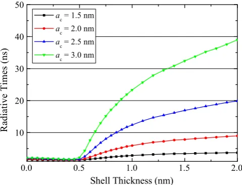
Fig. 4 shows the mean radiative lifetime of the 1Se1=21S
h
3=2 exciton in CdSe/CdTe CQDs as a function of shell thicknessasfor several different core radii. The most noticeable feature is the sudden increase in
τ
rad: at aroundas0:5 nm. In comparison tocore-only CQDs, in which the value of 1Se
1=21S
h
3=2excitonic radia-tive time,
τ
rad:; changes relatively weakly with the CQD size [32,33], in core/shell structures it is possible to increase this radiative time over one order of magnitude with suitable change in the core and shell sizes. Several observations regarding the trend inτ
rad: in CdSe/CdTe core/shell Type II CQDs can be madehere: (i) again as in the case of the absorption wavelength, shown inFig. 3, we can distinguish clearly between two different regions of the shell thicknessesaso0:5 nm andas40:5 nm. In the region
ofaso0:5 nm the whole CQD system behaves similar to core-only
CQDs, since both electron and hole correlated charge densities are either largely confined in the core region or just start to delocalise over the whole CQD structure. In this region the optical dipole matrix element,jPXj, is strong while the magnitude of bothjPXj
and EX changes very little with the overall sizes of QDs, which explains the almost constant
τ
rad:. (ii) As shell thicknesses increase,and in particular beyond as41 nm, the hole states become
strongly confined in the shell region. Here dielectric confinement does not have enough strength to overcome the confinement imposed by the Type II aligned valence band edge of CdTe, so that the exciton reaches the strong confinement regime. Consequently, the electron–hole wave function overlap is dramatically reduced, andEXis mainly now determined by the variation of the 1s
ðhÞ
3=2hole confinement withas. Foras41 nm,
τ
rad:continues to increase, butmore slowly, reaching values that are about one order of magni-tude greater than those for core-only CQDs. For all shell thick-nesses, a monotonic trend to larger
τ
rad: with increasing core sizeis also observed. It is interesting to observe that for CdSe/CdTe Type II CQDs the value of
τ
rad: increases over“only”one order of [image:5.595.41.278.55.250.2]magnitude while in other systems, such as epitaxially grown Type Fig. 3.Core radius,ac, and shell thickness,as, dependence of the 1S1e=21Sh3=2exciton
[image:5.595.307.547.57.240.2]peak in the absorption spectra of CdSe/CdTe core/shell CQDs. Also shown for comparison are experimental data from Ref.[31](squares) and Ref.[45](triangles).
Fig. 4.Plot of radiative lifetime against shell thicknessesac¼1:5;2:0;2:5 and
3.0 nm CdSe/CdTe CQDs, calculated using the CI method.
M.A. Leontiadou et al. / Solar Energy Materials & Solar Cells∎(∎∎∎∎)∎∎∎–∎∎∎
II InAs/GaAs/GaAsSb, a Type II structure the radiative times can increase over three order of magnitudes[34,35]. This difference in behaviour is attributed to the absence of significant dielectric confinement in epitaxially grown QDs, compared to CQDs.
The interplay between the excitonic energy, radiative times and absorption characteristics is intimately connected by the magni-tude of the excitonic optical dipole. In the Type-II configuration, as we have shown previously [36,37], the electron and hole are spatially separated, that is the wavefunction overlap becomes smaller when compared with the equivalent Type I structure. However, our previous analysis[36]suggests that the reduction of the absorption strength due to Type II alignment compared to the Type-I configuration is evident at the absorption edge while overall absorption characteristics are similar. However this change in absorption characteristics may reduce the overall efficiency of CQD solar cells, and will be discussed elsewhere.
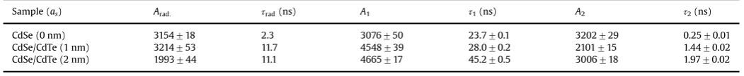
As for the calculations of the band gap described above, we also validate the values of radiative lifetime produced by our model by comparing them to experimental data. Fig. 5 shows example experimental PL decay transients for CdSe core-only CQDs, and for CdSe/CdTe CQDs comprising the same core and two different CdTe shell thicknesses. Thefirst absorption peak for these CQDs, which corresponds to the 1Se1=21S
h
3=2 exciton, was observed at 555 nm, 630 nm and 713 nm. Using the data presented in Figs. 2and3, these wavelengths indicate that the core radius is 1.6 nm and the shell thicknesses in the two CdSe/CdTe CQD samples are 1 nm and 2 nm, respectively. In each case, the PL decay transient is not mono-exponential in form, indicating that recombination dynamics are significantly affected by surface trapping[33,38,39]. The transients are well-described by a tri-exponential decay function yðtÞ ¼Arad:expðt=
τ
rad:ÞþA1expðt=τ
1ÞþA2expðt=τ
2Þ where t is the time and Arad:, A1, A2,τ
1 andτ
2 are the fittingparameters while the
τ
rad:is the radiative time. Similar behaviourhas been reported previously for CdSe[40–42], CdTe[33,40], CdTe/ CdSe[40]and CdSe/ZnS CQDs[43]. The tri-exponential form of the decay has been explained by Gong et al.[40]with a model that includes capture and escape from a shallow trap state related to an under-coordinated surface atom. Recent calculations[44]based on an Auger-mediated trapping model have identified under-coordinated Te atoms on the surface of CQDs as the source of hole-traps at an energy just 50 meV above the VBM, from which thermally excited escape is thus possible. In this model, one of the three time constants can be identified directly with
τ
rad:, assumingthat the fraction of CQDs that do not emit at all are primarily responsible for the quantum yield being less than unity[40]. We thereforefixed one of the time constants of a tri-exponential decay function to be equal to the calculated value
τ
rad:andfitted it to theexperimental PL decay data, with all otherfitting parameters free to vary. As shown in Fig. 5, this procedure resulted in excellent agreement between the data and thefit, demonstrating that the values of
τ
rad:calculated are consistent with experiment.The parameter values resulting from this fitting process are given inTable 1. In comparison, for a 1.7 nm radius CdSe core Chen et al.[45]also report a non-monoexponential PL decay transient, to which theyfit a biexponential function. The major component of thisfit has a lifetime of 18 ns, which is comparable to the value of
τ
1given inTable 1for the CdSe core only CQD. Chen also reportsthat the lifetime corresponding to this major component increases to 29 ns on the addition of a 1.870.1 nm thick CdTe shell, which is bounded by the values of
τ
1 for shells of 1.070.2 nm and270.2 nm thickness given in Table 1. The results described by Chen et al.[45]for a similar CdSe/CdTe CQD are thus consistent with the ones observed for our samples.
3.3. Solar cell efficiency
A limit for the theoretical maximum efficiency of a conven-tional solar cell can be calculated using the “detailed balance”
model [46], where whilst in thermal equilibrium under solar illumination, four unavoidable losses [47,48] are considered: (1) photons with energy below Eg are not absorbed; (2) carrier energy in excess of the bandgap is lost as heat; (3) thermodynamic loss—the available energy (Gibbs free energy or chemical poten-tial) of the thermalised excited states is always less than the internal energy, with the consequence that the photovoltage (or, output chemical potential) must be less thanEg; and (4) radiative recombination: a small fraction of the excited states radiatively recombine with the ground states at maximum power output.
The wavelength-dependentflux of solar radiation is integrated such that all photons with energy aboveEgproduce a single exciton at the band edge, producing a photo-generated current density given byIpg
¼eRE1
g
ϕ
ðhν
Þdðhν
Þwhereϕ
ðhν
Þ is the spectral photonflux density. This is offset by a loss of photogenerated current due to recombination, given by modelling black body radiation of the solar cell at room temperature: Ir¼ ð2π
e=h3c2ÞR1 Egfðh
ν
Þ2=exp½ðh
ν
eVÞ=kBT1gdðh
ν
Þ, [image:6.595.49.288.418.594.2]where h is Planck's constant, kB is Boltzmann's constant, T is the temperature (set to 300 K here) andVis the operating voltage of the cell.Vis assumed to be equal to a constant quasi-Fermi level separation and is numerically optimised to give the maximum efficiency, which is Fig. 5.Experimental photoluminescence decay transients (black) for CdSe
core-only CQDs withac¼1.6 nm, and CdSe/CdTe CQDs made from the same cores and with shell thickness of 1 nm and 2 nm. Also shown are tri-exponentialfits (red) to the data for which one of the time constants has been set to the calculated value of
τrad:for that core size and shell thickness. (For interpretation of the references to
colour in thisfigure caption, the reader is referred to the web version of this paper.)
Table 1
Parameters yielded from thefits shown inFig. 5.τrad:(ns) arefixed to calculated values.
Sample (as) Arad: τrad(ns) A1 τ1(ns) A2 τ2(ns)
[image:6.595.40.566.694.748.2]the ratio of output power to input power, given by
η
pv¼ ðIpgIrÞV=Ee, whereEeis the total solar irradiance. Here the total irradiance and solarflux are set to the AM1.5G solar spectrum[49]. Full details of the model can be found elsewhere[50].
We consider a fifth loss in the system which utilises the probability, Pesc:, of a cooled exciton escaping from a CQD and
contributing to the photocurrent before radiative recombination occurs. This can be expressed in terms of the characteristic lifetime of the escape process,
τ
esc:, and the radiative lifetime,τ
rad:, asPesc:¼
τ
1 esc:τ
1 rad:þτ
esc1:ð9Þ
For core sizes of 1.5 nm and 2 nm the efficiencies predicted by this model for solar cells utilizing CdSe/CdTe CQDs as the absorbing species are given inFig. 6with shell thicknesses up to 2 nm and
τ
esc:varying from 0.3 ns, indicating fast charge transfer as reportedby some authors [51–53], to 100 ns. Also shown is the thermo-dynamic efficiency limit where
τ
esc:¼0 and all charges escape theCQD. The optical band gaps used for these core sizes were those given inFig. 3, and the radiative lifetimes for a given shell thick-ness in Fig. 4. The predicted efficiency of the device increases significantly with the thickness of the CdTe shell for both core sizes, primarily attributable to the change in radiative lifetime. As expected a long carrier escape lifetime can significantly reduce this efficiency, and so will be a crucial element to the effectiveness of any devices hoping to utilise thick shells, and poses a particular challenge to the preparation and environment of the CQDs. Effective passivation methods such as bulky ligands, surface treatment or additional shells which can dramatically increase the quantum yield of CQDs[39,54,55]have been shown to sometimes hinder charge extraction[51], and dramatically reduce the yield of photovoltaic devices where carriers are Coulombically bound to the CQD–surface molecule interface unless operated with an externalfield[56,57].
4. Conclusions
Using a combination of kptheory and the CI method, the change in optical gap of CdSe/CdTe core/shell Type II CQDs has been predicted for varying core diameter and shell thickness. We have shown that the rate of change varies significantly as the hole states become strongly confined in the shell region, which was shown to occur when the shell thickness begins to exceed 1 nm.
This localisation primarily improves cell performance by the reduction in electron–hole wavefunction overlap and consequent increase in radiative lifetime it produces, but also provides a method of reducing the effective absorption edge energy which can be of benefit for wider band gap materials. This numerical method has been used to produce maps of absorption wavelength as a function of CQD geometry which cannot be well described by a simple inverse quadratic polynomialfit, as is often done for Type I systems [20,21,58]. This method was also used to calculate radiative lifetimes for the varying CQD geometries, for which a more dramatic variation is observed. Foras41 nm,
τ
rad: reachesvalues of 10–40 ns, which is about one order of magnitude higher than that for thin or no shell at3 ns. These observations are validated by comparison with experimental photo-luminescence decay curves, where the longest decay component shows strong agreement with the calculated
τ
rad:. The effect ofincreasing the shell thickness on solar cell performance was examined using a modified detailed balance model[46], in which the photovolatic efficiency depends on both the band gap and the radiative lifetime. A significant increase in the potential device efficiency is predicted for the addition of shells greater than 1 nm in thickness principally due to the order of magnitude increase in radiative lifetime.
Acknowledgements
The authors acknowledge the EPSRC UK Grant “Enhanced multiple exciton generation in colloidal quantum dots” (EP/ K008587/1) forfinancial support. We also acknowledge the EU-COST project “MultiscaleSolar” (MP1406) and the Royal Society Grant (RG120558)“High Performance Computing in Modelling of Innovative Photo-Voltaic Devices”. We acknowledge help from the N8 Research Partnership and Science and Technology Facilities Council for providing the computational resources used to conduct this research. We would also like to express our gratitude to W. Flavell for useful discussions.
References
[1]G.H. Carey, A.L. Abdelhady, Z. Ning, S.M. Thon, O.M. Bakr, E.H. Sargent, Col-loidal quantum dot solar cells, Chem. Rev. 115 (23) (2015) 12732–12763. [2]T.-H. Kim, K.-S. Cho, E.K. Lee, S.J. Lee, J. Chae, J.W. Kim, D.H. Kim, J.-Y. Kwon,
[image:7.595.76.510.57.246.2]G. Amaratunga, S.Y. Lee, B.L. Choi, Y. Kuk, J.M. Kim, K. Kim, Full-colour
Fig. 6. Solar cell efficiency given by the modified detailed balance model for cells sensitised with CdSe/CdTe Type II CQD for core radii of 1.5 nm (left) and 2.5 nm (right) and varying shell thicknesses and lifetime of charge carrier escape,τesc.
M.A. Leontiadou et al. / Solar Energy Materials & Solar Cells∎(∎∎∎∎)∎∎∎–∎∎∎
quantum dot displays fabricated by transfer printing, Nat. Photonics 5 (3) (2011) 176–182.
[3]Y. Shirasaki, G.J. Supran, M.G. Bawendi, V. Bulovic, Emergence of colloidal quantum-dot light-emitting technologies, Nat. Photonics 7 (1) (2013) 13–23. [4]S. Reineke, Complementary LED technologies, Nat. Mater. 14 (5) (2015)
459–462.
[5]F. Aslam, J. Stevenson-Hill, D. Binks, S. Daniels, N. Pickett, P. O'Brien, Effect of nanoparticle composition on the performance of photorefractive polymers, Chem. Phys. 334 (1–3) (2007) 45–52.
[6]C. Smith, D. Binks, Multiple exciton generation in colloidal nanocrystals, Nanomaterials 4 (1) (2013) 19.
[7]C.-H.M. Chuang, P.R. Brown, V. Bulović, M.G. Bawendi, Improved performance and stability in quantum dot solar cells through band alignment engineering, Nat. Mater. 13 (8) (2014) 796–801.
[8]M.N. Nordin, J. Li, S.K. Clowes, R.J. Curry, Temperature dependent optical properties of PbS nanocrystals, Nanotechnology 23 (27) (2012) 275701. [9]R. Koole, G. Allan, C. Delerue, A. Meijerink, D. Vanmaekelbergh, A. Houtepen,
Optical investigation of quantum confinement in PbSe nanocrystals at differ-ent points in the Brillouin zone, Small 4 (1) (2008) 127–133.
[10]U. Aeberhard, R. Vaxenburg, E. Lifshitz, S. Tomić, Fluorescence of colloidal PbSe/PbS QDs in NIR luminescent solar concentrators, Phys. Chem. Chem. Phys. 14 (2012) 16223–16228.
[11]E.J. Tyrrell, J.M. Smith, Effective mass modeling of excitons in type-II quantum dot heterostructures, Phys. Rev. B 84 (2011) 165328.
[12]A. Piryatinski, S.A. Ivanov, S. Tretiak, V.I. Klimov, Effect of quantum and dielectric confinement on the exciton-exciton interaction energy in type II core/shell semiconductor nanocrystals, Nano Lett. 7 (1) (2007) 108–115. [13]P.G. McDonald, E.J. Tyrrell, J. Shumway, J.M. Smith, I. Galbraith, Tuning
biex-citon binding and antibinding in core/shell quantum dots, Phys. Rev. B 86 (2012) 125310.
[14]E.J. Tyrrell, S. Tomić, Effect of correlation and dielectric confinement on 1sðeÞ 1=2 nsðhÞ
3=2 excitons in CdTe/CdSe and CdSe/CdTe type-II quantum dots, J. Phys. Chem. C 119 (22) (2015) 12720–12730.
[15]E.P. Pokatilov, V.A. Fonoberov, V.M. Fomin, J.T. Devreese, Development of an eight-band theory for quantum dot heterostructures, Phys. Rev. B 64 (2001) 245328.
[16]N. Vukmirovć, S. Tomić, Plane wave methodology for single quantum dot electronic structure calculations, J. Appl. Phys. 103 (10) (2008) 103718. [17]P.G. Bolcatto, C.R. Proetto, Partially confined excitons in semiconductor
nanocrystals with afinite size dielectric interface, J. Phys.: Condens. Matter 13 (2) (2001) 319.
[18]M.B. Mohamed, D. Tonti, A. Al-Salman, A. Chemseddine, M. Chergui, Synthesis of high quality zinc blende CdSe nanocrystals, J. Phys. Chem. B 109 (21) (2005) 10533–10537.
[19]N. McElroy, R. Page, D. Espinbarro-Valazquez, E. Lewis, S. Haigh, P. O'Brien, D. Binks, Comparison of solar cells sensitised by CdTe/CdSe and CdSe/CdTe core/shell colloidal quantum dots with and without a CdS outer layer, Thin Solid Films 560 (2014) 65–70.
[20]C. de Mello Donegá, R. Koole, Size dependence of the spontaneous emission rate and absorption cross section of CdSe and CdTe quantum dots, J. Phys. Chem. C 113 (16) (2009) 6511–6520.
[21]W.W. Yu, L. Qu, W. Guo, X. Peng, Experimental determination of the extinction coefficient of CdTe, CdSe, and CdS nanocrystals, Chem. Mater. 15 (14) (2003) 2854–2860.
[22]T. Rajh, O.I. Micic, A.J. Nozik, Synthesis and characterization of surface-modified colloidal cadmium telluride quantum dots, J. Phys. Chem. 97 (46) (1993) 11999–12003.
[23]C.B. Murray, D.J. Norris, M.G. Bawendi, Synthesis and characterization of nearly monodisperse CdE (E ¼sulfur, selenium, tellurium) semiconductor nanocrystallites, J. Am. Chem. Soc. 115 (19) (1993) 8706–8715.
[24]X. Peng, J. Wickham, A.P. Alivisatos, Kinetics of II–VI and III–V colloidal semiconductor nanocrystal growth:“focusing”of size distributions, J. Am. Chem. Soc. 120 (21) (1998) 5343–5344.
[25]A.L. Rogach, A. Kornowski, M. Gao, A. Eychmuller, H. Weller, Synthesis and characterization of a size series of extremely small thiol-stabilized CdSe nanocrystals, J. Phys. Chem. B 103 (16) (1999) 3065–3069.
[26]V.N. Soloviev, A. Eichhofer, D. Fenske, U. Banin, Molecular limit of a bulk semiconductor: size dependence of the“band gap”in CdSe cluster molecules, J. Am. Chem. Soc. 122 (11) (2000) 2673–2674.
[27]F.V. Mikulec, M. Kuno, M. Bennati, D.A. Hall, R.G. Griffin, M.G. Bawendi, Organometallic synthesis and spectroscopic characterization of manganese-doped CdSe nanocrystals, J. Am. Chem. Soc. 122 (11) (2000) 2532–2540. [28]Y. Masumoto, K. Sonobe, Size-dependent energy levels of CdTe quantum dots,
Phys. Rev. B 56 (1997) 9734–9737.
[29]D.V. Talapin, S. Haubold, A.L. Rogach, A. Kornowski, M. Haase, H. Weller, A novel organometallic synthesis of highly luminescent CdTe nanocrystals, J. Phys. Chem. B 105 (12) (2001) 2260–2263.
[30]P. Dagtepe, V. Chikan, J. Jasinski, V.J. Leppert, Quantized growth of CdTe quantum dots; observation of magic-sized CdTe quantum dots, J. Phys. Chem. C 111 (41) (2007) 14977–14983.
[31]E.A. Lewis, R.C. Page, D.J. Binks, T.J. Pennycook, P. O'Brien, S.J. Haigh, Probing the core–shell–shell structure of CdSe/CdTe/CdS type II quantum dots for solar cell applications, J. Phys.: Conf. Ser. 522 (1) (2014) 012069.
[32]M. Califano, A. Franceschetti, A. Zunger, Lifetime and polarization of the radiative decay of excitons, biexcitons, and trions in CdSe nanocrystal quan-tum dots, Phys. Rev. B 75 (2007) 115401.
[33] D. Espinobarro-Velazquez, M.A. Leontiadou, R.C. Page, M. Califano, P. O'Brien, D.J. Binks, Effect of chloride passivation on recombination dynamics in CdTe colloidal quantum dots, ChemPhysChem 16 (6) (2015) 1239–1244. [34] K. Nishikawa, Y. Takeda, T. Motohiro, D. Sato, J. Ota, N. Miyashita, Y. Okada,
Extremely long carrier lifetime over 200 ns in GaAs wall-inserted type II InAs quantum dots, Appl. Phys. Lett. 100 (11) (2012) 113105.
[35] S. Tomić, Effect of Sb induced type II alignment on dynamical processes in InAs/GaAs/GaAsSb quantum dots: implication to solar cell design, Appl. Phys. Lett. 103 (7) (2013) 072112.
[36] S. Tomić, J. Miloszewski, E. Tyrrell, D. Binks, Design of core/shell colloidal quantum dots for meg solar cells, IEEE J. Photovoltaics 6 (1) (2016) 179–184,
http://dx.doi.org/10.1109/JPHOTOV.2015.2483368.
[37] C.T. Smith, E.J. Tyrrell, M.A. Leontiadou, J. Miloszewski, T. Walsh, R.P.M. Cadirci, P. O'Brien, D. Binks, S.Tomić, Energy structure of CdSe/CdTe type II colloidal quantum dots—do phonon bottlenecks remain for thick shells? Sol. Energy Mater. Sol. Cells (2016), http://dx.doi.org/10.1016/j.solmat.2015.12.015
submitted for publication.
[38] Z.-J. Jiang, D.F. Kelley, Role of surface states in the exciton dynamics in CdSe core and core/shell nanorods, J. Phys. Chem. C 114 (41) (2010) 17519–17528. [39] R.C. Page, D. Espinobarro-Velazquez, M.A. Leontiadou, C. Smith, E.A. Lewis, S.
J. Haigh, C. Li, H. Radtke, A. Pengpad, F. Bondino, E. Magnano, I. Pis, W. R. Flavell, P. O'Brien, D.J. Binks, Near-unity quantum yields from chloride treated CdTe colloidal quantum dots, Small 11 (13) (2015) 1548–1554. [40] K. Gong, Y. Zeng, D.F. Kelley, Extinction coefficients, oscillator strengths, and
radiative lifetimes of CdSe, CdTe and CdTe/CdSe nanocrystals, J. Phys. Chem. C 117 (39) (2013) 20268–20279.
[41]A. Javier, D. Magana, T. Jennings, G.F. Strouse, Nanosecond exciton recombi-nation dynamics in colloidal CdSe quantum dots under ambient conditions, Appl. Phys. Lett. 83 (7) (2003) 1423–1425.
[42] Z.J. Jakubek, J. deVries, S. Lin, J. Ripmeester, K. Yu, Exciton recombination and upconverted photoluminescence in colloidal CdSe quantum dots, J. Phys. Chem. C 112 (22) (2008) 8153–8158.
[43] S.A. Crooker, T. Barrick, J.A. Hollingsworth, V.I. Klimov, Multiple temperature regimes of radiative decay in CdSe nanocrystal quantum dots: intrinsic limits to the dark-exciton lifetime, Appl. Phys. Lett. 82 (17) (2003) 2793–2795. [44]M. Califano, Origins of photoluminescence decay kinetics in CdTe colloidal
quantum dots, ACS Nano 9 (3) (2015) 2960–2967.
[45] C.-Y. Chen, C.-T. Cheng, C.-W. Lai, Y.-H. Hu, P.-T. Chou, Y.-H. Chou, H.-T. Chiu, Type-II CdSe/CdTe/ZnTe (core/shell/shell) quantum dots with cascade band edges: the separation of electron (at CdSe) and hole (at ZnTe) by the CdTe layer, Small 1 (12) (2005) 1215–1220.
[46] W. Shockley, H.J. Queisser, Detailed balance limit of efficiency of p–n junction solar cells, J. Appl. Phys. 32 (3) (1961) 510–519.
[47]M.C. Hanna, A.J. Nozik, Solar conversion efficiency of photovoltaic and pho-toelectrolysis cells with carrier multiplication absorbers, J. Appl. Phys. 100 (7) (2006) 074510.
[48] M.D. Archer, J.R. Bolton, Requirements for ideal performance of photochemical and photovoltaic solar energy converters, J. Phys. Chem. 94 (21) (1990) 8028–8036.
[49] 〈http://rredc.nrel.gov/solar/spectra/am1.5/〉.
[50] D.J. Binks, Multiple exciton generation in nanocrystal quantum dots—con-troversy, current status and future prospects, Phys. Chem. Chem. Phys. 13 (2011) 12693–12704.
[51]M.C. Beard, A.G. Midgett, M. Law, O.E. Semonin, R.J. Ellingson, A.J. Nozik, Variations in the quantum efficiency of multiple exciton generation for a series of chemically treated PbSe nanocrystalfilms, Nano Lett. 9 (2) (2009) 836–845. [52] M. Tagliazucchi, D.B. Tice, C.M. Sweeney, A.J. Morris-Cohen, E.A. Weiss, Ligand-controlled rates of photoinduced electron transfer in hybrid CdSe nanocrystal/ poly(viologen)films, ACS Nano 5 (12) (2011) 9907–9917.
[53] A.J. Morris-Cohen, M.T. Frederick, L.C. Cass, E.A. Weiss, Simultaneous deter-mination of the adsorption constant and the photoinduced electron transfer rate for a CdS quantum dot–viologen complex, J. Am. Chem. Soc. 133 (26) (2011) 10146–10154.
[54] J. Tang, K.W. Kemp, S. Hoogland, K.S. Jeong, H. Liu, L. Levina, M. Furukawa, X. Wang, R. Debnath, D. Cha, K.W. Chou, A. Fischer, A. Amassian, J.B. Asbury, E. H. Sargent, Colloidal-quantum-dot photovoltaics using atomic-ligand passi-vation, Nat. Mater. 10 (10) (2011) 765–771.
[55] A.B. Greytak, P.M. Allen, W. Liu, J. Zhao, E.R. Young, Z. Popovic, B.J. Walker, D. G. Nocera, M.G. Bawendi, Alternating layer addition approach to CdSe/CdS core/shell quantum dots with near-unity quantum yield and high on-time fractions, Chem. Sci. 3 (2012) 2028–2034.
[56] S. ten Cate, C.S.S. Sandeep, Y. Liu, M. Law, S. Kinge, A.J. Houtepen, J.M. Schins, L. D.A. Siebbeles, Generating free charges by carrier multiplication in quantum dots for highly efficient photovoltaics, Accounts Chem. Res. 48 (2) (2015) 174–181.
[57]G. Itskos, A. Othonos, T. Rauch, S.F. Tedde, O. Hayden, M.V. Kovalenko, W. Heiss, S.A. Choulis, Optical properties of organic semiconductor blends with near-infrared quantum-dot sensitizers for light harvesting applications, Adv. Energy Mater. 1 (5) (2011) 802–812.
![Fig. 2. Variation of the 1aS1e=21S3h=2 exciton energy as a function of CQD core radius,c, in (a) CdSe and (b) CdTe CQDs: experimental results (black square symbols), deMello Donega's empirical fit to the experimental data (dotted line) [20], and resultsof our (2,6)-band k � p and CI model (solid line).](https://thumb-us.123doks.com/thumbv2/123dok_us/8697614.878704/4.595.317.559.52.452/variation-function-experimental-demello-donega-empirical-experimental-resultsof.webp)