i
I declare that this report entitle “ Fuzzy Logic Controller For Vehicle-Active Suspension System ” is the result of my own research except as cited in the references. The report has not been accepted for any degree and is not concurrently submitted in candidature of any other degree.
Signature : ...
Name : NUR SYAWANA BTE MURAD
ii
“ I hereby declare that I have read through this report entitle “ Fuzzy Logic Controller for Active Vehicle Suspension System” and found that it has comply the partial fulfillment for awarding the degree of Bachelor of Electrical Engineering ( Control, Instrument and Automation)”
Signature : ...
Supervisor’s Name : ..Datuk Prof. Dr. Mohd Ruddin b. Ab.Ghani..
iii
ACKNOWLEDGMENTS
I would like to deliver my special thanks to my father and mother for their kindness and always support me. Also special thanks to the most important person that help me to finish this paper, my supervisor Datuk Prof. Dr. Mohd Ruddin Bin Abd. Ghani; for his invaluable guidance, advices, assistance and support during the preparation of my project.
iv
ABSTRACT
v
ABSTRAK
vi
TABLE OF CONTENTS
CHAPTER TITLE PAGE
ACKNOWLEDGMENT iii
ABSTRACT iv-v
LIST OF CONTENTS vi
LIST OF TABLES ix
LIST OF FIGURES x
LIST OF SYMBOLS xii
LIST OF APPENDIX xiii
1 INTRODUCTION 1
1.1 Problem Statement 2
1.2 Project Objective 3
1.3 Project Scope 3
2 LITERATURE REVIEW 4
2.1 Chapter Overview 4
2.2 Concept of Suspension System 5
2.3 Quuarter Car Model 9
2.4 Controller Used For Active Suspension System 10
vii 2.4.2 Fuzzy Neural Network (FNN) controller 11
2.4.3 Fuzzy Logic Controller 12
3 METHODOLOGY 13
3.1 Introduction 13
3.2 Research Methodology Flow Chart 14
3.3 Literature Review 15
3.4 Controller Methodology 16
3.4.1 Introduction 16
3.4.2 Conventional Control Design 16
3.4.3 Optimal Control Overview 17
3.4.3.1 LQR Controller for Active Suspension 17
3.4.3.2 Fuzzy Control Review 19
3.4.3.3 Design Methodologies of Fuzzy System 20 3.4.3.4 State and Control Variable 21
3.4.3.5 Logical Operations 21
3.4.3.6 Linguistic Description 21
3.4.3.7 Membership Function 22
3.4.3.8 Fuzzy Rule Base 24
3.4.3.9 Defuzzification 24
3.4.4 Fuzzy Inference System 25
viii
4 RESULT AND ANALYSIS 26
4.1 Introduction 26
4.2 Passive Suspension System 27
4.3 Active Suspension System 28
4.3.1 LQR for Active Suspension System 28 4.3.2 Fuzzy Control for Active Suspension System 31
4.4 Performance Analysis 33
4.4.1 The Square Wave Road Disturbance Analysis 33 4.4.2 The Sine Wave Road Disturbance Analysis 36 4.4.3 The SawTooth Wave Road Disturbance Analysis 38 4.4.4 The Random Wave Road Disturbance Analysis 41
5 DISCUSSION AND CONCLUSION 21
5.1 Discussion 44
5.2 Thesis Summary 46
5.3 Conclusion 47
5.4 Problem Highlight 48
5.5 Recommendation 49
REFERENCES 50
APPENDIX 52
ix
LIST OF TABLE
TABLE TITLE PAGE
x
LIST OF FIGURE
FIGURE TITLE PAGE
2.1 A quarter car representation of passive B 5 2.1.1 Quarter-car model 5
2.2.2 Schematic of a variable damper 6
2.2.3 The semi-active Suspension System 6
2.2.4 Spring system 8
2.2.5 Simple Damper Construction 8
2.3 Quarter-car Active Suspension 9
2.4.1 Block diagram of the two input Fuzzy PID Controller 10
2.4.2 The structure of type-2 Fuzzy Logic System 11
2.4.3 The block diagram of FLC Model 12
3.1 Research Methodology Flow Chart 15
3.2 Basic Diagram of LQR for Active Suspension 18
3.3 Input Suspension Deflection Membership Function 22
3.4 Input Body Velocity Membership Function 22
3.5 Output Force Membership Function 23
3.6 Fuzzy Control Surface 23
3.7 Rule viewer base has decided 24
3.8 Block Diagram of Fuzzy Controller 25
4.1 General Scheme for fuzzy control suspension system 31
4.2 If-Rules decided for suspension system 32
4.3 Common Fuzzy Controller Viewer 32
4.4 The square wave road disturbance 34
xi
4.6 Response of Body Velocity 35
4.7 Sine Wave Disturbance 36
4.8 Response of Suspension Deflection for Sine Wave 37
4.9 Response of Body Velocity for Sine Wave 38
4.10 The Saw-Tooth Response 39
4.11 Response of Suspension Deflection for Saw Tooth 40
4.12 Response of Body Velocity for Saw Tooth 40
4.13 The Random Signal Road Disturbance 42
4.14 The response of Suspension Deflection for Random 42
4.15 The Response of Body Velocity for Random 42
xii
LIST OF SYMBOLS
A - System Matrix
B - Input Matrix
C - Output Matrix
D - Feedforward Matrix
D1 - Damping Constant of Suspension System D2 - Damping Constant of Wheel and Tire
e - Close Loop Eigenvalue
F - Force
K - LQ Optimal Gain
k1 - Spring constant of suspension system k2 - Spring constant of wheel and tire
m1 - Body mass
m2 - Suspension mass
Q - Real symmetric matrix
R - Real symmetric matrix
S - Solution matrix for Riccati Equation
u - Control Force
v - Velocity
x - Displacement
x1 - Tire Deflection
x2 - Suspension Velocity
x3 - Suspension Deflection
x4 - Body Velocity
xiii
LISTS OF APPENDIX
APPENDIX TITLE PAGE NUMBER
A Vehicle Suspension model and block 52
diagram in SIMULINK
1
CHAPTER 1
INTRODUCTION
1.1 Introduction Statement
The main function of suspension system in an automobile is to improve the
ride comfort and stability so that it can provide better handling characteristics for
any road conditions. Thus in this research will design, simulate and implement
application of fuzzy logic controller in active vehicle suspension system. This
study will focus on active suspension system for quarter car model and fuzzy logic
controller is designed in order to overcome any road disturbances such as potholes,
cracks, and uneven road. In order to get a good suspension system must include
some characteristics which are wheel effects, damper reflection, suspension
displacement and the body acceleration. Therefore, fuzzy logic controller was
applied as main alternative to solve this problem. Fuzzy logic seems the most
suitable as it have many rules and flexible with automatic condition. More over,
active suspension system is usually complex and with high responsibility. Active
suspension is differs from passive and semi-active suspension system since it has a
hydraulic or pneumatic actuator which is installed in parallel with the spring and
damper [1]. Thus, this study hopes the implementation will improve technology of
2
1.2 Problem Statement
The suspension system is the automotive system that connects the wheels of
the automobile to the body, in such that the body is cushioned from jolts resulting
from driving on uneven pavement or rough road surfaces [1]. The best suspension
system should reduce the effect of road disturbances. When the body has large
oscillation because of road disturbances, the controller applied should dissipate it
quickly. Nowadays, most of the car was applied with conventional controller for the
suspension system, but cannot give best impact for road comfort and handling
stability. There are always been conflict between them.
There have been many years where the study of active vehicle suspension
system has been done by the researchers. Many control method has been proposed
in order to overcome these suspension problem such as Linear Quadratic Gaussian
(LQG) control, adaptive control, non-linear control are developed and proposed so
as to manage the occurring problems [2].
In order to design the controller of active vehicle suspension system, there
are some important things need to be considered. It must be consider the interaction
between vehicle ride comforts and optimum handling stability when involve in any
possibility of road disturbances, speed and vehicle load. Thus, to overcome the
problem, advanced control electronic which is Fuzzy Logic Controller will be
designed to improve the suspension system. However, there are lots of road
disturbances and only some conditions will be countered.
Fuzzy logic controller has been applied in many applications, such as cruise
control, automatic transmission, cold-rolling mills, self parking model car, image
stabilizer for video camera and a fully automated washing machine. With the
proven diversity of fuzzy logic controller, the technique was selected in the
research.
3
1.3 Project Objectives
There are two objectives of this project need to be achieved:
1. To make a comparison about the suspension stability between passive
suspension and active suspension.
2. To make a comparison between LQR Controller and Fuzzy Logic Controller
for Active Suspension System.
1.4 Project Scope
This study will not done for full-vehicle suspension model which is 7 DOF
as this study limit for basic suspension model, quarter-car model which is 2 DOF.
Hence, in this project will be focus on quarter vehicle model so that can simplify
the control scheme. For this research will be limit to the vertical response which is
4
CHAPTER 2
LITERATURE REVIEW
2.1 Chapter Overview
Through this chapter, will be state and analyze all the related research by
researcher that have related with this study. This chapter includes all the important
studies which have been done before. In this part, will be embedded research from
others about same subject of suspension system but using different controller as the
solver. The sources that attach in this chapter include journal paper, reference book,
thesis and internet sources.
2.2 Concept of Suspension System
Suspension system is function in vehicle to improve the ride comfort and
stability. The purpose of a suspension system is to support the vehicle body and
increase ride comfort. The ride comfort is improved by means of the reduction of
the body acceleration caused by the car body when road disturbances from smooth
road and real road roughness [3]. Figure 2.1 and Figure 2.2.Nemat Changizi,
August 2010 explain model of car used is quarter car model with two degrees of
freedom. It is because this model uses a unit to create the control force between
5
[image:18.595.198.405.120.313.2]
Figure 2.1 : A quarter car representation of passive B [4]
Figure 2.2.1: Quarter-car model [4]
For quarter car model above represent for passive suspension system. There
are several types of suspension system, which are passive, adaptive, semi-active
suspension system and active suspension system. There are many types of
[image:18.595.224.382.386.585.2]6
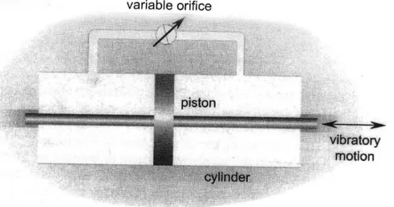
Mohd Asqalani Bin Naharudin, 2008 [6] explain about semi-active
suspension system. A semi-active suspension system utilizes a variable damper or
other variable dissipation component in the automotive suspension. An example of
a variable dissipater is a twin tube viscous damper in which the damping coefficient
[image:19.595.200.482.195.343.2]can be varied by changing the diameter of the orifice in a piston.
Figure 2.2.2 : Schematic of a variable damper [6]
Comparison between active and active suspension system shows
semi-active use less power than fully semi-active suspension system. The power consumption
in a semi-active system is only for purpose of changing the real time dissipative
force characteristics of the semi-active device. Semi-active systems cannot cause
the suspension system to become unstable unlike active systems [6]. However, in
this study suspension system used is active vehicle suspension system as the real
car move on the road is type of active suspension system.
7
F
=
k x
Meanwhile in active system, the component of spring or damper is replaced
with an actuator. An actuator is controlled by using the feedback from the vehicle
body. Technically, active suspension system is used to control the movement of a
vehicle using onboard controller by controlling the tire movement during cornering,
braking and accelerating. The method of the controller for active suspension can be
divided into four types based upon the control techniques namely Solenoid
Actuated, Hydraulic Actuated, Electromagnetic Recuperative and
Magneto-rheological Damper.
Saban Cetin, and Ozgur Demir, 2008 [5] state that the model of active
suspension system consists of a body and a wheel which are connected with a
suspension system. The suspension system is consisted of spring, damper, nonlinear
elements. An actuator is also connected between the car body and the wheel while
the wheel spring is in contact with the road profile. If road that widely used is flat
and do not have any disturbance, then suspension would not be necessary.
A car suspension is comprises with several of components and provides all
the solution for car stabilization. Tan Wei Teck, 2001 [1] explain in his thesis about
spring element in car suspension. The springs play an important part in handling of
the suspension system. Springing action should be as soft as possible for the best
ride comfort. Road shocks should be swallowed and not transmitted to the vehicle.
Springing action should also be progressive, taking a bump in the roadway softly at
first and gradually hardening towards the end of the deflection. Springing action
should assure evenness of ride regardless of vehicle load.
8
[image:21.595.226.450.582.714.2]
Figure 2.2.4 : Spring system [1]
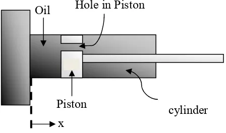
Second thing play an important part in the suspension system is damper.
Function of damper or shock absorbers are required to help the metallic spring to
control the spring action. Tan Wei Teck, 2002 [1] state generally, the spring is the
element that cushions the shock and therefore needed a shock absorber as a brake
on the spring to keep it from continuing its spring action. In a typical damper, the
comparison resistance is considerably lower than the rebound resistance.
The shock absorber is to control movement of vehicle against initial forces.
The force F is required to expand the damper with velocity V:
F = Dv (2.2)
(2.3)
Where D is constant known as the damping coefficient and unit SI is Newton
Second/Meter (Ns/m-1)
Figure 2.2.5 : The simple damper construction [1] Piston
x
f
dx
F
D
d t
=
Oil Hole in Piston
x
9
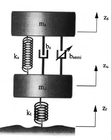
2.3 Quarter Car Model
Car model for this study used is Quarter Car model. A
two-degree-of-freedom (DOF) Quarter Car Model automotive suspension system is shown in
Figure 2.7. Mohd Asqalani Bin Naharudin, 2008 [6] explain the Quarter Car Model
represents the automotive system at each wheel i.e. the motion of the axle and of
the vehicle body at any one of the four wheels of the vehicle. The suspension itself
is shown to consist of a spring ks, a damper bs and a variable damper bsemi. The
variable damper bsemi can be set to zero in a passive suspension. The sprung mass
ms represent the quarter-car equivalent of the vehicle body mass. The unsprung
mass mu represents the equivalent mass due to the axle and tire. The vertical
stiffness of the tire is represented by the spring kt. the variables Zs, Zu and Zr
represent the vertical displacements from static equilibrium of the sprung mass,
unsprung mass and the road respectively.
[image:22.595.209.440.405.698.2]10
2.4 Controller used for Active-Suspension System
2.4.1 Fuzzy PID Controller
Saban Cetin, and Ozgur Demir, 2008 [5] has been done research for
nonlinear Quarter Car Model. In the control literature, there are several types of
control systems which use Fuzzy Logic as an essential system component. In this
study direct action type fuzzy logic controller applied to the 2-DOF nonlinear car
model. The direct action fuzzy PID controller is placed within the feedback control
loop and manages the PID options through fuzzy algorithm.
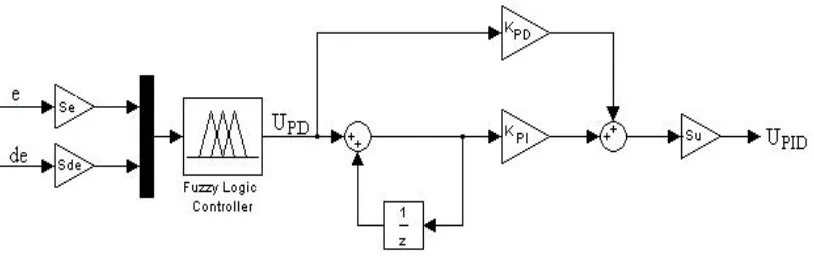
Conventional PID controller is the most widely used in industrial because of
its simple structure. However, main problem of PID is for the fix gains do not
produce reasonable performance over a wide range of operating conditions and
systems (time-delayed systems, nonlinear systems, etc). Fuzzy PID controller used
[image:23.595.127.534.445.577.2]in this paper is based on two input FLC structure with couple rules.
Figure 2.4.1 : Block diagram of the two input Fuzzy PID Controller [5]
The linguistic labels used to describe the Fuzzy sets were ‘Negative Big’
(NB), ‘Negative Medium’ (NM), ‘Negative Small’ (NS), ‘Zero’ (ZE), ‘Positive
Small’ (PS), ‘Positive Medium’ (PM) and ‘Positive Big’ (PB). Therefore a total of
11
2.4.2 Indirect adaptive interval type-2 Fuzzy Neural Network (FNN)
controller
Tsung Chih Lin, Mehdi Roopaei and Ming-Che Chen, 2010 [8] state FNN
controller is defined as an FNN logic system equipped with an adaptation
algorithm. Moreover, FNN is constructed from a collect of fuzzy IF-THEN rules
using fuzzy logic principles and the adaptation algorithm adjusts the free
parameters of the FNN based on the numerical experiment data. Like the
conventional adaptive control, the adaptive FNN control has direct and indirect
FNN adaptive control categories.
Figure 2.4.2 : The structure of type-2 Fuzzy Logic System [8]
There are five main parts in a type-2 FLS: fuzzifier, rule base, inference
engine, reducer and defuzzifier. After defuzzification, fuzzy inference,
type-reduction and defuzzification, a crisp output can be obtained. By using FNN also
![Figure 2.1 : A quarter car representation of passive B [4]](https://thumb-us.123doks.com/thumbv2/123dok_us/103202.9635/18.595.224.382.386.585/figure-quarter-car-representation-of-passive-b.webp)