Rochester Institute of Technology
RIT Scholar Works
Theses
Thesis/Dissertation Collections
2-1-2007
A reverse engineering process for mechanical
engineering systems
Frank Tamarez-Gomez
Follow this and additional works at:
http://scholarworks.rit.edu/theses
This Thesis is brought to you for free and open access by the Thesis/Dissertation Collections at RIT Scholar Works. It has been accepted for inclusion in Theses by an authorized administrator of RIT Scholar Works. For more information, please [email protected].
Recommended Citation
A REVERSE ENGINEERING PROCESS FOR
. MECHANICAL ENGINEERING SYSTEMS
By
Approved by:
Frank B. Tamarez G.
A Thesis Submitted
m
Partial Fulfillment
of the
Requirements for the
MASTER OF SCIENCE
In
MECHANICAL ENGINEERING
Edward Hensel, Ph.D.
Department of Mechanical Engineering
(Thesis Advisor)
Alan Nye, Ph.D.
Department of Mechanical Engineering
(Department Representative)
Elizabeth DeBartolo, Ph.D.
Department of Mechanical Engineering
Marcos Esterman, Ph.D.
Department of Industrial
&
System Engineering
George Slack, MS
Department of Electrical Engineering
Department of Mechanical Engineering
Kate Gleason College of Engineering
Thesis/Dissertation Author Permission Statement
() cess
I understand that I must submit a print copy of my thesis or dissertation to the RIT Archives, per current RIT guidelines for the completion of my degree. I hereby grant to the Rochester Institute of Technology and its agents the non-exclusive license to archive and make accessible my thesis or dissertation in whole or in part in all forms of media in perpetuity. I retain all other ownership rights to the copyright of the thesis or dissertation. I also retain the right to use in future works (such as articles or books) all or part of this thesis or dissertation.
Print Reproduction Permission Granted:
I,
PI"
WK
xlJ1A1
(f(eR-t'
,
hereby grant permission to the Rochester InstituteTechnology to reproduce my print thesis or dissertation in whole or in part. Any reproduction will not be for commercial use or profit.
Signature of Author: _ _ _ _ _ _ _ _ _ _ _ _ _ _ _ Date:
(1
1M( A1!
o-f
Print Reproduction Permission Denied:
I, , hereby deny permission to the RIT Library of the Rochester Institute of Technology to reproduce my print thesis or dissertation in whole or in part.
Signature of Author: _ _ _ _ _ _ _ _ _ _ _ _ _ _ _ _ _ _ Date: _ _ _ _ _
Inclusion in the RIT Digital Media Library Electronic Thesis
&Dissertation (ETD) Archive
I, , additionally grant to the Rochester Institute of Technology Digital Media Library (RIT DML) the non-exclusive license to archive and provide electronic access to my thesis or dissertation in whole or in part in all forms of media in perpetuity.
I understand that my work, in addition to its bibliographic record and abstract, will be available to the world-wide community of scholars and researchers through the RIT DML. I retain all other ownership rights to the copyright of the thesis or dissertation. I also retain the right to use in future works (such as articles or books) all or part of this thesis or dissertation. I am aware that the Rochester Institute of Technology does not require registration of copyright for ETDs.
Acknowledgments
I wouldliketoexpressmyextreme gratitudetoallthepersons whoassistedme
withthe thesisand providethenecessarysupportfor itscompletion: Dr. EdwardHensel,
mythesis advisor, forbeingvery patient, encouraging,understanding, supporting and a
friend fortheguidance ofinthewritingofthis thesisinthepasttwo years. Hehasbeen
likeafatherindifficultand smoothtimes,withoutthehelpofDr. Hensel,I maynever
have completedthe thesis. Dr. ElizabethDeBartolo,Dr. Marcos Esterman Dr. Alan Nye
andMS. George Slackforprovidingprofessional andpersonalguidancethatgreatly
enhanced and preparedmymindandabilitytofocusonthis thesis and assistancetohelp
minimizethestressoflearningnewthings. Furthermore, Iwouldliketo expressmy
deepestgratitudetomygirlfriend, LoriRosario, for herlove,patience,understandingand
supportthatalways wastherewhen needed. Iexpress anoverwhelmingappreciationto
myparents,Francisco andAna, foralwaysbeingtherewhenIneeded supportand your
numerous sacrificesextended farbeyondthedutiesofparents,aswellas friends, and I
loveandthankyou. Finally,I wouldliketo thankGodforbeingbesidemeallthe times
Table ofContent
ACKNOWLEDGMENTS 1
TABLEOF CONTENT 2
LISTOFFIGURES 9
LISTOFTABLES 17
ABSTRACT 19
CHAPTER 2 LITERATURE REVIEW 31
2.1 ApplicationofReverse Engineering MethodsinBusiness 32
2.2 ApplicationofReverseEngineering MethodsinSoftware 36
2.3 ApplicationofReverse Engineering MethodsinMechanicalComponents 48
2.4 ApplicationofReverse EngineeringMethodsforMechatronics 53
2.5 ApplicationofReverseEngineering MethodsinIndustrial Engineeringand
Miscellaneous 57
2.5Literature ReviewSummary 66
CHAPTER 3.0REVERSE ENGINEERING PROCESS FOR MECHANICAL ENGINEERING
SYSTEMS(REPMES,) 67
3.1 ManagementDecision,selecta product forREand definegoals 71
3.2CompetitiveBenchmarking 71
3.3 Needassessment 72
3.4Establishing Engineering Specifications 74
3.5 SelectProductstoRE 76
3.6Replace Lost Technical Data Package 78
3.7Knowledge Expansion 79
3.9 GettingtheProduct(s)forRE 82
3.10GettingProductDocumentation 83
3.11 Design Team SelectionandREplan 84
3. 12 Product Functionality 86
3.13Visualinspection oftheproduct and understandhow itoperates 87
3.14DesignFeature 90
3.15ElectricalFeature 91
3. 16Mechanical Feature 92
3.17TechnicalImplementation 93
3.18Critical Analysis 95
3.19 Validation 96
3.20 Designverification 98
3.21 ProcessStateEstimation"Inconsistency"
99
CHAPTER4CASE STUDY:REPMES,APPLIED TO A FLASHLIGHT 100
4.1 ManagementDecision 101
4.2Competitive BenchmarkingandProduct Improvement 102
4.2.1Needassessment 102
4.2.2EstablishEngineeringSpecifications 103
4.2.3SelectnProductsforReverseEngineering 103
4.3ReverseEngineering Sub-Objectives 104
4.4AcquiretheProduct(s)forReverse Engineering 104
4.5Get Product Documentation 105
4.6Design TeamSelection 106
4.7Product Functionality 106
4.8Visualinspectionofthe product and understand how it operates 107 4.8.1Inspection,Dissection, andBill ofMaterials 707
4.11 Mechanical Features 112
4.12 MaterialProperties 112
4. 13 Critical Analysis 112
4.13.1AssemblyAnalysis 112
4.13.2 MechanicalAnalysis 113
4.13.3 Material PropertiesAnalysis 114
4.14 Technical Data Packagefor theV2D-B Flashlight 116
4.15 Case Study Summary 118
CHAPTER5 REVISIONSOFREPMES,TO IMPLEMENTREPMES2 119
CompetitiveBenchmarking 119
ReplaceLost Technical DataPackage(TDP)andKnowledge Expansion 120
TechnicalDataPackage 125
CHAPTER 6IMPLEMENTED REVERSE ENGINEERING PROCESS FOR MECHANICAL
ENGINEERINGSYSTEM(REPMES2)TO TORQUE CONVERTER"FORD"
128
6.0ManagementDecision,selecta product forREand definegoals 129
6.1 ProductSelectionbasedoneconomic factors 130
6.2 AcquiretheProduct(s)forReverse Engineering 134
6.3 Design Team Selection 134
6.4 Reverse Engineering Plan 135
6.5 GetProduct Documentation 136
6.6Product Functionality 136
6.7 Dissecttheproductandunderstand how it operates 137
6.7.1Inspection 137
6.8Designfeature 139
6.9Technical Implementation (Designfeature) 140
6. 10 Criticalanalysisoftorqueconverter(DesignFeature) 141
6.11 ElectricalFeature 144
6. 12MechanicalFeature 144
6. 13 Critical Analysis (MechanicalFeature) 145
6.14 MaterialProperties 146
6. 15 Criticalanalysis(MaterialProperty) 147
6.16 Technical Data PackagefortheTorque Converter"Ford"
149
6. 17Case Study Summary 152
CHAPTER 7 REVISIONSOFREPMES2TO FINAL REPMES 153
CHAPTER 8 CONCLUSION 156
CHAPTER 9 RECOMMENDATION FORFUTUREDEVELOPMENTS 157
REFERENCES 158
APPENDKA: EXPLANATION TOOLS 164
A.l Stepsfor thecreation ofthe"HouseofQuality" 164
A.2 DeterminingtheRoot Cause: 5 Whys 168
A.3 FASTMethod 170
A.4 Howtocreatea precedent result diagram"IshikawaDiagram"
171
APPENDKB: REVERSE ENGINEERINGREPORT AND TECHNICAL DATA PACKAGE
FOR THE RAYOVAC FLASHLIGHT V2D-B 173
B.i Title Page 175
B.n ExecutiveSummary 176
B.m Reverse Engineering ObjectivesandStatementofWork 177
B.I Introduction 177
B.2 Product DissectionandInspection Report 177
a. Product inspection 177
b. GatheringBasic Information 178
d. Photographic BillofMaterials 779
e. AssignmentofNamesandNumberstoPartsandSubassemblies 184
B.4. Design Analysis 189
a. UserNeedsAssessment. 189
b. CompetitiveBenchmarking 207
B.5 Mechanicalfeaturesanalysis 203
B.6. Electrical FeaturesAnalysis 204
a. Schematicdiagrams. 204
b. Circuitsimulations 205
c. Component Specification 205
B.7 MaterialpropertiesFeaturesAnalysis 206
B.8 System FunctionalityAnalysis 206
a. SetMode 206
b. Identifyingtheroot causeusingtheFive Whys 207
c. FAST Diagram MethodfortheFlashlight V2D-B 208
d. Function TreefortheFlashlightV2D-B "Rayovac"
210
e. Black Box oftheFlashlight V2D-B 277
B.9 Final Technical Data Packagefor theDevice 213
a. 3-D Solid ModeloftheDevice 275
b. 2-DDrawingPackage 27<5
B.ll. Extrainformation 229
APPENDK C REVERSE ENGINEERING REPORT AND TECHNICAL DATA PACKAGE
FOR THE FORD TORQUE CONVERTER 239
C.i Title Page 241
C.n Executive Summary 242
Cm Reverse Engineering ObjectivesandStatementofWork 243
C.3. ProductDissectionandInspection Report 247
a. Productinspection
..247
b. GatheringBasicinformation ..249
c. Mass oftorqueconvertercomponents ..249
d. PhotographicBill ofMaterials 250
C.4. Torque Converter Functionality 254
a. Eventprocess chaindiagram 254
b. Identifyingtheroot causeusingtheFive Whys 255
d. FunctiontreefortheTorqueConverter 260
e. BlackBoxanalysisfortheTorque Converter. 261
C.5. Design FeaturesAnalysis 263
a. Mathematicalmodeling oftheTorque ConverterandFluidCoupling. 263
b. Analyzingthe torqueconverterintermsoffluidand clutchfriction 277
c. Criticalanalisysdesignfeatures 273
C.6. MechanicalFeaturesAnalysis 280
a. Operations 280
b. Multiplication 283
C.7. Electrical FeaturesAnalysis 285
C.8. MaterialsProperties Features Analysis 285
a. RockwellHardness 285
b. Brinell Hardness 287
c. Metallography 290
d. ResearchandComparisons 293
e. Analysisofvolumefractionbyimage 298
f Criticalanalysisfor narrowing downoptions 300
C.9. Final Technical Data Packagefor theDevice 304
a. 3-D Solid Modelofthedevicecreatedusing Pro-E Wildfire2.0 304
CIO. Extrainformation 324
a. GraphofCruisingspeed. 324
b. FluidCoupling 325
APPENDK D: FINAL REVERSEENGINEERING PROCESSFOR MECHANICAL
List ofFigures
Figure 1Engineeringstudents learn through studying examples ofdesigned systems 21
Figure2Reverseengineering requires testing and investigation of productsunder
investigation.Cartoontaken from 22
Figure 3 Drawingofa"lowerreceivingtube"
takenfrom aTechnicalData Package [7].23
Figure 4 Lexus
-phototakenfromcontent source 26
Figure 5Apollo Rocketfrom the1960'sleaving theNASAheadquarters 27
Figure 6 SolenoidValvesmanufactured by theG.W.Lisk Companyfor applications such
asvehicle, aerospace, marine,etc 28
Figure 7 Formanalysis andProcess ModelGeneration,inspired byKim 33
Figure8 Event ProcessChainDiagramfromKim 34
Figure 9 REas a tool for productplanning,inspired bySchumacher 36
Figure 10 Processcontrolsteps forRE,inspired byHildreth 38
Figure 11 ExampleofProcesscontrol stepforRE,whereLSLandULSare the limits set
TO BE INCONTROL 40
Figure12REprocess and documentation for softwaresystem,inspired byAbbattista....41
Figure 13 REprocess by applying object-oriented frame working to understand the
CONCEPT OFTHEDOMAIN,INSPIRED BYJ-M DeBAUD 43
Figure14 Synchronizedrefinementsin order to implementdesign,inspired byJ-M DeBaud
43
Figure 15 CharacterizingandevaluatingREprocesscomponents,inspired byTortorella
Figure16 REMethodologytoreconstruct data flowdiagrams,inspired byBenedusi 46
Figure17REstepstoanalyzedata forsoftware,inspired byMuller 47
Figure 20Reverseengineering of mechanicalcomponentsforCAM /CAD,inspiredby
Kalra 49
Figure21 REtogenerate a solid model usingCAD,inspiredby byGirishPhansalkarand
Rajesh N.Dave 51
Figure 22 Reverseengineeringand re-engineering of avionicslegacycomponents,
inspired byRiffle 55
Figure23Stepsfor reverse engineering as anapproachto studyingMechatronics,
INSPntED bySaleh 56
Figure24Preliminaryplan for reverse engineering techniques forRe-Plenishmentof a
Spares Breakoutprogram,inspdjedbyDiMascio 59
Figure25Reverse Engineeringand redesign accord toOtto 60
Figure26Investigation,prediction,and hypothesis tools forRE,takenfromOtto 61
Figure27 ConcreteExperience:Function & Form- tools for
RE,taken fromOtto 61
Figure28Fourprocessstages for reverse engineering byIngle 63
Figure29Fivesteps to productdevelopment,OttoandWood 65
Figure 30 Apyramid illustrating therelationshipsand flow ofinformationbetween
engineering, re-engineering,andreverse engineering 67
Figure 31 Preliminaryphases ofREPMES1aspresentedin the original thesis proposal...70
Figure 32 Laterphaseof REPMES1aspresentedinthe original thesis proposal 70
Figure 33 Need assessment, Kevin OttoandKristin Wood 73
Figure 34 EngineeringSpecifications,Kevin OttoandKristinWood 75
Figure37 GettingtheProduct(s)forRE 82
Figure38 Getting Product Documentation 83
Figure39 Design Team Selection 85
Figure 40 REplanlayout 86
Figure 41 ProductFunctionality,KevinOttoandKristinWood 87
Figure42 Visual inspections,KevinOttoandKristinWood 89
Figure43Design Features 90
Figure 44ElectricalFeature 92
Figure45 MechanicalFeature 93
Figure 46 TechnicalImplementation 94
Figure47 Critical Analysis 96
Figure 48Validation,Riffle 97
Figure 49 Designverification 98
Figure 50 ProcessStateEstimation 99
Figure 51 Rayovac Flashlight Model V2D-Bused inCase Study 101
Figure 52 Electronicallyregulated,variableoutputLEDflashlight 106
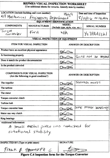
Figure 53Sampleinspection form to be used by the inspector during dissection.
Additionaldetablsarepresented in theAppendixB 109
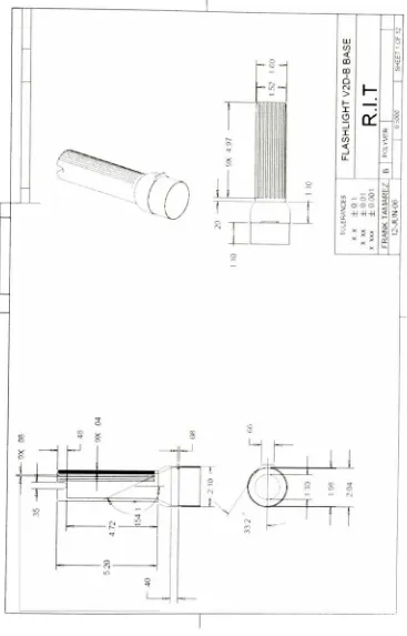
Figure54the2DdrawingoftheBaseoftheFlashlight V2D-B 110
Figure55ElectricalCmcurrof theFlashlight V2D-B "Rayovac Ill
Figure 56 Assemblyview of the solid modelflashlight 113
Figure 573Dmodelof theflashlight basecreated usingPro-Ewildfdie2.0 114
Figure59aREPMES2-Revised Process
123
Figure60FinalComplete Technical Data Package 127
Figure61 Sampleprojectselectionrecommendationsheetto be used by the design team
duringEconomicanalysis.Additionaldetails are presentedinAppendix C 131
Figure62ReturnonInvestment(ROI)equation,takenfrom[39] 132
Figure63 Exampleinspection form for theTorqueConverter 138
Figure 64 Pro-EdrawingofImpellercase 140
Figure65Vehicledisplayoflocation forTorqueConverter 141
Figure663DmodeloftheTorque Converter 142
Figure67 Actualpictureofthe torqueconverterImpellershowing the guide rings and
its fins 142
Figure68
-Mathematicalequationsofthree components of the torqueconverter 143
Figure 69Statorsthreecomponents 145
Figure 70 ExplodedviewoftheTorqueConverterthat shows all parts andcomponents
145
Figure 71 Fluidflows in the torqueconverter 146
Figure 72 DistanceversusHardnessGraphforTorque Converter'simpellercase 148
Figure73 PublishedgraphforDistanceversusHardnessGraph 149
Figure 74- REPMESmaterialProperty Process 154
Figure A.1 QFDRepresentation,inspiredbyKevin OttoandKristin Wood 165
Figure A.2 FASTMethod,iNSPntED byKevin OttoandKristinWood 171
Figure A.3 IshikawaDiagram,taken fromAnswers.com 172
Figure B.2 Ishikawa Diagramor"Assembly PrecedenceDiagram"
forFlashlight Model
V2D-B 181
Figure B.3 ExplodedviewforFlashlight V2D-Bwith correspondingfeatureandpart
numbers 184
Figure B.4 AnkurAbrollike/dislike survey 190
FigureB.5Lori Rosariolike/dislike survey 191
FigureB.6 Juan M.Garcialike/dislike survey 191
Figure B.7 Stephanie Pntolike/dislikesurvey 192
Figure B.8 LoriRosario Questionnairemethod 193
FigureB.9 Ankur AbrolQuestionnairemethod 194
Figure B.10Stephanie Pmo Questionnadxemethod 195
Figure B.ll Juan M.Garcia Questionnadiemethod 195
Figure B.12SchematicdiagramoftheFlashlight V2D-B 204
Figure B.13 FASTdiagram for theFlashlightV2D-B,inspired byKevinOttoandKristin
Wood[40] 210
Figure B.14Functiontree for theFlashlight V2D-B"Rayovac" 211
FigureB.15Black BoxfortheFlashlightV2D-B 212
Figure B.16 Black Boxfor theFlashlight V2D-B 212
Figure B.17 Refinedfunction structure for theFlashlightV2D-B 213
Figure B.18 Back ExplodedviewoftheFlashlight V2D-B"Rayovac" 214
Figure B.19 Complete Assembly-DefaultviewoftheFlashlight V2D-B
"Rayovac"
214
Figure B.20 Complete Assembly-Top ViewoftheFlashlightV2D-B
"Rayovac"
FigureB.21 Complete SecondaryAssembly-Default
view oftheFlashlight V2D-B
"Rayovac"
214
Figure B.22CompleteSecondaryAssembly-Default
sideviewoftheFlashlight V2D-B
"Rayovac"
215
FigureB.23 DissembledviewoftheFlashlightV2D-B "Rayovac 215
Figure B.24CompletetransparentviewoftheFlashlight V2D-B "Rayovac 215
FigureB.25 Flashlight V2D-B Base 217
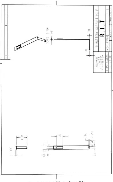
FigureB.26 Flashlight D BatterySupportPole 218
FigureB.27 Flashlight Water Protector Washer 219
Figure B.29 FlashlightCopperPole 221
Figure B.30 Flashlight Bulb Base 222
Figure B.31 Flashlight V2d-B Switch 223
Figure B.32 Flashlight Bulb "Mag 4Cell" 224
Figure B.33 Flashlight Lightcover 225
Figure B.34 Flashlight V2D-BSpring 226
FigureB.35 FlashlightConvexLens 227
FigureB.36 Flashlight Hand Band 228
Figure B.37 Component Formfor theFlashlight V2D-B 229
Figure B.38 Component Formfor theBulboftheFlashlight V2D-B 231
Figure B.39 Component Formfor theLightreflectorsof theFlashlight V2D-B 232
Figure B.40 Component Formfor theCurrentflow deviceof theFlashlightV2D-B 233
Figure B.41 Component Formfor thelightraypointerof theFlashlightV2D-B 234
Figure B.43 Component FormfortheSpkalspring andALpoleof theFlashlightV2D-B
236
FigureB.44Component Formfor the light cover of theFlashlightV2D-B 237
Figure B.45 ComponentFormfor the copper pole and switchof theFlashlight V2D-B ..238
FigureD.IaREPMESi-Revised Process
...329
FigureD.IBREPMES2-Revisedprocess continued
330
FigureD.2REPMES2-Complete Technical Data Package
331
FigureD.3Need assessment, Kevin OttoandKristinWood 332
FigureD.4EngineeringSpecifications,KevinOttoandKristin Wood 332
Figure D.5SelectnProductto reverse 333
FigureD.6Stepstoward product selection 334
Figure D.7REsub-objective(s) 335
FigureD.8GettingtheProduct(s)forRE 336
FigureD.9Getting Product Documentation 336
FigureD.10DesignTeamSelection 337
FigureD.ll Design TeamSelection 338
Figure D.12 ProductFunctionality,Kevin OttoandKristin Wood 339
Figured.13 Visualinspections,KevinOttoandKristinWood 340
Figured.14 Design Features 341
FigureD.15 ElectricalFeature 342
Figure D.16 Mechanical Feature 342
Figure D.17 Technical Implementation 343
Figured.19Valdjation,inspiredbyRiffle 345
Figure D.10 Designverification 346
Figure D.21 ProcessState Estimation 346
ListofTables
Table 4.1REPMESiCaseStudy Task Breakdownlocation 100
Table4. 2Design TeamCore Membership EngineeringFunctionsfor theFlashlight V2D-B
106
Table4. 3ElectricalfeatureFlashlight V2D-Bat1 Meter Ill
Table 6.01.Reverseengineeringplanschedule andlocation 129
Table B.IMassofPartsin theProduct 179
Table B.2 Photographic BnxofMaterialof theFlashlight V2D-B 182
Table B.3 Summationimportance of the questionnaire method 196
Table B.4 Priorityofcustomer needs 198
Table B.5 Priorityofdesign level 199
Table B.6 Priorityofergonomics 200
TableB.7 Competitive Companiesanddescriptions 201
Table B.8 Competitiveproductanddescription 202
Table B.9-Quality FunctionDeployment(QFD)/ HouseofQuality Matrk 203
Table B.10 ElectricalfeatureFlashlight V2D-Bat1 Meter 205
Table B.ll SchematicsforFlashlightV2D-BONorOFFmode 207
Table CI Individualpartsweight 249
Table C.2 Torqueconverter total weight 249
Table C.3 BillofMaterialsfor theTorqueConverter"Impeller
Assembly"
252
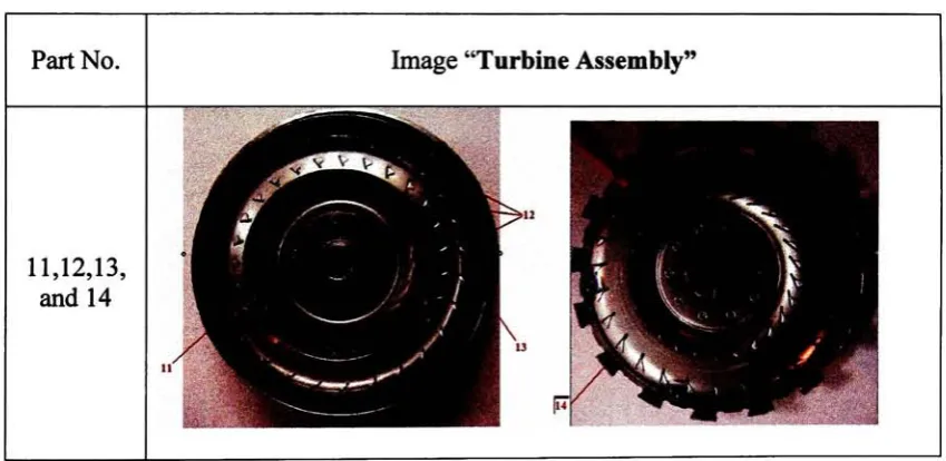
Table C.4 Billof Materialsfor theTorque Converter "Turbine
Assembly"
252
TableC.5Billof Materialsfor theTorqueConverter "Stator
assembly"
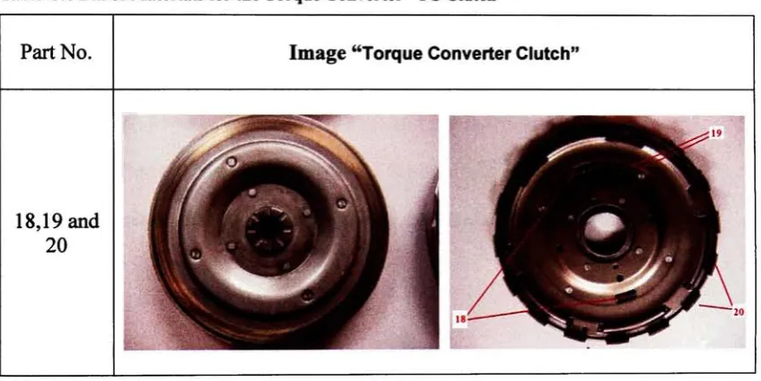
Table C.6BillofMaterialsfor theTorque Converter"TCClutch"
253
TableC.7 BillofMaterialsfor theTorqueConverter"TCBase"
254
TableC.8Rockwell Hardnessvalues for theimpellerand the turbine 287
TableC.9- BrinellHardnesstestresults 290
Table CIO- Chemicalcomposition ofAlloysteel
andcarbonsteel,taken from[54] 302
Abstract
Thisthesispresents aliteraturereviewofcurrent reverse
engineeringtechnologies
andprocesses,with an emphasis ontoolscommonlyusedin SoftwareReverse
Engineering(SRE). Usingthe foundationoftheliteraturereview, the thesiswillthen
propose a standardprocess,referredtoas "AReverseEngineeringProcessfor
MechanicalEngineeringSystems(REPMES)."
The REPMEStoolis intendedtoenable
engineerstounderstandhowcurrent products work. Additionally, REPMES mayallow
engineeringdesignteams tomoreeffectivelyrevisetheirproductdesignsthrough
competitivebenchmarking. The REPMES is illustratedthroughapplicationtocase
studies of a consumerflashlightandan automotivetorqueconverter.
UnlikethefieldofSoftware ReverseEngineering(SRE),thereisnotcurrentlya
published standardized procedureto successfullyimplementreverse engineeringof
mechanicalengineeringsystems. The REPMESprocessintroduced here differs from
SREinthat the targetforSREistounderstandtheinnerworkingsofacomputerprogram
or system. However,REPMEShastoaccountforthematerialsused, thelimitationsof
thesamematerials, thephysical conditionsunderwhichthesystem mustoperate, the
meantimebetweenfailure,manufacturingprocesses andtolerances, and avarietyof
otherfactorsnottypicallyencounteredinsoftware systems.
FollowingtheintroductionandillustrationofREPMES usingtheflashlightcase
study, theREPMEStoolwillbeappliedto theanalysis ofatraditionalmechanical
device, atorque converter, to evaluatetherobustness oftheREPMESinthecontext of a
typical application. Useofthe REPMESwillbedemonstratedtoprovide athorough
structurewillbeemployedtoprovide alistofrecommendedimprovementsto the
Chapter 1 Introduction
Reverse engineeringhas several
definitions,
and attimescanbeeasilyconfusedwiththedefinitions ofengineeringandre-engineering.Eachofthese termshas distinct
meaningwithinthecontext ofthis thesis.
"Engineering
istheapplicationofscientificandtechnicalknowledgeto solvehumanproblems. Engineersuse imagination,judgment
andreasoningto applyscience, technology, mathematics,and practical experience.The
result isthedesign, production, and operation of useful objects orprocesses."
[1] Figure
1 shows agroupofearly 20th century engineeringstudentsfromtheUS Military
AcademyatWest Point analyzingabridgestructuretoenhancetheirunderstanding. It is
common practicefor engineeringstudents, andpracticingengineers, tolearn fromprior
examples ofbothgood andbad designsolutionsto a particular problem.
/
i
mSM
Figure1Engineeringstudentslearnthroughstudyingexamples ofdesignedsystems[2].
"Re-engineeringistheprocess ofexamination, understandingand alteration of a
system withtheintentofimplementingthesystemina new
form"
distinction betweenre-engineeringandengineering,forthepurposes ofthisthesis, isthe
processofiteration. Withinthisthesis,engineeringrefersto thefirstrendition,orinitial
release,of a product design,whilere-engineeringrefersto adesignvariationbasedupon
performance analysis oftheprecedinggeneration.
However, "ReverseEngineering (RE) istheprocessofdiscoveringthe
technologicalprinciples of a mechanical applicationthroughanalysisofitsstructure,
functionand operation.Thatinvolvessometimestakingsomething (amechanicaldevice,
anelectricalcomponent,a softwareprogram, etc.)apart andanalyzingitsworkingsin
detail."
[4] Inotherwords,reverseengineeringhelpustounderstandhowa component
functions. Figure 2illustrates ahumorousbutsometimes accuratedemonstrationofhow
testinga product canhelpan engineerbetterunderstandthefunctionsand propertiesofa
product.
DITH WHAT'S THIS RESETBOTTONFOR ?"
"A Technical Data Package(TDP) isatechnicaldescriptionof anitemadequate
forsupportinganacquisitionstrategy, production, engineering, andlogisticssupport.
The descriptiondefinestherequireddesignconfiguration and procedures requiredto
ensureadequacyofitemperformance. It consists ofallapplicabletechnicaldatasuchas
drawingsandassociatedlists, specifications, standards,performancerequirements,
qualityassuranceprovisions, andpackagingdetails. " [6] Thetechnicaldatapackage
essentiallycontains allinformationrequiredtomanufacture a product.Figure 3shows a
drawing, acriticalelementofaTDP,ofalowerreceivingtubefrom
Savit Corporation.
(fcl8M!" "*'""""
'
IIII* ie*H illIt RUM 6MM St
r,f!p-MT!.'!! -Si
to*MtrUfltH ft HWH IMIMU V*
KM utiviitn
Iruwm..t-uUUlboM.fr* m.i
nMB **"[it)*" **' a*'f'* >c-' ** -i*
rUHH WLjJ.lt<,ltl-.ti*'MU
Tsste*=f_
Figure3Drawingof a"lower receiving
tube"
takenfromaTechnicalData Package [7].
ATechnicalData Packageismadeupofmanyelements. Onegeneral
specificationforTDPisdescribedbythe militaryspecificationMIL-DTL-31000C,which
requirementsfor preparingatechnicaldatapackage(TDP)composedofone or more
TDPelements and related TDPmanagementdata products."[8]
The militaryspecificationMIL-DTL-31000C [8]definesthelist ofitemstobe included
intheTDPas follows:
Engineeringdrawings
Associated lists
Specificationsthatdefine
Function,performance, interfaces
Physical geometry,other constraints
Processdescriptions
Materialcomposition
Safetyrequirements
Preservationandpackagingrequirements
Testrequirementsdataandqualityprovisions
Preventativemaintenance system/MaintenanceRequirements
Coordination, interchangeability, formfit, andfunction information
Three primarymotivations foran engineerto perform reverseengineeringinclude
(1) expansionofknowledgeandunderstanding,(2)competitivebenchmarking,and(3)
replacement of alostorincompletetechnicaldatapackage.
Competitivebenchmarkingispracticedbymost modemengineeringandproduct
developmentorganizations inaneffortto continuallyimprovetheirproducts anddesigns.
Theancient ChinesewarriorSun Tzutaughthismento "knowyourenemy"
beforegoing
into battle. Forif"youknowyourenemyandknowyourself,"
feartheresult of ahundredbattles." But, SunTzu warned, "Ifyouknowyourselfbutnot
the enemy, forevery victorygained you will also suffer adefeat." [9]
Identifyingtheproduct, service and process fromtopcompetitorsandcomparing
it with your ownisthe
key
toremain competitiveinthemarket. Benchmarkingdoesnotonlyillustratethefeaturesof another company's productsbutalsotheengineeringand
customer's satisfaction oftheproductbysurveys conducted and exploredbythatspecific
company.
Oneexampleofa modern corporationthatconducts competitivebenchmarkingis
General Motors(GM). AsofOctober2006,"GM isthelargestautomobilemakerinthe
world"
[10],sellingmillions of cars per year. Whattoolsdo corporationsemploytolearn
thedesiresofthecustomersintheirmarket?Howdolargecompaniesunderstandthe
engineeringdesignsof productsfromothercompanies?Howcan manufacturers reduce
thecosts associated with productionfromoneyearto thenext?Reverse engineeringand
benchmarkingare essentialtoolsusedin answeringeach ofthesequestions.
General MotorsCorporation, likemanyother majormanufacturers, hasaformal
programforbenchmarkingproduct madebycompetitors.GMoperatestheVehicle
Assessment andBenchmarkingActivity(VABA),andpreparesinternalreportsfor
dozensof vehicles annually. Forexample, intheinterval betweenJanuary
-May 2006,
GMpurchased a$49,000 Silver Lexus RX 400h hybridsportutilityvehicle(SUV),
Figure 4 Lexus- phototakenfrom
content source[11]
The Lexus SUV, manufacturedbyToyota,ishighlyregardedas ahighend
vehicleinthe SUVmarket. GMdisassembledtheirLexus SUVattheirGM Technical
Center located inWarren, Michiganinan efforttounderstandeveryaspectofthe vehicle,
ranging fromthepartsused, to estimatingtheproduction cost. It isreportedinthe
literature [12]theGMconductsteardownsontheirown vehicles aswellasthevehicles
oftheircompetitors suchasBMW, Mercedes, Hondas, Lexus, Toyota,Chryslers, and
Ford. Itisestimatedthatabouttwentyvehicles aresubjectto theprocessknownas a
"fulltrim-sawcut"
whichistheprocess ofcuttingdoors,roofpillars andfenders in
100-mm-wide crosssections,whicharethenscanned intodigitalblueprints foranalysisby
engineers. Results for 2007includeChevyMalibu Hybrid(2007)which willhave 822
propulsion parts compared withthe 1,432partsthatmakeuptheToyota Prius. [12]
Isthereanyreasonthatacompanyusesreverseengineeringonitsown product(s)?
Isthatpossible? Whywould acompanyundergothatprocedureinternally? Engineers
use reverseengineeringto theirown productsasatoolwhentechnicaldataaremissing
andtoverifydesignintentoftheirengineeringstaffthroughindependentvalidation. One
waytorecovermissingtechnicaldataiswiththehelpof reverse engineering. Agood
missionsbyNASA
during
the 1960's. In 1969, manfirststepped onthe moon, the
Apollorocket usedisshowninFigure5. Ifwe wanttoaccomplishthis taskagain, whatis
thefastestwayitcouldbeaccomplished?
First, takinginto accountthatatthe timewe
traveled to the moon, theoriginaltechnicaldata,andtheTechnical DataPackage(TDP)
was not created on computersbecausetheIntel 1103 ComputerMemory(Theworld's
firstavailabledynamicRAM chip)andIntel 4004Computer Microprocessor (The first
microprocessor)were availablein 1970and 1971 respectively
-well afterthedesign
phase ofthe 1960'swhentherelevant engineering drawingsand analyses were compiled.
131
mm
l-M-WII
59 M
/ 1
11
1 '
'
^1
**- :. \
Figure 5 Apollo Rocketfromthe1960'sleavingtheNASA headquarters [13].
Second,atthecurrentdateof2006, it isexpectedthatmanyoftheoriginaldesign
engineers'
teammaybe deceasedor atleastretiredfrompractice. Third, changes in
designspecifications, drawingpractices, andtechnologiesforreproductionhaveevolved
dramatically
overthefivedecadelong historyof spaceflight. Therefore,itmaywellbethecasethat thebestwaytobegindesigninganewlunarmission vehicle wouldbeto
reverseengineeringtobetterunderstandhowtheyfunctionandthencomparethe
knowledge withthetechnologywehaveavailabletoday.
Engineerscan use reverseengineeringtoimprovethemselvestobecome better
engineers, by
learning
bestpractices fromthedesignof another engineer. For example,attheRochester Instituteof
Technology
inthesummer of2006,Professor Landschoot
used reverseengineeringwith students enrolledinthecornerstonedesignclassto
understandhowa solenoidvalve,similartothoseillustratedin Figure6, functionsand
what fabricationprocess were used intheirmanufacture.
"'j J'.y\fc
Figure6 SolenoidValvesmanufacturedbytheG.W. LiskCompanyforapplications such asvehicle,
aerospace, marine,etc.[14]
InordertounderstandthefabricationprocessProfessor Landschootwas required
togoto theGW LiskCompany,sincetheyweretheactualcreatorsofthesolenoid valve.
Thesolenoid valvethatProfessor Landschootisexperimentingwithisusedto teachhis
studentsinthe CornerstoneDesignclass. Thereverseengineeringprocessesthat
Professor Landschoot isusing to teachtheCornerstone Designstudents include:
functionaland economicanalysis, analysis ofits structure,functionandoperation,
disassembly
procedures and engineering drawings.Thisthesiswill focusondevelopmentofanew standardprocesstoimplement
referredto asReverseEngineering Processes in Mechanical
EngineeringSystems
(REPMES). Thebaselineversion ofREPMESwillbe basedupon aninvestigationof
relevantliterature fromthesoftware reverseengineeringand mechanical and electrical
designfields. Agraphical representationofeach reverseengineeringmethoddiscussed in
theliteraturewillbecreated, to summarize andillustrateavarietyof reverseengineering
processes. Commonelements willbe inferred fromtheliteraturereviewinvestigation,
resulting inthepreliminaryversion ofREPMES. The priliminaryversionofREPMES,
REPMESi,willbeappliedto a simple product- theRayovacflashlightV2D-B. This
flashlightwas chosenbecauseitpossessesdetailedcomponentsallwithin a simple
structure. Moreover,sinceits inventionin 1898, theflashlight hasundergone various
changes anddevelopments, specifically intermsofthetechnology,thematerial used as
well astherelationshipbetweenhumansandtechnological systems- ergonomics.
Using
knowledgegainedthroughanalysis ofthe flashlight, REPMES2willbe developedas a
directresult ofthe analysis oftheflashlight, REPMES2willbeadirectresultofthesteps
unforeseeninthedevelopmentofREPMESi. Oncereverseengineeringoftheflashlight
iscomplete, REPMES2willinevitablyneedtobemodifiedinordertoaccount for its
applicationtoareal-worldproduct. It isimportanttonotethatREPMES2mustbe
generic enoughforanyproduct'sanalysis,yetdetailedenoughtobeatruly
implementableprocess. This improvedversion willtakeintoaccount specifictools,
technologies andtheories thatwillapplyto theproduct.
Followingthedevelopmentoftherevisedversion,REPMES2willbeusedto
conduct a reverseengineering analysis ofatorque converter, afluid-couplingdeviceused
Thetorqueconverterisan appropriateexamplefortestingtheREPMES,because it isa
fullymechanicalcomponent;havingmechanical anddesign featureswith unique
manufacturingconsiderations, and materialpropertyconstraints.Justas withthe
flashlight,the torqueconverter willbecarefullydisassembledto thelastremovable
component(non-destructively) andtheneach ofthesecomponentswillbestudiedin detail usingtheREPMES2procedure.Thedevelopmentof a comprehensivetechnical
datapackageincludesa3-D solid model anddrawingpackage withfullydetaileddesign
and mechanical features, and material propertiesbasedonthecoordinates obtained from
aCMM(Coordinate-MeasuringMachine). Uponcompletionofthe torqueconverter case
study, afinalversion ofREPMES(REPMESFinai)willbeproposedforuse with a wide
varietyofmechanical products. The resulting REPMESwillbeatoolusefulfor
engineerswishingto expandtheirknowledgeof productdesign, conduct competitive
benchmarkingof abaselineproduct against competitiveproducts,and for replacing lost
Chapter2 Literature Review
BeforeintroducingtheReverse
Engineering
ProcessforMechanicalEngineeringSystems, one mustfirst become familiarwiththevarious resourcesofreverse
engineeringprocesses. Thischapter will provide anoverview ofreverseengineering
processesbeingapplied inbusiness, software, mechanical,mechatronics, industrialand
otherfieldsof applications. Detailed informationonhowreverseengineeringisapplied
tobothtangibleitems(suchasproducts)andnon-tangibleitems (suchas processesand
software)arediscussed
Thoughreverseengineeringcanbehighlybeneficial,it can alsobeusedinmore
antagonisticterms. Reverse engineering may beusedfora widevarietyofapplications.
Forexample, the paper, "Data Rights Provisions Do Not Protect Your Products inDoing
BusinesswiththeGovernment Be Alertto theNeedtoProtect YourselfandYour
Products Against 'ReverseEngineering'"byJacobB. Pankowski [15],isaboutarecent
lawsuitcasestudy,Night Vision Corporationvs.UnitedStates. Thecasestudy
demonstrates how contracts withtechnicalitiesareessential withinnovativeproducts, in
lightofreverse engineering. Night Vision Corp. (NVC) introducedanewtypeof night
vision gogglesto theUnited States Air Force. The Air Forceallegedlydecidedto take the
physicalproduct andpassitontoNVC'scompetitortoreverseengineertheproduct.
Thoughacontractwasmadebetweenthe two parties, thecontractonlyprotectedthe
company'stechnicaldatarights,and notthephysicalgogglesthemselves.NVCsuedthe
Air Forceforpassingontheirproduct.Thegovernmentdidnotconsiderit as
infringement sincethenight vision goggleprototypesare notconsideredtechnicaldata.
initiallywithNVCbecause itwas notincluded inthewritten agreement.Thecourt
indicatedthatNVCshouldhavepursued a patent ontheproducttoavoidduplicationof
theproduct orallowinga competitortoreverse engineertheproduct. Reverse engineering
iswidely promoted, forexamplebythegovernment,becauseitprovides competition
within companies and also anopportunity forinnovativeproductstoemerge. When
making anytypeof contract or agreement with abusinesspartneritisadvisedthatall
technicaldata, datarights, intellectualproperty, and physical products are protected.
2.1 ApplicationofReverseEngineeringMethods in Business
Reverse engineering isa processtounderstandhowa system works. Severaltools
havebeendevelopedtosetthefunctionalityofabusiness,however,tobeabletosetthe
business functionalityit isrequiredto firstunderstandthebusiness. Businessescaterto
customer needs andtobeabletosatisfythose needs,theyneedtoanticipateandadaptto
customerdemands. The proceedingtwopaperswill showan exampleofhowbusinesses
mayreactusingreverseengineeringtoanticipate and adapttocustomerdemands. The
firstpaper, "Processreverse engineeringforBPR: aform-basedApproach"ByK. H.
Kim[16] describesand presentstheEnterprise Process ReverseEngineering (EPRE)
methodforanalyzingbusinessprocesses andsupportingprocess redesigntasks, sets a
business functionality. Thesecondpaper, "Reverseengineering-moderntoolfor
product-planning"
byB. Schumacher [17],describes how hewantedtofindout aboutthe
advantages and limitationsofReverseEngineeringduringstages ofdevelopmentand
Itis importanttonotethat thereisone major challenge
facing
Business ProcessReverseEngineeringimplementation. Theexistingbusinessprocesseshavetobe
understoodto enablethedesignteam to
identify
thepotential problem areas.The ReverseEngineeringpart of
(EPRE)
method is involved intwostages asdescribed inFigure7.AccordingtoKim, thefirststep inbusinessprocess redesignisto
define forms andformfields, which requirestheidentificationand analysisofthe
candidatebusinessprocessestoberedesigned, alongwiththeirrelated organizational
units. Kim'snextstepisto identifyfield set operationswith fieldtype. Inthis paper,
FieldSet Operation(FSO) isdenned as a setofactivitieswhichprocesses fromone or
more fieldsandisperformed at a singlelocationduringa singlesessionfora specific
customerservice(OutputWaitingTime, Processing Time, etc).
Stage 1: Forui Analysis
Define Formsand form fields
Idvutifvfield s e i operations withfieldr\pc
p Stage 2: rocessMot Seaeratloii lei
Generate EPC Diagram
Figure 7 Formanalysis andProcess ModelGeneration,inspiredbyKim[16]
Thesecond stageofKim'sBusinessProcessRedesignmethod requirestheuserto
generatetheinitial EventProcessChain(EPC)diagram basedontheprocess-related and
selection order needstobeestablished. EachFSOcanbe insertedbytheusertosearch
thelargernumber of related commonfields.
C"ti.nilDll..ti
Rrtnm |**mttt"TMrailMJOf
H'
1
1-M-. Km
1" '
f
"
HcfivtrafKid
1
,,md ( i'
n ii]
II'...,. t rater
M<
Process Cycle Tunc 2bottn
\V,tlt (^J) :event process. <^> hranth. U
Figure 8 EventProcess Chain Diagram from Kim[16]
Figure8, from Kim[16] illustratesan exampleofEPC as a simulationofa
hospitalvisit. Inthis example, thefieldset operations isrepresentedbythe
"Consultation"
room, the"LobbyArea", andthe"PharmacyCenter."The setofactivities
-event, process,branch, and wait are representedbyacircle, arectangle, adiamondand
a"W"respectively. Inthis simulation, the totalprocesstimeistwohours;three
processes,three events, andthreedifferent waitingtimes. The businessprocess event
starts whenthepatient entersthehospitalto thelobbyarea, theregistrationprocesslasta
totaloffiveminutes. Thepatientthenwalks overto theconsultationroomtowaitfor60
minutes, followedby being consultedforfifteenminutes. After receivingthe
ten minutes, fiveminuteswaitingandfiveminutesforthepayment process. Thepatient
thenentersthepharmacycenter, to putinthemedicinerequest and wait forthe
prescriptiontobefilled,foratotal timeof30minutes.Atthispointtheentire event
processiscomplete. Kim'sreverseengineeringprocessdemonstratesthatREcanbe
applied notonly applyto tangibleproducts,butalsotomanytypesofbusinessesand
industries. Thisalsodemonstratesthatinformation foraTDPcanberepresentedby
processtoolsforexampleEPCdiagram.
Anotherexampleofwhere reverseengineering isappliedtoabusiness,is
"Reverseengineering-moderntoolforproduct-planning"
byB. Schumacher[17];where
Schumacherrealizedthatmanyindividualsusethismethodbutasystematicdescription
islacking. Scientificanalysisofexistingproductisneeded inorderto achieve anew,
improved, and cheaper productthatismore market-oriented.
Theprocessofreverseengineeringas shownin Figure 9startswiththe"Scientific
Analysisofexisting
products."
Inthis paper,theyconcentrateonthe technicalfunctions,
featuresand innertechnicaldimensioningofa product. Theythencontinue with
documentation. Thethirdstepis"NewPlanning,"whichconcentratesonthemarket areas
(costattractive, innovative,reliableandrapid). Inotherwords, this stepconcentrates
primarilyonwhat customers want.Next, a"Product
Specification"
isneededas abase
forthenewplanning.
The fourth stepisProduct,thisiswhere aprototype ofthenewproductis
obtained, andproductionisstarted. Itis importanttomentionthat thispaperpresentsa
graphical representationoftheappropriateamount oftimedevelopmentalelements
theircasestudy, thefirst groupincludeda
keyboard,
antenna, wires,batteries,housing-injectionmold, andassembly, all ofwhichtook 16weeks. Thesecondgroup included
testingandtrimmingwhichtookatotalof4weeks.Thelastgroupincludedpurchase of
components andassembly, whichtookatotal3weeks.
ScientificAnalysis
ofexisingproducts
I NewPlanning
Product Specifications
Figure 9 REas atoolforproductplanning,inspiredbySchumacher[17]
2.2ApplicationofReverseEngineeringMethods in Software
AnotherareaforReverseEngineeringthathas increasedtremendouslyis
Software:
including
thedevelopmentof softwarelikeRationalRose, Imagix 4D andCodeVisualtoFlowchart. Thosethreesoftware programshelpdevelopersunderstand
source code andthenvisualizeitthroughflow chart modeling. SearchVB statesthat
"software designerusesRationalRoseto visuallycreate(model)theframework foran
applicationby blockingout classes withactors(stickfigures),use case elements(ovals),
objects(rectangles) andmessages/relationships (arrows)inasequencediagramusing
drag-and-dropsymbols."
constructed andthengenerates codeinthedesigner'schoice ofC++,VisualBasic, Java,
Oracle8, CORBAorDataDefinitionLanguage." [18]
Thenext six papers will showdifferentapproachestosoftware reverse
engineering. Thefirstpaper,"Reverse
Engineering
Requirements forProcess-ControlSoftware"
byHildreth[19],discussedwaysto developa methodtoapplyreverse
engineeringtoprocess-control software. Theresults providedknowledge about what a
systemis doing. Thesecond paper, "Analyzingtheapplication of a reverseengineering
processto arealsituation"
byF. Abbattista[20],describesamodelinwhichthereverse
engineeringprocess, appliedtoa softwaresystem, interactswiththedocumentationofthe
software systeminordertomutuallyimproveone another.Thethird paper, "Domain
analysis andreverse
engineering"
byJ-M DeBaud [21] demonstrateshow Domain
Analysiscanbeusedas atoolto aidthecomprehensive processofreverse engineering.
Itdiscussestherelationshipofapplicationdomainand reverseengineeringbypresenting
two case studies. The fourthpaper,"CharacterizingReverseEngineeringProcess
component methodology(CREP)"byMaria Tortorellaand Giuseppe Visaggio [22] isa
methodto formalize, characterize and evaluatereverseengineeringprocess components.
The fifthpaper,"Areverseengineeringmethodology toreconstructhierarchical data flow
diagrams forSoftwareMaintenance"
byP. Benedusi, A. Cimitile, andU De Carlini [23]
describesthemethodologyusedtodefineareverseengineeringprocessthathas been
employedinanenhancement maintenance operation on aPascalsoftware system The
lastpaper, "ReverseEngineering: A
Roadmap"
byHausiA. Mulleret al. [24], presents
fourperspectivesinthefieldof reverseengineering toprovide aroadmapforother
Hildreth's [19] goal wastomaintaina systemincontrol, which means
defining
systemfunctionalityinalanguagethatisspecificto theproblemdomain. Theprocessin
ReverseEngineeringoftheprocess-controlsystemhas fourcomponents, asdescribed
belowbyFigure10. Theseincludetheprocess, sensors, actuators and controller.
Process
State
Estimation
Supervisory
Control
Error
Detection
Corrective
Command
Computation
Figure 10 Processcontrol stepsforRE,inspiredbyHildreth [19].
Thefirststepistheprocess state estimation. Inthis step, theprocessismeasured
andoperatingconditioninputsare usedtodetermineanestimateofthecurrent state of
theprocess. ThesecondstepistheSupervisoryControl, whichisbasedonthereview of
computers outputs. Herecontrol andprocess engineers would adjustset points inorderto
optimizeefficiency, finetune control, and maintain system operation within specified
limits. The abilityof computerstomake such adjustments automaticallyisreferredto as
supervisorycontrol.
ThethirdstepisErrorDetection. Therole oftheerrordetectoristodetect
points. ThefinalstepistheCorrectiveCommand Computation. Inthis step,therole of
thecontrolleristodeterminethecorrective commandneededto changethemanipulated
process variable sothat thedeviation iswithinacceptedlimits.
Tobetterexplainthisprocess, let's saythata systemis set with a certain range.
Duringthesupervisionstepoftheprocess, it is detectedthat thesystem surpassesthe
range; thenextstepwillbethat thesystemis correctedtomaintain control. Realizing, a
systemcontrolas a continuous reverseengineeringprocess, dueto thefactthat the
systemhastobeunderstoodtobecorrected or redesigned.
Thesame occurs whenindustrialandmanufacturing engineers analyze a system
process anduse process capability. "ProcessCapabilityisrequiredtobeusedbyTS
16949 (ISO TechnicalSpecification). Process capabilitycomparestheoutputof an
in-control processto thespecificationlimitsbyusing capability indices: a processcapability
indexusesboththeprocessvariabilityandtheprocess specificationstodetermine
whethertheprocessis 'capable.'Thecomparisonismadeby formingtheratio ofthe
spreadbetweentheprocess specifications(thespecification"width")to thespread ofthe
processvalues, as measuredbysix process standarddeviationunits(theprocess "width").
Thereare several statisticsthatcanbeusedtomeasurethe capabilityofaprocess: Cp,
Cpk, Cpm. Most capability indices estimatesarevalidonly ifthesamplesizeusedis
'largeenough'.Largeenoughisgenerally thought tobeabout50 independent datavalues.
TheCp, Cpk, andCpmstatistics assumethat thepopulation ofdatavaluesisnormally
distributed."
[25]. Cp istheprocesscapabilityand Cpkisanindexwhichmeasureshow
close a processisrunningtoitsspecificationlimits. Generally,typicalCpkthatisabove
istheprocesscapabilitymeasured againstperformanceofthe target. Alongwiththeseare
twolimitsthat separate randomvariationandnonrandomvariation. Thelargervalue is
theupper controllimit(UCL),andthesmallervalueisthelowercontrollimit (LCL). A
sample statisticthat fallsbetweenthosetwo limits suggest randomness andthoseoutside
values are not randomness.
LSL
Process Idcontrol rLS
Cp- m-X
6xO
Cpk=1.44
Mean=9.20 inches
O=0.3inches
LSL=7.50 inches
l'LS=10.50 Inches
Figure 11ExampleofProcesscontrolstep forRE,whereLSLandULSarethelimitssettobein
control
As anexample, amanufacturingteam(MT)ofthecompany AB had detectedthat
theproductionline"KP12", inJuly,producedthreeout of25 laptopscreens with9.53
inchesinwidth. BackinMay, theprocesshada meanof9.20inchesand a standard
deviationof0.30 inches. The lowerspecificationlimitwas 7.560inchesandtheupper
specificationlimitwas 10.50incheswith aCpk=1.44(Figure 11). AftertheMT analyzed
the process,theydeterminedthattheproblemwasthatmachineA(forproductionline
"KP12")was notcalibrated.Afterthemachinewascalibrated and corrected, thesystem
understandhowa systemworks sothatsuccessful completion ofsupervision,detection
and correctioncouldbeaccomplished.
Fromanotherprospective, F.Abbattista [20] applied reverseengineeringtoa
software systemthatinteractswiththesoftwaredocumentation. Thefollowingprocess is
describedinFigure 12.
Inventory Software
System
iH
Reconstruct
Logical Level
ofData
Jilz.
Analysisof
Existing Information
vkl Reconstruct
Logical Level
ofPrograms
\/
Abstract
DataModeling
JJd
Abstract
Functions
Modeling
Figure 12 REprocessanddocumentationforsoftwaresystem,inspiredbyAbbattista[20].
ThefirststepistheInventorySoftwareSystem Its inputscontaintheSoftware
returningoutputs as Structure ChartsandLogicalData Pre-models. Thesecondstep isto
Reconstruct LogicalLevelofData. Itsinputs consist ofDataDescriptionsandLogical
Data Pre-models. Duringthis step, thedata descriptions are analyzed againstthelogical
datapre-models obtained fromtheinventory, and a logical datamodelisgenerated.Its
outputs areinthe formof aLogical DataModel.
Thethirdstep istheAnalysisofExistingInformation. Itsinputsare
DocumentationandExperienceintheField. Thepurposeofthisstep istoidentifythe
expectedfunctions intheprogrambeingreversed usingtwo typesofinformation; static
(documentation) anddynamic(experience)knowledge. Theoutput isanExpected
Functions List.
The fourth stepisto Reconstruct Logical LevelofPrograms. ItsinputsareCode
and Structure Charts. Inthis phase,bothdead dataanddead instructionsareidentified.
Thesearedatathat are not usedbytheprogram andinclude instructionswhichcan notbe
run. The dead instructionsarethenerased fromthe chart, andalogical functionsmodel
isgenerated. Theoutputs areLogicalFunctions Models and Dead Data.
The fifth stepisAbstract Data Modeling. Its inputsareLogicalDatamodels and
Dead Data. All dataisanalyzed and organizedinto aconceptualdatamodel. The final
outputisaData Conceptual Model. ThesixthstepisAbstract Functions Modeling. Its
inputsareLogical Functions Models,DataConceptualModels, Expected FunctionsLists
andDocumentation. Thepurpose ofthisphaseisto analyzethelogicalfunctionsmodel
againsttheexpectedfunctionsandthedocumentationinordertocreate aconceptual
modelaccordingto thedataconceptualmodel. Theoutput produces afinal Conceptual
Ontheotherhand, J-MDeBaud [21] discussestherelationshipofapplication
domainand reverseengineeringbypresentingtwocase studies. Thefirst case
studyuses
adomainmodeltoguidethereverse engineeringeffortby
applyingobject-oriented
frame-workto understandtheconceptofthedomain. Thesecond one studieshowreverse
engineering canbeusedtobuildadomainmodel.
Object
-oriented
domain model
representation
IdentifyPatterns
-Feature expectations
Figure 13 REprocessbyapplyingobject-orientedframe workingtounderstandtheconcept ofthe
domain,inspiredbyJ-M DeBaud[21]
Thefirstcasestudyuses object-orientedtechnologyasthedomainmodel
representation mechanism as a referencetoguidethereverseengineeringmethod(Figure
13). Thistechniquemadeitpossibleto identifypatternsthatreflected a purposetokenin
thesource code. Object-oriented frameworksprovide a clear and normative structureto
guidethereverseengineering effortthroughfeatureexpectations and purposepatterns.
. . . .
Derived Expectations [rind Stereorvpical Cues
. J \ ! >
^
ImplementationofDesign
Inthesecond casestudy, the targetprogram was reverse
engineeringandthe
domainmodelthatresulted was studied. Themethod usedtoreverseengineer, (Figure
14)theprogramwasSynchronized Refinement. Thistechnique analyzestheprogramtext
frombottomup, lookingforstereotypical cuesthatsignal implementationofdesign
decisions. Italso synthesizes an applicationdescription fromthetopdown,using
expectationsderived fromthevariousdomainsrelevantto theprogram.
TortorellaandVisaggio's [22]methodtoformalize,characterize and evaluate
reverseengineeringprocess components usestheCREPmethod.CREPmethodshave
two phases; thefirstoneformalizestheprocess components,andconstructstheprocess
models, whilethesecond phase characterizestheprocesscomponents,highlighting
then-most peculiar concepts andgroupingthehomogenousinformation. Thefollowingprocess
is described inFigure 15.
ModelDocumentation
Build Process Model
J&. Modify Process Model
7F Inconsistencies
4
("
Modified Process \|/Model Validate ProcessModel
iki Characterize Process Model
Figure15Characterizingandevaluating REprocesscomponents,inspiredbyTortorellaand
ThefirstCREP StepistheBuildProcessModelphase,whichformalizesthe
reverseengineeringprocess componentstoanalyzetheordertorepresentthemina
uniformway. Thistaskreceivesinputofallthedocumentationavailable oftheprocess
componentstoanalyze and compareto
develop
a process modelforeach ofthem. ThesecondmodelistheValidate Process Modelwhich analyzes and checkstheprocess
modelsobtainedintheprevioustask to verify ifinternalconsistencies exist. Thethird
modelistheModifyProcess model which modifiestheinconsistenciespossibly
discoveredduringtheprevioustask.The fourth stepis CharacterizeProcess Component,
whichdeterminestheevaluation schematicofthereverseengineeringprocess
componentswhose process modelshave beenobtainedintheprevious step.
Benedusi,Cimitile, and De Carlini [23] describesthemethodologyusedtodefine
areverseengineeringprocessthathas beenemployedinan enhancement maintenance
operation on aPascalsoftware system. TheydefinetheReverseEngineering (RE)
processinthreephases as showninFigure 16. Thefirstphase consistsof(i) analysis of
thereasonsforwhichitwas setup,(ii)thereferencesoftwaremaintenance and
AnalyzeRequirementsand
SoftwareProductioncycle
Define Goals
V
Define Models
and
Data Structures
2nJz Define
Information Abstractors
Figure 16 REMethodologytoreconstructdataflowdiagrams,inspiredbyBenedusi [23]
Thesecondphaseistodefinemodelsonthebasisofthegoals. Thesearethe
specificationfunctions that theREprocess mustdevelop: 1)identifyingtheoperationsto
becarriedout, and2)theinputson whichtowork andtheoutputstobeproducedfor
each function ina clear manner.
The last phasein REprocessdesign isthedefinitionof aninformationabstractor
thatcanautomaticallyproduceor supporttheproduction ofthedocumentstobe formed
and aconceptualdescriptionoftheinformationtheycontain.
The lastpaperbyMulleret al. [24],presentsfourperspectivesinthe fieldof
reverseengineeringtoprovide aroadmap forother engineers(Figure 17). Also,the
authors offer peer support astheyfollowthesame pattern astheother papers.Thereverse
(Data)
^SchemaCatalog
<'Code > (Documentationw
L'_
AnahsingData
/ ~
Design Team
J Logical Data Model
"
(
( Abstraction")
)NX yj
Conceptual Design
Re design
Figure 17REstepstoanalyzedata for software, inspiredbyMidler[24]
Inthefirstfield, "DataAnalysis"
thedesignteam(engineers,domain expert,
developer, etc.)analyzethe code,schemacatalog,obstacledocumentationand dataso
theycanhaveabetter understandingofhowtheprocess shouldbecarried out. Thenext
field, "LogicalDataModel"
isonethat involvesTaxonomy. Taxonomyisa classification
ofthings(answers, February10, 2006),sointhisstage organization and classificationof
theanalysesis done for betterunderstandingand usability.
Thethird field,"Abstraction",isproducedthroughatransformationofthe
analyzedlogical datamodel andthefeed backoftheDesign Team. Inotherwords,it is
thedesignverification ofthedata.Thelastfield istheconceptualdesignwhichinvolves
all areasthatare concernedwith re-design andre-engineeringprocedure.Inmechanical
engineeringterminology,thiswillincludetheDesign forManufacturingandAssembly
2.3 ApplicationofReverse
Engineering
Methodsin Mechanical ComponentsTypicalapplicationformechanicalcomponentstoimplementreverseengineering
isthroughusingvarious computer aidedprogramsand mechanical systems. Examplesof
computer aideddesignprogramsinclude Pro-Eand SolidWorks, which providedetailed
drawingsthat aremanuallyinputted intothecomputer. Examplesofmechanical systems
include CoordinateMeasuringMachines(CMMs)andRangeImagingmachinesthat
move ameasuringdeviceto determinethecoordinatesofpoints onthesurface ofa
piece/componenttoobtain atechnicaldescriptionofthecomponent.
Thenextfourpapers willdiscussreverseengineeringappliedto a component
using computer aidedand mechanicalsystems. Thefirstpaper, "Reverse engineeringof
mechanicalcomponents withinacomputer-aideddesign/computer-aidedmanufacturing
environment"
byV. Kalra[26], definesthereverseengineeringprocess within a
computer-aidedmanufacturingenvironmentusingcomputer-aideddesign. Thesecond
paper, "On generating solid modelsof mechanicalpartsthroughfuzzyclustering" by
Girish PhansalkarandRajesh N. Dave [27], describes how usingreverseengineeringis
usedtogenerate asolid model. Thethird paper, "Feature-basedreverseengineeringof
mechanical parts"
byWilliam Thompsonet al. [28], describesaprototypeof a reverse
engineeringsystem which usesmanufacturing featuresasgeometric primitives. The
fourthpaper, "Reverse Engineering: A ToolforProcess Planning"byAbella Daschbach
andMcNichols [29]describes howtousetheCoordinate-MeasuringMachines(CMM)as
reverseengineeringtools.
Kalra[26],definesthereverseengineeringprocess withina computer-aided
engineeringprocess consistofmeasurementofthepartgeometrybya contact or
non-contact measurementdevice,thedevelopmentof a computer aided geometric modelfrom
themeasurementdata, and possibleengineeringrefinementsofthepartdesign,
Developmentofthemanufacturingplanincludesselectionofmaterials andtheactual
production ofthepart as shownin Figure20.
Component
^\y
Measurementof
thepartgeometry
~ls
GeometricModel
ik:
EngineeringRefinements
J
jss
(ManufacturingPlan
JsJ^
Production
Figure20Reverseengineeringof mechanical componentsforCAM/CAD,inspiredbyKalra [26].
Toillustratethisprocess asanexample, let'ssupposePersonAwho lives in
Californiawantsto produce aproduct,andis forcedtoget informationabouttheproduct


![Crystal structure of (E) 4 methyl N {2 [2 (4 nitrobenzylidene)hydrazin 1 yl] 2 oxoethyl}benzenesulfonamide N,N dimethylformamide monosolvate](data:image/gif;base64,R0lGODlhAQABAIAAAP///wAAACH5BAEAAAAALAAAAAABAAEAAAICRAEAOw==)