Int. J. Electrochem. Sci., 14 (2019) 10775 – 10789, doi: 10.20964/2019.12.53
International Journal of
ELECTROCHEMICAL
SCIENCE
www.electrochemsci.org
Synergistic Optimization of Double Layer Capacitance and
Pseudocapacitance of Activated Carbon by Nickel Oxide
Loading
Shijie Li1,*, Kuihua Han2,*, Yan Gao1, Mingyang Zhang1, Qian Wang1, Linhua Zhang1
1 School of Thermal Engineering, Shandong Jianzhu University, 250101 Jinan, PR China 2 School of Energy and Power Engineering, Shandong University, 250012 Jinan, PR China *E-mail: [email protected]
Received: 7 July 2019 / Accepted: 18 September 2019 / Published: 29 October 2019
Low concentration basic nickel carbonate is selected to load nickel oxide on sargassum-based activated carbon to improve the gravimetric capacitance of activated carbon electrode materials. Based on the pyrolysis characteristics of basic nickel carbonate, the nickel oxide is introduced on the surface of activated carbon, while the effect of load on the original pore structure of activated carbon is reduced, which leads to the synergistic optimization of double layer capacitance and pseudocapacitance of activated carbon. In addition, the effects of nickel oxide loading at different concentrations on the pore structure and electrochemical properties of sargassum-based activated carbon are also studied. The results show that: after nickel oxide loading modification, activated carbon retains the original pore structure well, and a large amount of nanoscale nickel oxide are loaded on the surface of pore structure evenly. The modified activated carbons have both double layer capacitance and pseudocapacitance. The gravimetric capacitance performance of activated carbon has been improved obviously. Besides, with the increase of nickel oxide loading concentration, the gravimetric capacitance performance of activated carbon has been improved gradually.
Keywords: Activated carbon; Nickel oxide; Double layer capacitance; Pseudocapacitance; Synergistic optimization
1. INTRODUCTION
Activated carbon is the most popular electrode material for carbon-based supercapacitors [11-14], but its application in supercapacitors is limited to a large extent due to its poor conductivity, low density and small capacitance generated by the double layer principle [15,16]. Activated carbon is very suitable for negative materials of supercapacitors, but its performance is not ideal enough when it is used as positive materials [17]. Therefore, supercapacitors can be designed as asymmetric capacitors. One of the electrodes is a double layer electrode material, the other is a pseudocapacitive material. Nowadays, the common negative electrode materials for asymmetric capacitors are mainly activated carbon with huge specific surface area, while the positive electrode materials are mainly metal oxides and conductive polymers with pseudocapacitive properties [18]. Thin film electrodes made of metal oxides and conductive polymers can be used as positive electrodes in asymmetric capacitors, which exhibits good electrochemical performance in electrolyte. However, thin film electrodes show poor strength property during charging and discharging process. The active material is easily detached from the electrodes, which affects the cycle stability of asymmetric capacitors deeply and leads to a shorter life of supercapacitors. Compared with thin film electrodes, porous carbon electrodes have great advantages in chemical stability and cyclic stability in electrolyte [19,20]. Therefore, activated carbon can be compounded with metal oxides or conductive polymers, activated carbon with abundant porous structure can be used as matrix to load pseudocapacitive materials on its surface, combining the advantages of two kinds of electrode materials, so as to enhance the electrochemical properties of the electrodes. On the one hand, activated carbon has a huge specific surface area, which can generate double layer capacitance. It can also provide enough space for the adsorption of pseudocapacitive materials on the surface of activated carbon. Meanwhile, the abundant porous structure provides transport channels for electrolyte ions and charges. On the other hand, the pseudocapacitive material on the surface of activated carbon can produce a large number of pseudocapacitance, which can improve the gravimetric capacitance of the electrode material.
2. EXPERIMENTAL
2.1 Modification mechanism
Nitrates usually have excellent water solubility and poor thermal stability, such as Ni(NO3)2, Fe(NO3)3 and Cu(NO3)2 , etc.. Nitrate dissolved in water can be efficiently adsorbed by activated carbon with strong adsorbability, and decomposed at high temperature. Metal oxides produced by pyrolysis are evenly loaded on the surface of activated carbon, so as to achieve the purpose of loading modification of activated carbon. However, as nitrate enters into the pore structure of activated carbon, the metal oxides produced by pyrolysis adsorb on the pore surface, which will lead to the decrease of pore size and the blockage of small pore structure. As a result, the specific surface area of activated carbon decreases, and the ability of pore structure to transport electrolyte ions decreases, resulting in the decrease of double layer capacitance of activated carbon. In order to load metal oxides on the pore structure surface of activated carbon, and reduce the influence of metal oxides on the pore structure at the same time. BNC was selected to load nickel oxide on sargassum-based activated carbon. The pyrolysis reaction of BNC at high temperature can be divided into two steps. The first step is the dehydration reaction of BNC, and the second step is the decomposition reaction of anhydrous salt. The specific reaction formula is as follows:
Ni3(OH)4CO3·4H2O=Ni3(OH)4CO3+4H2O (1)
Ni3(OH)4CO3=3NiO+CO2+2H2O (2)
Because of the strong adsorbability of activated carbon, BNC can easily enter into the pore structure of activated carbon and be adsorbed evenly at the active site. Therefore, nickel oxide produced by BNC pyrolysis has good dispersion and uniformity in activated carbon. In addition, only a small amount of BNC enters into the pore structure of activated carbon when the concentration of BNC is low, so most of the nickel oxide particles are nanometer scale. However, the activity of nickel oxide produced by pyrolysis at high temperature is higher, which easily leads to the agglomeration of nickel oxide.
It can be seen from the reaction equation (2) that the decomposition of BNC at high temperature produces nickel oxide, while carbon dioxide and water vapor are produced. These two oxidizing gases can react with carbon atoms at high temperature. Because most of these gases are produced in the pore structure of activated carbon, they can react directly with carbon atoms on the pore wall of activated carbon, which is conducive to the increase of pore size of activated carbon, thus reducing the influence of loading on the pore structure of activated carbon.
2.2 Modification experiment
was fully dried in a drying oven at 100 ºC, then heated to 900 ºC at a rate of 10 ºC min-1 in a muffle furnace for 90 minutes in nitrogen atmosphere, and finally cooled to atmospheric temperature to obtain the modified activated carbon. The modified activated carbon was labeled as 1, 1.5, ACNi-2 and ACNi-4 according to the concentration of BNC.
2.3 Experimental techniques
Pore structure parameters of activated carbon were carried out by measuring the N2 adsorption-desorption at 77K on an automatic apparatus (Micromeritics ASAP2020). Combined with the BET method, isotherms were employed to calculate the specific surface area at a relative pressure range of 0.05~0.3. And the BJH and HK methods were used for calculating pore volume and pore size distributions of activated carbon mesopore and micropore, respectively. The Supra 55 scanning electron microscope (SEM) (Carl Zeiss AG, Germany) was used for observing the surface morphology of the activated carbons. The samples were characterized by powder X-ray diffraction (Rigaku D/MAX-2500PC, equipped with Cu radiation, λ=1.5406 Å) with a step size of 0.05º from 10 to 90º. The voltage supplied was 50 kV with a current of 150 mA. The cyclic voltammetry, galvanostatic charge–discharge and AC impedance measurement were measured on an electrochemical station (CS310H, CorrTest). The voltage window and scan rate were set to be 0–1 V and 200 mV s−1, respectively. The galvanostatic charge–discharge measurement was carried out at the current density ranging from 0.1–10 A g−1. The test conditions of AC impedance performance of capacitors in this study are that the test frequency range is 0.001 Hz–100 kHz, and the amplitude of AC signal is 10 mV.
3. RESULTS AND DISCUSSION
3.1 Effect of nickel oxide loading on pore structure of activated carbon
The specific surface area, micropore surface area, pore volume, micropore volume, average pore size and pore size distribution of activated carbon are calculated based on the isotherm data of nitrogen adsorption-desorption of activated carbon. Table 1 shows the pore structure parameters of the five groups of activated carbon.
Table 1. Pore structure parameters of five groups of activated carbon
Sample SBET (m2 g-1) SMic (m2 g-1) VTot (cm3 g-1) VMic (cm3 g-1) Dave (nm)
AC3155 3155 2974 2.37 1.86 2.6
ACNi-1 2575 2410 1.31 1.14 2.7
ACNi-1.5 2528 2412 1.31 1.15 2.7
ACNi-2 2323 2213 1.13 1.00 2.6
ACNi-4 1128 1113 0.47 0.41 2.7
It can be seen from the Table 1 that obvious changes of activated carbon pore structure parameters are occurred after nickel oxide loading. The specific surface area of activated carbon decreases from 3155 m2 g-1 to 2575, 2528, 2323 and 1128 m2 g-1, respectively. Except for the parameters of ACNi-1 and ACNi-1.5, the specific surface area and pore volume of activated carbon decrease significantly with the increase of BNC concentration. Especially when the molar concentration of BNC is 4×10⁻³ mol L-1, the decrease amplitude of activated carbon specific surface area and pore volume is obviously increased. When the concentration of BNC increases from 1×10⁻¹ mol L-1 to 2×10⁻³ mol L-1, the specific surface area and pore volume of activated carbon decrease by 9.9% and 13.7%. However, compared with ACNi-2, the specific surface area and pore volume of ACNi-4 decreased dramatically by 51.4% and 58.4%. This is because, the amount of nickel oxide adsorbed on the surface of pore structure is increasing with the increase of BNC concentration, which leads to the decrease of pore size of activated carbon. In addition, some nanometer scale nickel oxide agglomerate and block some small pore structure, which results in the inaccessibility of nitrogen in the process of nitrogen adsorption-desorption, thus the calculated specific surface area and pore volume decrease significantly. Ni(NO3)2 is usually selected for the preparation of NiO/AC composites. It was found that the specific surface area of activated carbon decreased from 1290 m2 g-1 to 250 m2 g-1 after loading nickel oxide at calcining temperature of 300 ºC, and even decreased to 2 m2 g-1 at calcining temperature of 800 ºC [28]. By contrast, the specific surface area of activated carbon was well preserved by calcining BNC to prepare composite electrodes. Nickel oxide is produced during calcination of BNC, which also produces water and carbon dioxide. The load of nickel oxide will increase the pseudocapacitance of the electrode material, while the formation of water and carbon dioxide will reduce the effect of load on the pore structure and the decrease of specific surface area, thus realizing the synergistic optimization of pseudocapacitance and double layer capacitance.
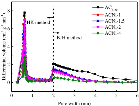
In order to observe the influence of nickel oxide loading on the pore size distribution of activated carbon more intuitively, HK and BJH methods were adopted to calculate the micropore and mesopore size distribution of activated carbon, respectively, based on the nitrogen adsorption-desorption data. The results are shown in Fig. 1.
0 1 2 3 4 5 6
0 2 4 6 8
Diffe
renti
al
vo
lume (c
m
3 g -1 nm -1 )
Pore width (nm)
AC3155 ACNi-1 ACNi-1.5 ACNi-2 ACNi-4 HK method
[image:5.596.176.415.553.736.2]BJH method
It can be seen from the Fig. 1 that although the number of micropore and mesopore of activated carbon loaded with nickel oxide decreases in varying extents, the overall trend of pore size distribution has not changed obviously. The loaded activated carbon is still a high microporous carbon material, and the micropore size mainly distributes in 0.5-1 nm, the mesopore size mainly distributes in 2-4 nm. In addition, compared with other groups of activated carbon, the number of micropore and mesopore of ACNi-4 decreased significantly, which is consistent with the specific surface area and pore volume parameters of ACNi-4 in Table 1.
Although the specific surface area and pore number of the modified activated carbon are decreased, the specific surface area and pore volume of the modified activated carbon are still relatively large when the BNC concentration is low, and the original pore size distribution of the activated carbon is basically maintained after the loading of nickel oxide, so considerable double layer capacitance can still be generated.
3.2 Effect of nickel oxide loading on surface morphology of activated carbon
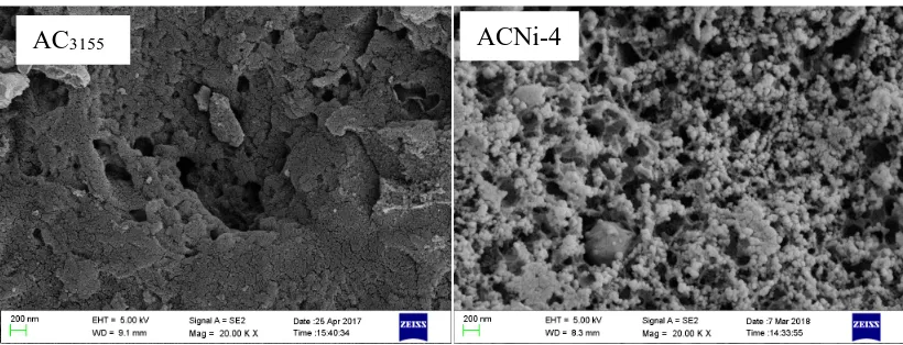
[image:6.596.93.503.514.671.2]Scanning electron microscope (SEM) images of AC3155 and ACNi-4 are shown in Fig. 2. As can be seen from the picture, the surface of the activated carbon before modification is relatively smooth, almost no other granular substances can be observed except for some tiny activated carbon particles. A large number of nanometer scale nickel oxide particles were evenly distributed on the surface of the modified activated carbon, while some tiny particles gathered together and formed larger particles. Which indicates that nickel oxide can be loaded on the surface and pore structure of activated carbon by impregnating activated carbon with BNC solution and pyrolysis at high temperature. In addition, the SEM image of ACNi-4 shows that activated carbon still has abundant pore structure after loading a large amount of nickel oxide.
Figure 2. The surface morphology of AC3155 and ACNi-4
3.3 X-ray diffraction (XRD) of nickel oxide modified activated carbon
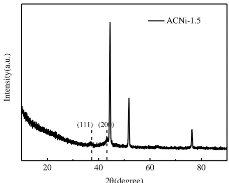
In order to further confirm whether nickel oxide is adsorbed on the surface of activated carbon and the crystal structure of nickel oxide, the modified activated carbon was tested by XRD. The XRD spectrum of ACNi-1.5 is shown in Fig. 3.
20 40 60 80
Intensi
ty(a.
u.)
2(degree)
ACNi-1.5
[image:7.596.187.415.172.354.2](111) (200)
Figure 3. XRD spectrum of ACNi-1.5
It can be clearly seen that the XRD spectrum of activated carbon modified by nickel oxide show sharp characteristic peaks at the positions of 2θ=38° and 43°, corresponding to 111 and 200 crystal planes of nickel oxide, respectively. Which indicates that the nickel oxide is effectively adsorbed on the surface of activated carbon. Due to the low concentration of BNC and the huge specific surface area of activated carbon, the distribution of BNC on the surface of activated carbon is relatively dispersed. Therefore, nickel oxide adsorbed on the surface of activated carbon is less and exists in nanometer scale, which leads to weak characteristic peaks of nickel oxide on the modified activated carbon. In addition, from the XRD spectrum, it can be seen that nickel oxide loaded on the surface of activated carbon is hexagonal phase. Good crystallinity is conducive to the transport of electrolyte ions and charges, thus improving the electrochemical properties of composite carbon electrode materials.
3.4 Electrochemical properties of asymmetric capacitors
Activated carbon modified by nickel oxide was used as positive material and AC3155 was used as negative material to assemble asymmetric capacitors for electrochemical testing.
3.4.1 The mechanism of pseudocapacitance produced by nickel oxide
and discharging, the redox reaction is mainly accomplished by the transfer of protons and electronic defects on the semiconductor lattice. The reversible redox reaction of nickel oxide with alkaline electrolyte during charging and discharging is as follows [28]:
NiO+zOH- ↔ zNiOOH+(1-z)NiO+ze
-During the charging process, the reaction proceeds to the right, and with the transfer of electrons, the divalent nickel is oxidized to trivalent nickel, while the nickel oxide on the electrode reacts with OH -in the electrolyte, result-ing -in the production of nickel oxyhydrogen, charges are also stored -in supercapacitors as the oxidation reaction proceeds. The redox reaction is highly reversible during charging and discharging process, so the nickel oxide electrode usually has excellent charge-discharge efficiency. In addition, the reversible reaction proceeds very quickly in both directions, which can effectively shorten the charging and discharging time of supercapacitors. Therefore, nickel oxide is suitable as the electrode material for supercapacitors. However, there is almost no free OH- in the electrode, and nickel oxide can only react with OH- in the electrolyte. Therefore, the ability of the pore structure of activated carbon to transport OH- is very important. Activated carbon provides large surface area for nickel oxide loading, while reasonable pore structure has strong ion transport capacity. It can provide enough OH- for redox reaction, which is the key to improve the electrochemical properties of composite materials.
3.4.2 Gravimetric capacitance performance of asymmetric capacitors
0 2 4 6 8 10
240 280 320 360 Gravimetr ic ca pacit ance (F g -1)
Current density(A g-1)
AC3155 ACNi-1 ACNi-1.5 ACNi-2 ACNi-4 (a)
0 500 1000 1500 2000
0.2 0.4 0.6 0.8 1.0 Po te ntial (V) Time (s)
0.1 A g-1
0.3 A g-1
0.5 A g-1
1 A g-1
[image:9.596.106.492.74.219.2](b)
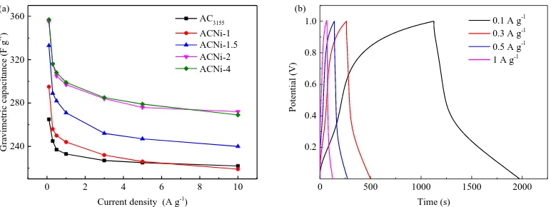
Figure 4. (a) Gravimetric capacitances of modified activated carbon at current densities of 0.1, 0.3, 0.5, 1, 3, 5 and 10 A g-1; (b) Gravimetric capacitances of ACNi-4 at current densities of 0.1, 0.3, 0.5 and 1 A g-1
Fig. 5 shows the relationship between the gravimetric capacitance of nickel oxide modified activated carbon and the concentration of BNC at different current densities. When the concentration of BNC increases from 1×10⁻³ mol L-1 to 2×10⁻³ mol L-1, the gravimetric capacitance of modified activated carbon increases with good linear characteristics, however, the gravimetric capacitance of modified activated carbon remains almost unchanged with the increase of BNC concentration from 2×10⁻³ mol L -1 to 4×10⁻³ mol L-1. With the increase of BNC concentration, more and more nickel oxide is loaded on the surface of activated carbon and produces more pseudocapacitance.
1.0 1.5 2.0 2.5 3.0 3.5 4.0
200 250 300 350 400 450 Gravimetr ic ca pacit ance (F g -1 )
Molarity(10-3
mol L-1
) 0.1 A g-1
[image:9.596.179.416.440.625.2]0.5 A g-1 3 A g-1 10 A g-1
Figure 5. Relationship between gravimetric capacitance of activated carbon and concentration of BNC
carbon, the number of porous structure of activated carbon is significantly reduced, and the double layer capacitance of activated carbon is reduced. In addition, the capacity of pore structure to transport electrolyte ions is also reduced, and enough OH- cannot be transported to react with nickel oxide on the surface of activated carbon, resulting in a decrease in the increase rate of pseudocapacitance. As a result, the gravimetric capacitance of modified activated carbon tends to be stable with the increase of BNC concentration.
3.4.3 Charge-discharge efficiency of asymmetric capacitors
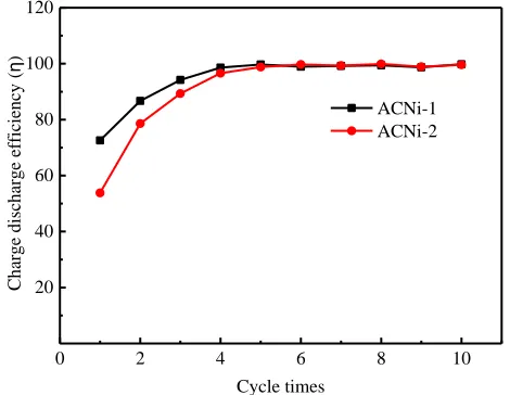
Fig. 6 shows the relationship between charge-discharge efficiency and cycle times of asymmetric capacitors prepared by ACNi-1 and ACNi-2. As can be seen from the Fig. 6, the charge-discharge efficiency of asymmetric capacitors is relatively low at the beginning, only 72.6% and 53.8% respectively. In the process of modification, besides the introduction of nickel oxide, activated carbon will also introduce other impurities, which may react irreversibly with the electrolyte during charging and consume electric energy. In addition, the introduction and increase of some surface functional groups in the modification process may also cause irreversible reaction with electrolyte and consume electric energy. These reasons lead to low initial charge-discharge efficiency of supercapacitors. Compared with ACNi-1/AC3155 asymmetric capacitor, the charge-discharge efficiency of ACNi-2/AC3155 asymmetric capacitor is lower because more impurities and surface functional groups are introduced in the modification process with the increase of BNC concentration. With the increase of cycle times, the charge-discharge efficiency increases gradually, and after five cycles, the efficiency is almost stable at 100%. With the increase of charging and discharging times, the impurities and surface functional groups which react irreversibly with electrolyte in activated carbon are gradually consumed completely, and almost all the electric energy during charging process is stored in the form of double layer capacitance and pseudocapacitance. The nearly 100% charge-discharge efficiency of asymmetric capacitors also represents that the redox reaction between nickel oxide and alkaline electrolyte is highly reversible.
0 2 4 6 8 10
20 40 60 80 100 120
Ch
arge
dischar
ge ef
fic
ie
ncy
(
η
)
Cycle times
[image:10.596.181.416.540.722.2]ACNi-1 ACNi-2
3.4.4 Cyclic voltammetric characteristics of asymmetric capacitors
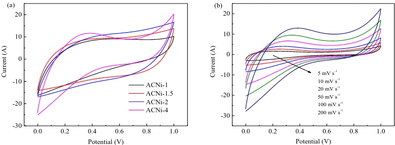
Fig. 7 shows the cyclic voltammetric curves of four groups of asymmetric electrodes at a voltage scanning rate of 200 mV s-1. It can be seen from the figure that the cyclic voltammetric curve of asymmetric capacitors assembled by nickel oxide modified activated carbon and sargassum-based activated carbon is not a standard rectangle, which represents that asymmetric capacitors have both double layer capacitance and pseudocapacitance.
0.0 0.2 0.4 0.6 0.8 1.0
-30 -20 -10 0 10 20
Cu
rre
nt (A)
Potential (V)
ACNi-1 ACNi-1.5 ACNi-2 ACNi-4 (a)
0.0 0.2 0.4 0.6 0.8 1.0
-30 -20 -10 0 10 20
Cu
rre
nt (A)
Potential (V)
5 mV s-1
10 mV s-1
20 mV s-1
50 mV s-1
100 mV s-1
200 mV s-1
[image:11.596.101.491.204.348.2](b)
Figure 7. (a) The cyclic voltammetric curves of asymmetric capacitors at scan rate of 200 mV s-1; (b) The cyclic voltammetric curves of ACNi-4/AC asymmetric supercapacitor measured at different scan rates of 5, 10, 20, 50, 100, and 200 mV s−1
3.4.5 Equivalent series resistance of asymmetric capacitors
0 1 2 3 4
0.15 0.20 0.25 0.30 0.35 0.40
Resi
st
ence
(Ω)
[image:12.596.182.414.75.262.2]Molarity (10-3 mol L-1)
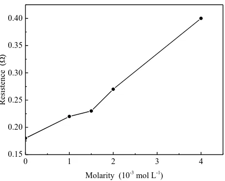
Figure 8. Equivalent series resistance of asymmetric capacitors at current density of 1 A g-1
3.4.6 Cyclic performance of asymmetric capacitors
0 2000 4000 6000 8000 10000
0 20 40 60 80 100
Retent
ion (
%)
Cycle times ACNi-2
[image:13.596.160.446.75.299.2]AC3155
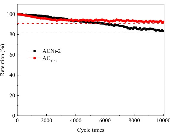
Figure 9. Cyclic performance of asymmetric capacitors at current density of 5 A g-1
4. CONCLUSION
In this study, BNC with low concentration was used to impregnate activated carbon. The impregnated activated carbons were pyrolyzed at high temperature in nitrogen atmosphere to accomplish the loading of nickel oxide on the surface of activated carbon. Nickel oxide modified activated carbon and sargassum-based activated carbon were assembled into asymmetric capacitors to study their electrochemical properties.
(1) According to nitrogen adsorption-desorption, XRD and SEM tests, a large number of nanometer scale nickel oxide particles are adsorbed on the surface of activated carbon, and the modified activated carbon still have abundant pore structure.
(2) Compared with the symmetrical capacitor assembled by AC3155, the gravimetric capacitance of the asymmetrical capacitor assembled by nickel oxide modified activated carbon and AC3155 is obviously increased. With the increase of the concentration of BNC solution, the gravimetric capacitance increases gradually, but the increase rate slows down.
(3) Compared with symmetrical capacitor, the equivalent series resistance of asymmetrical capacitors assembled with modified activated carbon increases due to the poor conductivity of nickel oxide, and the resistance of capacitor increases gradually with the increase of nickel oxide content.
ACKNOWLEDGEMENTS
The authors are grateful to the Shandong University for providing equipment support. This study was supported by the Doctoral Fund of Shandong Jianzhu University (XNBS1838), Fundamental Research Funds of Shandong University (2016JC005), Natural Science Foundation of Shandong, China (ZR2017MEE010) and Shandong Provincial Natural Science Foundation (ZR2019BEE059).
References
1. S.J. Li, K.H. Han, P.C. Si, J.X. Li, C.M. Lu, J. Electroanal. Chem., 820 (2018) 103–110. 2. V. Augustyn, P. Simon, B. Dunn, Energy. Environ. Sci., 7 (2014) 1597.
3. D.Y. Kang, J.H. Moon, ACS Appl. Mater. Interfaces, 6 (2014) 706–711. 4. L. Wei, G. Yushin, J. Power Sources, 196 (2011) 4072–4079.
5. R. Kötz, M. Carlen, Electrochim. Acta, 45 (2000) 2483–2498. 6. E. Frackowiak, F. Beguin, Carbon, 39 (2001) 937–950. 7. A. Burke, Electrochim. Acta, 53 (2007) 1083–1091.
8. P. Simon, Y. Gogotsi, Acc. Chem. Res., 46 (2012) 1094–1103.
9. Y.P. Zhai, Y.Q. Dou, D.Y. Zhao, P.F. Fulvio, R.T. Mayes, S. Dai, Adv. Mater., 23 (2011) 4828– 4850.
10.W. Zhang, Y.H. Yao, L.J. Gao, Chin. Chem. Lett., 23 (2012) 623–626.
11.D.L. Castello, D.C. Amoros, A.L. Solano, S. Shiraishi, H. Kurihara, A. Oya, Carbon, 41 (2003) 1765–1775.
12.A. Jain, C. Xu, S. Jayaraman, R. Balasubramanian, J.Y. Lee, M.P. Srinivasan, Microporous Mesoporous Mater., 218 (2015) 55–61.
13.S. Faraji, F.N. Ani, Renew. Sustain. Energy Rev., 42 (2015) 823–834.
14.M.Y. Cho, M.H. Kim, H.K. Kim, K.B. Kim, J.R. Yoon, K.C. Roh, Electrochem. Commun., 47 (2014) 5–8.
15.M. Endo, T. Maeda, T. Takeda, Y.J. Kim, K. Koshiba, H. Hara, J. Electrochem. Soc., 148 (2001) A910–A914.
16.Q. Cheng, J. Tang, J. Ma, H. Zhang, N. Shinya, L.C. Qin, Phys. Chem. Chem. Phys., 13 (2011) 17615–17624.
17.Z. Wu, X.B. Zhang, Sci. China. Mater., 59 (2016) 547–557.
18.A. González, E. Goikolea, J. A. Barrena, R. Mysykb, Renew. Sust. Energ. Rev., 58 (2016) 1189– 1206.
19.P. Simon, Y. Gogotsi, Nat. Mater., 7 (2008) 845–854.
20.R. Farma, M. Deraman, A. Awitdrus, I.A. Talib, E. Taer, N.H. Basri, J.G. Manjunatha, M.M. Ishak, B.N.M. Dollah, S.A. Hashmi, Bioresour. Technol., 132 (2013) 254–261.
21.X.S. Feng, Y. Huang, C. Li, X.F. Chen, S.H. Zhou, X.G. Gao, C. Chen, Chem. Eng. J., 368 (2019) 51–60.
22.J.G. Ju, Y. Lv, L.Y. Wang, W.C. Liu, Z.J. Li, W.M. Kang, B.W. Cheng, J. Electrochem. Soc., 166 (2019) A1223–A1230.
23.Z.J. Fan, J.Yan, T. Wei, L.J. Zhi, G.Q. Ning, T.Y. Li, F. Wei, Adv. Funct. Mater., 21 (2011) 2366– 2375.
24.V. Ganesh, S. Pitchumani, V. Lakshminarayanan, J. Power Sources, 158 (2006) 1523–1532. 25.Z.S. Wu, G.M. Zhou, L.C. Yin, W.C. Ren, F. Li, H.M. Cheng, Nano Energy, 1 (2017) 107–131. 26.Y.H. Wang, P. He, X.M. Zhao, W. Lei, F.Q. Dong, J. Solid. State. Electr., 18 (2014) 665–672. 27.S.J. Li, K.H. Han, J.X. Li, M. Li, C.M. Lu, Microporous Mesoporous Mater., 243 (2017) 291–300. 28.J.P. Cao, S. He, Y. Wu, X.Y. Zhao, X.Y. Wei, T. Takarada, Int. J. Electrochem. Sci., 12 (2017) 2704
– 2718.
665–672.
30.C.H. Kim, B.H. Kim, J. Power Sources, 274 (2015) 512-520.
31.M. Kim, Y. Hwang, K. Min, J. Kim, Electrochim. Acta, 113 (2013) 322–331.
32.L.Q. Fan, G.J. Liu, J.H. Wu, L. Liu, J.M. Lin, Y.L. Wei, Electrochim. Acta, 137 (2014) 26–33. 33.X. Du, C.Y. Wang, M.M. Chen, Y. Jiao, J. Wang, J. Phys. Chem., C 113 (2009) 2643–2646.