Int. J. Electrochem. Sci., 14 (2019) 1698 – 1712, doi: 10.20964/2019.02.11
International Journal of
ELECTROCHEMICAL
SCIENCE
www.electrochemsci.org
Numerical Simulation of the Effects of Obstacles in Gas Flow
Fields of a Solid Oxide Fuel Cell
Qiuwan Shen1,*, Lina Sun2, Baowen Wang3
1 Marine Engineering College, Dalian Maritime University, Dalian,116026, China 2 Petroleum Engineering College, Yangtze University, Wuhan 430100, China
3 College of Electric Power, North China University of Water Resources and Electric Power,
Zhengzhou, 450045, China
*E-mail: [email protected]
Received: 18 September 2019 / Accepted: 23 November 2019 / Published: 5 January 2019
In this study, the local transport phenomena and overall cell performance of a single planar anode-supported solid oxide fuel cell with/without rectangular obstacles inside the anode and cathode gas flow channels are numerically investigated by using a three-dimensional mathematical model. Numerical results of two cases including temperature distribution, species concentration distribution, and current density distribution are reported and compared. The results indicate that the maximum temperature of the fuel cell with obstacles is about 5 K lower than that of the fuel cell without obstacles. It is also observed that the hydrogen utilization is improved and a more uniform oxygen distribution is obtained due to the presence of rectangular obstacles. In addition, the pressure drop penalty of the fuel cell with obstacles is greatly increased.
Keywords: Solid Oxide Fuel Cells, Numerical modeling, Gas flow channel geometry, Obstacles
1. INTRODUCTION
The local transport characteristics and overall cell performance is significantly affected by the flow field design. The heat and mass transport characteristics in fuel cell ducts with rectangular and trapezoidal cross-section were numerically investigated [13]. Numerical studies were performed to investigate the effect of geometric parameters on the flow uniformity in planar SOFC stacks [14]. An innovative shape was adopted to improve the cell performance [15]. Nickel foam and metallic corrugated structure were used as gas distributor and current collector in the anode and cathode sides of SOFCs, respectively [16]. Recently, the gas transport process and cell performance were significantly improved when finger-like channels were employed in SOFCs [17]. The cell performance of SOFCs with woven meshes as the anode flow field was experimentally investigated and reported [18]. The cell performance of SOFCs with six different flow field designs was numerically studied and compared [19].
Understanding the detailed transport phenomena occurring within SOFCs is an expensive and challenging procedure. Therefore, numerical simulation plays an important role in predicting the local transport processes and overall performance of SOFCs. An appropriate design of flow field channel is beneficial to the reactant gas transport as well as the cell performance. In this present study, the cell performance of a planar anode-supported SOFC with rectangular obstacles inside the anode and cathode gas channels have been investigated and compared with that with straight gas flow channels.
In the three-dimensional mathematical model, the mass, momentum, species, energy and charge conservation equations are simultaneously solved. With the simulation results, the local temperature distributions and the species concentration distributions of the fuel cells with/without obstacles are presented and discussed. In addition, the current density distributions and pressure drop are also presented.
2. MODEL AND NUMERICAL METHOD
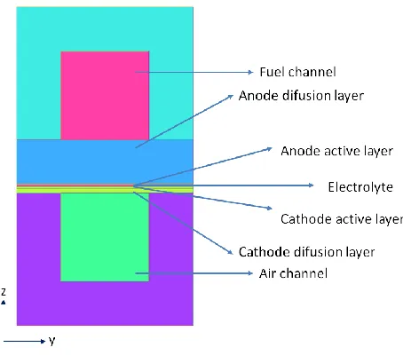
[image:2.596.192.419.515.715.2]2.1 Model geometry
Schematic illustration of the proposed fuel cell physical model can be seen in Figure 1 and Figure 2. In the anode and cathode gas flow channels, five rectangular obstacles are located in the middle of the channel. The geometric parameters of the model are summarized in Table 1.
[image:3.596.74.523.156.240.2]Figure 2. The SOFC with obstacles inside gas flow channels.
Table 1. Fuel cell geometry parameters
Parameters Value Units
Cell length 40 mm
Cell width 2 mm
Channel width 1 mm
Channel height 1 mm
Anode diffusion layer thickness 0.5 mm
Anode active layer thickness 0.02 mm
Cathode active layer thickness 0.02 mm Cathode diffusion layer thickness 0.05 mm
Electrolyte thickness 0.01 mm
Interconnect height 1.5 mm
Obstacle height 0.5 mm
Obstacle length 1 mm
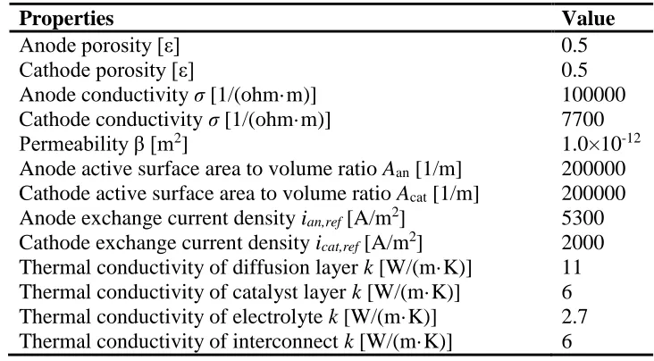
Table 2. Properties for different components
Properties Value
Anode porosity [ε] 0.5
Cathode porosity [ε] 0.5
Anode conductivity σ [1/(ohm·m)] 100000
Cathode conductivity σ [1/(ohm·m)] 7700
Permeability β [m2] 1.0×10⁻¹²
Anode active surface area to volume ratio Aan [1/m] 200000
Cathode active surface area to volume ratio Acat [1/m] 200000
Anode exchange current density ian,ref [A/m2] 5300
Cathode exchange current density icat,ref [A/m2] 2000
[image:3.596.144.461.310.496.2] [image:3.596.113.479.536.738.2][image:4.596.171.425.115.337.2]
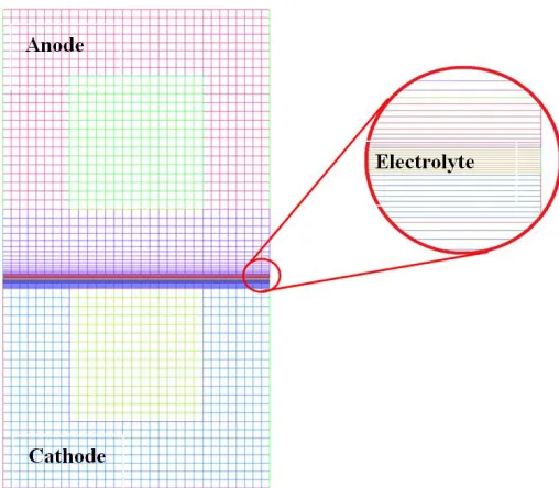
The parameters used in the mathematical model are summarized in Table 2. The mesh density in different zones is varied to ensure the accuracy of computations, as shown in Fig.3.
Figure 3. Mesh of the computational domain.
2.2 Model assumptions
The assumptions used in this study are as follows: (1) The fuel cell is under steady state.
(2) The fluid flow in the gas channels is laminar flow. (3) The ideal gas law is applied for reactant gases.
(4) The diffusion and active layers are homogeneous and isotropic.
2.3 Governing equations
In the three-dimensional mathematical model, the conservation equations of mass, momentum species, momentum, energy and charge were solved using the finite-volume method. The solid and fluid domains were divided into discrete meshes, and the equations are specified for various zones in the full cell.
The continuity conservation equation: ∇(𝜌𝑈) = 𝑆𝑚 (1)
where ρ is the mixture density. Sm, source term is expressed as:
𝑆𝑚 = {∑ 𝑆𝑖 𝑚,𝑖 𝑎𝑐𝑡𝑖𝑣𝑒 𝑙𝑎𝑦𝑒𝑟𝑠
0 𝑜𝑡ℎ𝑒𝑟𝑠
The momentum conservation equation:
where U is the velocity vector, P is the pressure and μ is the dynamic viscosity. Sd, source term
is described as:
𝑆𝑑 = {−0 𝑜𝑡ℎ𝑒𝑟𝑠𝜇 𝛽𝑈 𝑎𝑐𝑡𝑖𝑣𝑒 𝑎𝑛𝑑 𝑑𝑖𝑓𝑓𝑢𝑠𝑖𝑜𝑛 𝑙𝑎𝑦𝑒𝑟𝑠
where β is the permeability of the porous structure.
The species conservation equation:
∇(𝜌𝑈𝑌𝑖) = ∇(𝜌𝐷∇𝑌𝑖) + 𝑆𝑚,𝑖 (3) where Yi is the mole fraction of the ith species, D is the mass diffusion coefficient and Sm,iis the
source term resulting from chemical reactions. The Stefan-Maxwell equation is used to calculate the gas species mass diffusivity.
Sm,i , source terms is expressed as:
𝑆𝑚,𝑖 = { 𝑗
𝑛𝑒 𝐹𝑀𝑖 𝑎𝑐𝑡𝑖𝑣𝑒 𝑙𝑎𝑦𝑒𝑟𝑠
0 𝑜𝑡ℎ𝑒𝑟𝑠
where 𝑀𝑖 is the molecular weight of the ith species and J is the current density.
The energy conservation equation:
∇(𝜌𝐶𝑝𝑈𝑇) = ∇(𝑘𝑒𝑓𝑓∇𝑇) + 𝑆𝑇 (4)
where keff is the effective thermal conductivity of the solid and gas phases. ST, source term
accounts the ohmic heating, activation losses, the reversible heat due to electrochemical reactions and the heat of chemical reactions. Ohmic heating takes place in the electrolyte and electrodes while the other heat source terms are located in the active layers.
𝑘𝑒𝑓𝑓 = (1 − 𝜀)𝑘𝑠+ 𝜀𝑘𝑓
𝑆𝑇 = { 𝑗2
𝜎 + 𝑗 ∙ 𝜂𝑎𝑐𝑡 + 𝑗
𝑛𝑒 𝑇Δ𝑆 𝑎𝑐𝑡𝑖𝑣𝑒 𝑙𝑎𝑦𝑒𝑟𝑠
0 𝑜𝑡ℎ𝑒𝑟𝑠
where 𝜂𝑎𝑐𝑡 is the activation potential, Δ𝑆 is the entropy change associated with the electrochemical reactions, and 𝜎 is the electrical conductivity.
The charge conservation equation: (sol sol) Ss 0
(5) (ionic ionic) Sionic 0
(6) Where σ is electrical conductivity, is electric potential, and S is the source term.
(10300/ ) 100 0.3685 0.002838 ionic T e 𝑆𝑠 = {
−𝑗𝑎 𝑎𝑛𝑜𝑑𝑒 𝑎𝑐𝑡𝑖𝑣𝑒 𝑙𝑎𝑦𝑒𝑟
𝑗𝑐 𝑐𝑎𝑡ℎ𝑜𝑑𝑒 𝑎𝑐𝑡𝑖𝑣𝑒 𝑙𝑎𝑦𝑒𝑟 𝑆𝑖𝑜𝑛𝑖𝑐 = {𝑗𝑎 𝑎𝑛𝑜𝑑𝑒 𝑎𝑐𝑡𝑖𝑣𝑒 𝑙𝑎𝑦𝑒𝑟
−𝑗𝑐 𝑐𝑎𝑡ℎ𝑜𝑑𝑒 𝑎𝑐𝑡𝑖𝑣𝑒 𝑙𝑎𝑦𝑒𝑟
The source term Ss and Sionic are described by the Butler-Volmer functions: 2 2 1 2 . . ( )
aF a cF a
H RT RT
a an ref an H ref c
j i A e e
c 2 2 . . ( )
cFc aF c
O RT RT
c cat ref cat O ref c
j i A e e
a sol ionic
c sol ionic Voc
2.4. Boundary conditions and solution methods
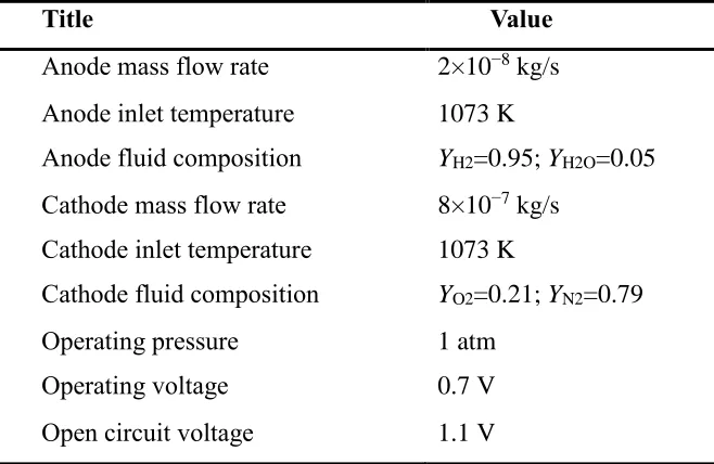
[image:6.596.139.468.303.517.2]The computational domain consists of a single cell which operates in counter-flow, i.e., the fuel flow direction is opposite to the oxygen flow direction. A three-dimensional model is implemented using the commercial software ANSYS FLUENT with its fuel cell add-on module. The input parameters and boundary conditions for the two geometries depicted in Fig.1 are shown in Table3.
Table 3. Parameters used in simulation
Title Value
Anode mass flow rate 2×10⁻⁸ kg/s Anode inlet temperature 1073 K
Anode fluid composition YH2=0.95; YH2O=0.05
Cathode mass flow rate 8×10⁻⁷ kg/s Cathode inlet temperature 1073 K
Cathode fluid composition YO2=0.21; YN2=0.79
Operating pressure 1 atm
Operating voltage 0.7 V
Open circuit voltage 1.1 V
3. SIMULATION RESULTS AND DISCUSSION
3.1 Temperature distribution
Figure 4. Temperature distribution at different positions along gas flow direction (x=0.001m, 0.01m, 0.02m, 0.03m, 0.039m): (a) straight channel; (b) channel with obstacles.
0,00 0,01 0,02 0,03 0,04
1290 1300 1310 1320 1330 1340 1350 1360 1370
T
e
mp
e
ra
tu
re
(K)
x flow direction (m)
channel without obstacles channel with obstacles
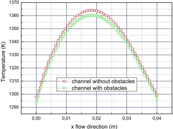
Figure 5. Comparasion of temperature distribution along the middle line of the active area of two different channels.
[image:7.596.98.497.123.309.2] [image:7.596.129.459.362.608.2]
flow arrangements (co-flow, counter-flow, and cross-flow) [20]. It is also observed that the maximum temperature obtained in the fuel cell with obstacles is about 5 K lower than that without obstacles. It is indicated that the temperature gradient is decreased due to the presence of obstacles in the flow channels. When the temperature gradient is too high, it is harmful to the performance and lifetime of the SOFCs. Therefore, the application of obstacles in the gas flow channels has a potential ability to obtain a more uniform temperature distribution in the fuel cell.
3.2. Mass transport characteristics 3.2.1Hydrogen distribution
As shown in Figure 6, the mole fraction distribution of hydrogen is presented for both fuel cells with/without obstacles.
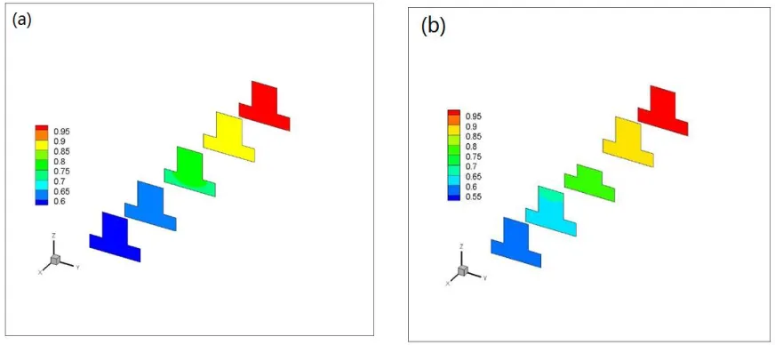
Figure 6. Hydrogen mole fraction in the anode side at different positions along gas flow direction (x=0.001m, 0.01m, 0.02m, 0.03m, 0.039m): (a) straight channel; (b) channel with obstacles.
With the consumption of hydrogen and generation of water caused by the electrochemical reaction, the mole fraction of hydrogen decreases from the inlet to the outlet. As can be seen in Figure 6, the mole fractions of hydrogen at the inlet and outlet are 0.95 and 0.6, respectively. Thus, the fuel utilization of the fuel cell without obstacles is about 0.37. Compared with the fuel cell without obstacles, the fuel cell with obstacles has a smaller mole fraction at the flow channel outlet which is about 0.55. The fuel utilization of the fuel cell with obstacles is about 0.42. The application of obstacles in gas flow channels increases the hydrogen utilization, which is expected for the fuel cell.
3.2.2 Oxygen distribution
[image:8.596.79.515.309.503.2]
distribution in the cathode along the middle line of the active area of two different channels. It can be seen that oxygen mole fraction decreases along the flow direction for both cases due to the consumption of the oxygen, which is needed for the electrochemical reaction. In addition, the oxygen mole fraction of the fuel cell with obstacles is higher than that of fuel cell without obstacles, especially at the regions where the obstacles are placed. It is also observed that the oxygen mole fraction is higher at the regions under the channels that that at the regions under the ribs. That is because the oxygen diffusion to the regions under the ribs is limited by the diffusion lengths. The variation of oxygen distribution along the flow direction is obtained due to the existence of obstacles in the gas flow channel. The similar behavior was also observed in the fuel cells with wavy surface cathode gas flow channel [22].
Figure 7. Oxygen mole fraction in the cathode side at different positions along gas flow direction (x=0.001m, 0.01m, 0.02m, 0.03m, 0.039m): (a) straight channel; (b) channel with obstacles.
0.00 0.01 0.02 0.03 0.04
0.12 0.13 0.14 0.15 0.16 0.17 0.18 0.19 0.20
O2
mo
le
fra
ct
io
n
[image:9.596.75.522.242.440.2]X flow direction (m) channel without obstacles channel with obstacles
[image:9.596.168.420.505.692.2]
3.3. Current density distribution
0.0 0.5 1.0 1.5 2.0
0.2 0.4 0.6 0.8 1.0 1.2
Vol
ta
g
e
(V)
Current density (A/m2
)
channel without obstacles channel withobstacles
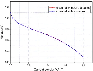
Figure 9. Comparison of polarization curves between the two different fuel cells.
[image:10.596.129.456.107.357.2] [image:10.596.173.433.406.675.2]
Figure 11. Current density distribution at different positions along the main flow direction for the fuel cell with obstacles.
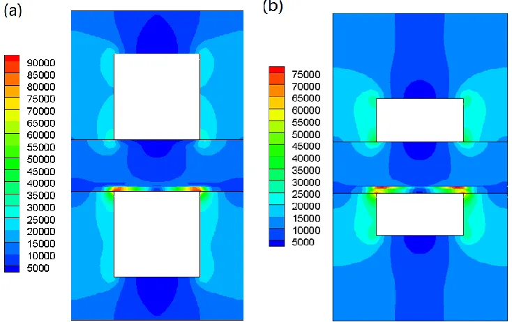
Figure 12. Current density distribution in x=0.2 m along the main flow direction: (a) straight channel; (b) channel with obstacles.
[image:11.596.171.432.73.339.2] [image:11.596.110.477.395.626.2]
be affected by the position, size, number and shape of the obstacles in the gas flow channels, which should be further studied. Figure 10 and 11 depict the current density distribution in different positions along the main flow direction for the two different cases.
In Figures 10 and 11, it can be seen that the current density distribution is uneven for both two channel geometry fuel cell. It is shown that the highest current density appears in the cathode side at the corners between ribs and electrode. At the anode side, it is also has the same trend, but the maximum value is much smaller than the cathode side which is due to the relative thick anode layer.
Figure 12 compares the current density distribution in the middle of the channel (x=0.2 m) along the main flow direction for the two full cells. It is found that the maximum cuurent density of fuel cell without obstacles is larger that that of fuel cell with obstacles, which is mainly attributed to the temperature distribution and the presence of obstacle. The electron transport resistance is increased due to the increase in interconnect thickness. A higher current density results in a higher over potential and a higher ohmic heat generation in fuel cells. Both the uneven and higher current density are harmful to the fuel cell performance and lifetime.
3.4. Pressure drop
0 20 40 60 80 100 120
Channel with obstacles Cathode
Anode
Pre
ssu
re
d
ro
p
(Pa
)
Channel without obstacles Anode
[image:12.596.129.451.392.626.2]Cathode
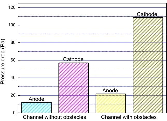
Figure 13. Pressure drop in anode and cathode of the two different fuel cells.
It also can be seen that with the obstacles inside the gas flow channel, the pressure drop increased almost by one time compared with the channel without obstacles. It is obvious that the pressure drop is greatly increased when the obstacles are adopted in the gas flow channel. The similar results were also reported in the previous literature [22]. In addition, the pressure drop is significantly affected by the cross-sectional shape [13, 15, 23] and flow field design [16, 17, 19, 24].
4. CONCLUSIONS
A three-dimensional mathematical model has been employed to investigate the performance of fuel cells with/without obstacles in the gas flow channels. Simulation results including distributions of temperature, species concentration and current density inside fuel cells are presented. The results indicate that the maximum temperature of the fuel cell with obstacles is about 5 K lower than that of the fuel cell without obstacles. The application of obstacles in gas flow channels increases the hydrogen utilization which is expected for the fuel cell. The maximum current density appears in the cathode side at the corners between ribs and electrode. The average current density is almost the same for both cases. However, the local current density is significantly affected by the presence of obstacles. The effects of position, size, number and shape of the obstacles in the gas flow channels can be further studied.
NOMENCLATURE:
A Specific active surface area,1/m CP Specific heat, J/(kg·K)
D Diffusion coefficient, m2/s F Faraday constant, 96487 C/mol i Exchange current density, A/m2
j Transfer current density, A/m3 k Thermal conductivity, W/(m·K) M Molecular weight, kg/mole
ne Number of electrons transferred per reaction
P Pressure , Pa
R Universal gas constant, 8314J/(mol·K) S Entropy, kJ mol-1 K-1
S Source term T Temperature, K U Velocity vector, m/s
V Voltage, V
Yi Mole fraction of species i
Greek Symbols β Permeability , m2
ε Porosity
η Overpotential, V
ρ Density, kg/m3
σ Electrical conductivity, 1/ohm m Φ Electric potential, V
Subscripts
an Anode
cat Cathode
eff Effective
i Gas species i
m Momentum
oc Open circuit
ohm Ohmic
ACKNOWLEDGEMENT
The authors acknowledge the financial supports of the National Natural Science Foundation of China (No.51606013).
References
1. L.Q. Fan, Y.P. Xiong, L.B. Liu, Y.W. Wang, M.E. Brito, Int. J. Electrochem. Sci. 8 (2013) 8603-8613.
2. T.C. Patil, S.M. Mahajani, S.P. Duttagupta, Int. J. Electrochem. Sci. 9 (2014) 8458-8464. 3. M. Peksen, Int. J. Hydrogen Energy 39 (2014) 5137-5147.
4. S.C. Su, S.D. Zhang, C. Yan, Z.M. Yang, F. Zhang, L. Zhang, Int. J. Electrochem. Sci. 12 (2017) 230-239.
5. Z. Yu, S. Liu, F. Zheng, Y. Ding, Int. J. Electrochem. Sci. 11 (2016) 10210-10222. 6. K. Lou, F.H. Wang, X. Zhao, Y.J. Lu, Int. J. Electrochem. Sci. 11 (2016) 1382-1394. 7. S. Liu, W. Kong, Z. Lin, J. Power Sources, 194 (2009) 854-863.
8. B.A. Haberman, J.B. Young, Int. J. Heat Mass Transfer, 47 (2004) 3617-3629. 9. D. Larrain, J. Van, D. Favrat, J. Power Sources, 161 (2006) 392-403.
10.Y. Wang, F. Yoshiba, T. Watanabe, S. Weng, J. Power Sources, 170 (2007) 101-110.
11.D. Martin, D.M. Guinea, B. Moreno, L. Gonzalez, M.C. Garcia, D. Guinea, Int. J. Hydrogen Energy, 32 (2007) 1572-1581.
12.A. Chaisantikulwat, C. Diaz-Goano, E.S. Meadows, Comput. Chem. Eng., 32 (2008) 2365-2381. 13.J.L. Yuan, M. Rokni, B. Sundén, Int. J. Heat Mass Transfer, 44 (2001) 4047-4058.
14.W. Bi, D. Chen, Z. Lin, Int .J. Hydrogen Energy, 34 (2009) 3873-3884. 15.K.L. Christman, M.K. Jensen, J. Fuel Cell Sci. Technol., 8 (2011) 024501.
16.D. Yan, Z. Bin, D.W. Fang, J. Luo, X.P. Wang, J. Pu, B. Chi, L. Jian, Y.S. Zhang, Int. J. Hydrogen Energy, 38 (2013) 660-666.
17.B. Chen, H.R. Xu, M. Ni, Sci. Bull., 61 (2016) 1324-1332.
18.M. Canavar, B. Timurkutluk, J. Power Sources, 346 (2017) 49-55.
19.M. Saied, K. Ahmed, M. Nemat-Alla, M. Ahmed, M. El-Sebaie, Int. J. Hydrogen Energy, 42 (2018) 20931-20946.
20.Z. Zhang, D. Yue, G Yang, J. Chen, Y. Zheng, H. Miao, W. Wang, J. Yuan, N. Huang, Int. J. Heat Mass Transfer, 84 (2015) 942-954.
21.J. Park, D. Kim, J. Baek, Y. Yoon, P. Su, S. Lee, Energies, 11 (2018) 473.
031007.
23.I. Khazzee, A. Rava, Energy, 119 (2017) 235-244. 24.J. Shi, X. Xue, Chem. Eng. J, 163 (2010) 119-125.