Theses
Thesis/Dissertation Collections
1980
The CMS-2 subset compiler
J. T. Badura
Follow this and additional works at:
http://scholarworks.rit.edu/theses
This Thesis is brought to you for free and open access by the Thesis/Dissertation Collections at RIT Scholar Works. It has been accepted for inclusion
in Theses by an authorized administrator of RIT Scholar Works. For more information, please contact
Recommended Citation
'rh l s
1
5
t
o c
e
rt
i f y
t
ha t
n n .ha
s
5ub
",l
tt
e d
d
t
ne
s
t
s
e
llli
t
l e
d
:
_
Z2;~
_n
_
_
(
:tJ_
?
~
-:_
?_n
5~
.~~
.!Y:.t.
__
~(;::
':l='-,/-~'::
_
t
o
th
e
faCil
I t
y
o
f
the
Sc
h ool
of
COl'l p
u
ter
se
r
e
e
c
e
a
nll
T
ec
hn o log
y
i
n
pol r tl .a l
ru
t
rt
r
t
r.
e m
o
f
t
he
re
Cl\llre
n
e
n
t
~
f
or
Submitted
by:
TABLE
OF
CONTENTS
1
.Introduction
2
Host
System
2
The
CMS-2
Language
2
Target
Machine
2
Purpose
ofthe
CMS-2
Compiler
4
Compiler
Design
Objectives
4
2.
.OverviewofCompiler
Structure
6
Debugging
Features,
8
3.
Overview
ofthe
Metatranslator
9
4.
Symbol
Table
11
5.
Pass
One
14
Lexical
Analysis
14
Syntactic
Analysis
15
Storage
Allocation
19
Cross
Reference
Table
21
Intermediate
Language
22
6.
Pass
Two
24
Pinhole
Optimizations
24
Temp
Compression
27
Temp Commuting
28
Constant
Folding
28
Goto
To
Goto
Elimination
29
Elimination
ofInaccessible
Code
31
Direct
Transfers
31
Exit
Switching
31
7.
Pass
Three
33
Listing
Generation/Error
Checking
34
Direct
Code
35
Code
Generation/Storage
Allocation
35
Comment
Generation
39
Machine
Dependent
Optimization
39
8.
Pass
Four
47
Branches/Subroutine
Calls
47
Entry/Return
Protocol
48
9.
Conclusions
51
INTRODUCTION
The
CMS-2
compiler representsthe
culmination of an effortto
construct a production compiler
for
military
applications.The
materialthat
follows
is
an effortto
render succinct explanations ofthe
structure and rationalebehind
the
compilerdesign.
The
thesis
containedherein
is
submittedin
fulfillment
ofthe
Master
ofScience
degree
in
Computer
Science
atRochester
Institute
ofTechnology.
HOST
SYSTEM
The
CMS-2
compiler wasdeveloped
onthe
the
DEC-10
atMCDONNELL
DOUGLAS
in
Huntington
Beach,
California.
The
DEC-10
runs under aTOPS-10
Operating
System
using
aKL-10
processor.The
machine possesses256K
words of memory.A
variety
of softwaretools
were usedfor
the
construction ofthe
compiler.For
example,
the
front
end ofthe
compiler was writtenusing
the
Metatranslator
, a compiler-compiler
that
generates
FORTRAN.
A
few
ofthe
early
semantic routines were writtenin
FORTRAN,
whilethe
remainder ofthe
compiler was writtenin
FRAN,
whichis
a structured pre-processorfor
FORTRAN.
Lastly,
astring
manipulation routine was writtenin
MARCO-10,
the
assembly
language
ofthe
DEC-10.
THE
CMS-2
LANGUAGE
CMS-2
is
aNavy
language
that
is
specializedfor
realtime
applications.
One
notablefeature
ofthis
language
is
its
capability
for
fixed
point operations.The
only
recognizedCMS-2
compileris
the
onedeveloped
by
the
United
States
Navy.
The
Navy's
compiler will compilefor
eitherthe
AN/UYK-7
orAN/UYK-20(V)
computers.The
compilerdescribed
in
this
report compilesfor
a subset ofthe
originalCMS-2
language.
TARGET
MACHINE
The
target
machinefor
the
compileris
the
MDAC
476CX
microprocessor,
whichis
essentially
a single accumulator-one address machine.The
476CX
possesses8
bit
data
words and16
bit
addresses.The
accumulatoris
registerA
, whichmay
be
used
for
single precision operations.For
double
precision,
the
register pairAB
is
used.The
machine contains A' and B', which
before
the
load.
The
samerelationship
holds
for
B
andB'.
As
for
hardware,
the
microprocessor possesses a181
ALU
chip.PURPOSE
OF
THE
CMS-2
SUBSET
COMPILER
The
CMS-2
compileris
essentially
a cross compilerthat
produces aninput
file
to
the
476CX
assembler, whichis
alsohosted
onthe
DEC-10.
The
assembler generates an objectfile
that
inputs
to
the
476CX
linkage
editor,
producing
a relocatableload
module.
This
load
moduleis
then
usedto
programPROM
chipsfor
the
476CX
microprocessor.In
essence,
the
intended
use ofthe
compileris
to
act as a partialtranslation
step
in
multiple crosstranslations.
COMPILER
DESIGN
OBJECTIVES
The
compiler wasdesigned
according
to
sixfundamental
design
goals,, which arelisted
below:
1
.The
compiler will generate optimalassembly
codethat
will execute as
fast
as possible.This
wasthe
primeobjective,
sincethe
target
machine willbe
usedfor
real
time
applications.Therefore,
the
compiler will gene-ratethe
minimum number ofassembly
language
instructions
andtake
advantage ofthose
instructions
that
areless
expensive.2.
The
compiler will optimize storage allocation ofvariables and
temporaries.
The
minimum number oftemporaries
willbe
generated whilethe
allocation positions of variables willbe
optimalfor
code generation .3.
The
compiler willbe
flexible.
In
the
future,
if
it
is
desired
to
generateassembly
language
for
a newtarget
machine,
only
the
third
andfourth
pass willbe
changed.
(In
allprobability
afourth
pass will notbe
needed sinceit
performs code generationthat
is
uniqueto
the
476).
If
alanguage
otherthan
CMS-2
is
neededto
be
translated
into
476CX
assembly
code,
only
the
first
pass willbe
rewritten.Therefore,
the
CMS-2
compiler will
be
reconfigurable
for
future
needs.4.
The
compiler will generateassembly
codethat
is
clear and readableto
the
user.User
namesfor
variables andlabels
willbe
carriedthrough
to
the
assembly
language
file.
Compiler
generatedlabels
andtemporaries
willbe
distinguishable
from
userlabels
and variables.The
compiler will also aid
the
userby
generating
some comments.5.
Compilation
errors willbe
easily
debugged.
The
6.
Compiler
maintenance willbe
easily
performed.If
aninternal
compiler erroroccurs,
the
internal
compiler error number willbe
printedout,
indicating
the
cause andlocation
ofthe
error.The
compiler will alsohave
the
capability
ofparsing
debug
flags
setby
the
systems programmerfor
the
purpose ofdisplaying
tables,
arrays,
and otherdebugging
aids.Overall,
the
optimizations ofthe
CMS-2
compilerinclude
those
that
are userindependent
.It
willbe
assumedthat
the
useris
an experienced programmer who possesses an
understanding
ofCMS-2
as well asthe
476CX
assembly
language.
Optimizations
will'
OVERVIEW
OF
COMPILER
STRUCTURE
The
diagram
in
Figure
1.1
illustrates
the
flow
of sourcecode,
intermediate
code,
andtarget
language
through
the
system:-
FILE. CMS
-PASS
1
--
PASS
2
--
PASS
3
--
PASS
4
-> -
NNNCMS.IL1
->
-NNNCMS.IL2
-> -
NNNCMS.IL3
->
-FILE. ASM
-FIGURE
1.1
t
assembly
language
statementsthat
reserve storagefor
variablesof
the
SYS-PROC.
Pass
2
readsin
the
quads and performs machineindependent
optimizations onthem.
The
output ofthe
secondpass
is
a set of optimized quads.Pass
3
readsin
the
optimizedquads and generates
assembly
codefor
allthe
quads exceptthe
following:
1
.Branches
2.
Subroutine
calls3.
Entry
to
procedures orfunctions
4.
Return
from
procedures orfunctions
The
quadslisted
above are carriedthrough
to
pass4,
which generatesassembly
language
for
them.
Pass
4
readsin
the
assembly
language
generatedby
pass3
andmerely
writesit
outto
FILE. ASM.
The
temporary
files
generatedby
passone,
two,
andthree
have
the
extensionsIL1
,IL2,
AND
IL3
respectively.The
file
namefor
alltemporary
files
is
NNNCMS.
The
NNN
receivesthe
job
number
that
is
assignedto
the
user uponlogging
ontothe
account.
The
compiler utilizestwo
files
that
contain global variablesin
common.
CMSP.COM
containsthe
common variablesfor
all ofthe
user written routines plus some common parser variables.CMS2.COM
containsthe
common variablesfor
the
parser;
this
file
is
automatically
generatedby
the
Metatranslator
.The
compiler generates codefor
eachSYS-PROC
using
the
following
calling
sequence.Initially,
pass1
is
called.When
the
end ofthe
SYS-PROC
is
reached,
pass2
is
called.When
anend of
file
conditionis
reached,
pass3
is
called.Upon
end offile,
pass3
calls pass4.
When
pass4
finishes
processing,
it
returns
to
pass3,
pass2,
and pass1.
At
this
point a cross referencemap
is
generatedby
the
first
pass.Next,
pass1
clears out
the
local
symbols ofthe
symboltable
andloads
in
the
new symbols.By
purging
the
symboltable
after eachSYS-PROC
is
processed,
the
scope ofthe
variablesis
DEBUGGING
FEATURES
The
debugging
features
ofthe
compiler areintended
for
maintenance systems programmers ratherthan
general compilerusers.
Debugging
centers aroundthe
usage ofdebug
flags,
whichoptionally
coexit withCMS-2
statementsin
the
sourcefil.
These
flags
are parsedlike
regularCMS-2
statementsbut
do
hot
generate quadsthat
produceassembly
code.Instead,
they
setflags
which perform variousfunctions.
Debug
flags
canbe
turned
on and off at will.In
fact,
morethan
onedebug
flag
canbe
turned
on or off at onetime.
For
example,
debug
flags
5
and7
areturned
on when aninput
cardbeginning
with '.$+57'is
encountered.All
ofthe
debug
flags
ofthe
Metatranslator
are available as well as afew
others.The
most usefulinclude:
.$+57
.$+9
.$+K .$+L .$+P
STEP
UP
AND
STEP
DOWN
TO
TRACE
PARSE
ANNOUNCE
PRIMITIVE
TERMINAL
ELEMENTS
DUMP
THE
PARSE
IMAGE
BEFORE
PARSING
PAUSE
(DOES
NOT
NEED
"TO
BE
TURNED
OFF)
THE
INTERMEDIATE
LANGUAGE
AFTER
PASS
2
OPTIMIZATIONS
HAVE
BEEN
PERFORMED
.$+S
COMMENT
INSERTED
SEPARATE
QUAD
LINES
CONTAINING
DASHES
ARE
IN
THE
ASSEMBLY
CODE
TO
THE
CODE
"
GENERATED
FOR
EACH
.$+T .$+V .$+W
$+X
TRACE
AND
EXIT
TO/FROM
FORTRAN
ROUTINES
OUT
PASS
2
OPTIMIZATION
STATISTICS
OUT
GOTO
TO
GOTO
TABLE
OUT
SOURCE
AND
IL
QUADS
BEFORE
PASS
2
OPTIMIZATIONS
HAVE
BEEN
PERFORMED
,$+Y ,$+Z
OUT
LABEL
AND
BRANCH
TABLES
OUT
CONTENTS
OF
REGA
DESCRIPTOR
IN
PASS
3
One
ofthe
advantages ofusing
debug
flags
is
that
it
is
notOVERVIEW
OF
THE
METATRANSLATOR
The
Metatranslator
is
a user-oriented syntax-directedtranslator
generatorthat
is
machineindependent
over alarge
class of machines.The
Metalanguage
is
the
language
that
the
Metatranslator
usesto
define
aprogramming
language.
The
Metalanguage
is
very
similarto
BNF.
A
productionin
a grammar correspondsto
aMetalanguage
definition
statement,
while a nonterminal correspondsto
a metalinguisticvariable,
whichis
referredto
as an mlv;The
compilermay
be
considered atranslator
systemthat
is
composed ofthe
following
elements:1.
Control
Driver
This
is
the
main program ofthe
compiler,
whichis
writtenin
FORTRAN
by
the
user.This
programinitiates
translation.
2.
Q-Routines
These
are external support routinesthat
are usedby
the
Metatranslator
or user routines.Their
functions
include
input,
output,
text
editing,
packing,
unpacking,
conversions,
andbranching
from
mlvto
mlv.3.
Semantic
Routines
These
are user written routinesthat
perform
the
semantic actions ofthe
parse.These
routinesdetermine
the
output of each metalinguistic variable.4.
Parser
This
is
a recursivedescent
parser generatedby
the
Metatranslator.
The
parseris
defined
using
the
Metalanguage.
5.
Procedure
Executor
This
is
a routine generatedby
the
Metatranslator
that
executesdeferred
procedures.A
deferred
procedure
may
be
though
of as a semantic action routinethat
can
be
userdefined
orbuilt-in
(as
in
the
case ofTEXT).
Metalinguistic
definitions
are usedto
define
the
parser.Each
metalinguistic variable
begins
with adollar
sign.The
format
of a metalinguistic
definition
is
the
following:
$mlv-name
.= metalinguisticdefinition.
The
first
mlvin
alanguage
definition
defines
the
highest
syntactic
level,
referredto
asthe
head
node.Each
mlvcorresponds
to
a nodein
the
implicit
parsetree.
For
example:$UNCONDGOTO
.=$GOTO,$INTEGER
.defines
aFORTRAN
unconditional goto.label
to
denote
anentry
pointto
a nonterminal(mlv).
The
last
severaldigits
ofthe
label
denote
the
identification
number ofthe
mlv.When
an mlv stepsdown
to
anothermlv,
this
is
performed
by
a goto ratherthan
a subroutine call.Because
recursionis
not supportedin
FORTRAN,
the
generation ofsubroutines
for
each nonterminalis
notfeasible.
Therefore,
the
Metatranslator
maintainsits
own stack ofinformation
aboutthe
parse and return points.The
Metatranslator
uses a stackcalled
Qctab
to
recordthe
state ofthe
parser at each point.Some
ofthe
major variablesinclude
the
following:
Cursor.
This
variable pointsto
the
current characterin
the
image
buffer.
Qmlv.
Denotes
the
mlvid
number ofthe
node whichis
being
entered(stepped
down
into).
Qsave.
Denotes
the
label
number ofthe
mlv whichthe
parser will return after
the
parse ofthe
current mlv
is
completed.The
Metatranslator
generates a parser withthe
same name asthe
head
node.At
the
beginning
oftranslation,
the
driver
callsthe
head
node.Each
node stepsdown
to
the
next successive nodeas
defined
by
the
metalinguisticdefinitions.
When
the
parsefinally
stepsback
up
to
the
head
node,
translation
is
completed andthe
system returnsto
the
driver.
Each
time
the
Metatranslator
stepsdown
to
the
nextnode,
the
status of
the
parseis
pushed ontoQctab.
When
it
stepsback
up
to
the
previousnode,
these
attributes are poppedfrom
the
'Stack.
If
the
parsesucceeds,
a variable calledtruth
is
setto
SYMBOL
TABLE
The
symboltable
is
basically
ahash
table
which pointsto
a node within adescriptor
list.
This
node contains additionalinformation
aboutthe
hashed
symbol.A
section ofthe
symboltable
is
shownbelow:
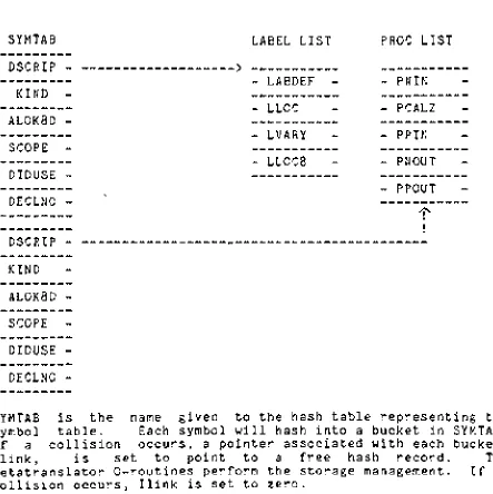
SYMTAB
DSCRIP
KIND
AL0K8D
SCOPE
DIDUSE
DECLNO
DSCRIP
KIND
AL0K8D
SCOPE
DIDUSE
DECLNO
LABEL
LIST
-
LABDEF
--
LLOC
-
LVARY
-
LL0C8
PROC
LIST
-
PNIN
--
PCALZ
--
PPIN
--
PNOUT
--
PPOUT
-^
SYMTAB
is
the
name givento
the
hash
table
representing
the
symbol
table.
Each
symbol willhash
into
abucket
in
SYMTAB.
If
a collisionoccurs,
a pointer associated with eachbucket,
Ilink,
is
setto
pointto
afree
hash
record.The
MetatranslatorQ-routines
performthe
storage management.If
nocollision
occurs,
Ilink
is
setto
zero.Each
hash
bucket
contains six attibutesthat
are commonto
all [image:14.552.48.467.160.397.2] [image:14.552.30.473.163.607.2]DSCRIP
This
is
a pointerthat
pointsto
a node
in
adescriptor
list
ALL0K8D
This
is
aflag
that
indicates
whether
the
symbolhas
been
allocated.It
is
setto
1
if
the
symbolhas
already
been
allocated,
otherwise0
SCOPE
This
explainsthe
scopefor
the
variable.
The
values are as 1follows:
1
External
symbol2
Local
symbol3
Global
symbol4
Entry
pointDIDUSE
This
is
aflag
that
is
1
if
the
symbol
has
been
usedin
aSYS-PROC,
otherwise0.
DECLNO
This
attributeis
usedfor
the
cross reference
table.
It
is
the
line
number on whichthe
symbol
is
declared.
KIND
This
attributeindicates
the
symbol
type
(variable,
label,
procedure,
etc.)After
the
symbolis
hashed
into
one ofthe
buckets,
a nodeis
allocated
in
the
descriptor
list.
DESCRIP
is
then
setto
pointto
that
nodein
the
list.
For
example,
a variable pointsto
anode
in
the
variablelist
and a procedure name pointsto
a nodein
the
procedurelist.
Although
the
node also pointsto
the
next node and
the
preceeding
node,
these
pointers are not used.Whenever
a nodeis
allocated,
the
storage managementQ-routines
automatically
allocateit
as a nodein
adoubly
linked
list.
However,
for
the
symboltable,
these
forward
andbackward
pointers are not necessary.
The
local
symbolsin
the
symboltable
are releasedby
returning
all ofthe
nodesin
the
linked
lists
back
to
the
storage pool.The
following
lists
are usedto
containdescriptor
information
LISTNAME
FUNCTION
VRBL
Variable
list
LABEL
Label
list
PROC
Procedure
list
FUNC
Function
list
TABLE
Table
list
FIELD
Field
list
EQUALS
Equals
tag
list
For
example,
the
procedurelist
containsthe
following
descriptors:
PNIN
Number
ofinput
parametersPCALZ
Flag
to
indicate
whetherthis
procedure calls another
procedure
PPIN
Pointer
to
input
parametersPNOUT
Number
of output parametersPPOUT
Pointer
to
output parametersAll
ofthe
data
structures usedin
pass1
are generated andmanipulated
by
the
Metalanguage.
Therefore,
the
stacks,
hash
tables,
andlinked
lists
in
the
first
passhave
been
defined
using
built-in
Metalanguage
declaratives.
There
are alsoMetalanguage
statementsthat
will add anddelete
items
from
linked
lists,
additems
to
hash
tables,
andtest
whether anitem
is
already
in
atable.
Other
data
structuresthat
pass1
utilizesinclude
stacksthat
are used
during
parsing
and ahash
table
calledRESERVED
that
PASS
1
LEXICAL
ANALYSIS
One
ofthe
functions
of alexical
analyzeris
to
readthe
source program charactersinto
abuffer.
The
Metatranslator
performsthis
actionthrough
variousQ-routines.
Qinput
readsin
the
characters and places
them
into
abuffer.
As
the
characters are readin,
Qconv
convertsthe
characters andintegers
into
the
internal
character-integer-code of
the
Metatranslator.
This
conversion
helps
to
preservethe
machineindependence
ofthe
first
pass.The
second role of alexical
analyzeris
to
partition aninput
string
into
a stream oflogical
units calledtokens.
Tokens
generally
include
items
such askeywords,
identifiers,
constants,
and punctuation symbols.The
Metatranslator
incorporates
lexical
analysisinto
the
syntactic analyzer.
One
caneasily
useBNF
to
describe
the
syntax of a symbol.
For
example,
the
following
defines
the
syntax of an
identifier.
<identifier>
::=<letter>
/
<identifier><letter>
/
<identifief><digit>
<letter>
::= a/
b
/
c/...z
<digit>
::=0/1/2/3/4/5/6/7/8/9
i
A
possibleMetalanguage
definition
for
anindentifier
is
asfollows:
$IDENTIFIER
. =1
TO
8
LETMERICS.
The
Metatranslator
has
reservedkeywords
that
represent various subsets ofthe
entire character set.Moreover,
these
keywords
are used
to
define
tokens.
.The
keywords
representthe
the
terminals
of a metalinguisticdefinition;
they
are shownbelow.
KEYWORD
TYPE
CHARACTER
TYPE
LETTER
DIGIT
ALMERIC
LETMERIC
1
2
3
4
A-Z
0-9
A-Z,
0-9
Letter,
letters
followed
by
digits
orSPACE
SPECIAL
NONQUOTE
5
6
7
space or
blank
only
OPERATOR
8
CHARACTER
9
NONSPACE
10
HEX
11
BINARY
12
OCTAL
13
arithmetic operators
(+,-,*,/,
AND
**)
all
all,- except space or
blank
0-9,
A-F
0
OR
1
0-7
The
Q-routine
Qterm
has
the
responsibilty
ofidentifying
terminals.
Suppose
the
following
metalinguisticdefinition
is
being
parsed:$INTEGER
.=1
TO
5
DIGITS.
In
this
case,
Qterm
"compares
each character underthe
cursorwith a
digit.
The
parse succeeds andthus
terminates
whenthe
maximum number of
digits
has
been
recognized.The
parsefails
if
the
minimum number ofdigits
is
not encountered.A
syntacticdefinition
may
alsoinclude
keywords.
For
example,
the
metalinguisticdefinition
of a goto statementmay
be
the
following:
$G0T0STMT
. =,'GOTO'^LABEL.
When
the
Metatranslator
generatesthe
parser,
the
keyword
enclosed
in
quotesis
placedinto
aliteral
table
calledQlvect.
When
the
parseris
parsing
a cardimage
andthe
presentmlv
is
a$G0T0STMT,
then
it
is
expectedto
recognize a 'GOTO'keyword.
Therefore,
each characterin
the
cardimage
is
compared with
the
'GOTO'in
the
literal
table.
If
they
areequal,
the
nextmlv,
$LABEL
,is
parsed.SYNTACTIC
ANALYSIS
The
intricate
mechanism ofparsing
is
best
described
by
an example.The
following
metalinguisticdefinitions
are similar$SIMPLESTMT
.=$GOTOPHRASE
,$EOL.
$GOTOPHRASE
.=GOTO' ,
$-NAME
,BEGIN
IF
$NAME
IN
SYMTAB,
BEGIN
IF
KIND
EQ
LABELK,
.L
IL(ILJ,KEYLAB,SYMPTR,
EJECT)
//
.LILULERR, 12, ERR, $NAME,
EJECT)
END
//
ETC...
END.
$EOL
.=CALL
CMS2EX,
CALL
MORE.
The
syntacticdefinition
statesthat
a simple statementis
composed of a goto phrase
followed
by
an end ofline
marker.A
goto phrase
is
composed ofthe
literal
'GOTO'followed
by
a name.If
the
nameis
in
the
symboltable
andkind
equalslabel
kind,
then
alink
is
establishedto
the
user-defined procedure calledIL.
The
first
referenceto
IL
links
IL
withthe
arguments of an unconditional
jump
quad.Otherwise,
link
to
IL
containing
the
arguments of an error quad.When
alink
to
adeferred
procedureis
established,
the
procedureis
notexecuted.
Instead,
its
arguments are stackedin
Qctab.
When
the
parsing
of$GOTOPHRASE
is
finished,
$EOL
is
then
parsed.This
mlv parses adollar
sign andthen
callsCMS2EX,
whichis
the
name ofthe
procedure executor generatedby
the
Metatranslator.
The
procedure executor executesthe
deferred
procedure
IL,
which unstacksthe
quad argumentsfrom
Qctab
and writesthem
outto
the
intermediate
language
file-
Next,
MORE
is
called which readsin
the
next cardimage.
v
Boolean
conditionalsin
CMS-2
are parsedin
the
most efficientmanner possible.
Let
Boolean
factors
be
defined
asitems
separated
by
OR's
andBoolean
term
be
items
separatedby
AND's.
If
any
ofthe
Boolean
factors
aretrue,
then
abranch
to
the
true
exitis
made withoutevaluating
the
otherBoolean
conditonals.
For
example,
supposethe
following
Boolean
expression
is
encountered:IF
V1
EQ
5
OR
V2
EQ
6
THEN
SET
V3
TO
V3+1
$
G4:
G5:
G1:
G2:
NE,V1,I5,G4
J,G1
NE,V2,I6,G5
J,G1
J,G2
+,V3,I1,T1SET,T1,V3
;IF
FALSE,
FALL
THROUGH
TO
NEXT
CONDITONAL
;OTHERWISE
JUMP
TO
TRUE
EXIT
;IF
FALSE,
FALL
THROUGH
TO
NEXT
CONDITIONAL
{OTHERWISE
JUMP
TO
TRUE
EXIT
;JUMP
END
OF
STATEMENT
;TRUE
EXIT
;END
OF
STATEMENT
If
the
conditional statementis
anif-then-else
construct,
then
the
jump
to
the
end ofthe
statementis
essentially
ajump
to
the
else portion.If
any
Boolean
terms
arefalse,
then
ajump
to
the
false
exitis
performed
immediately,
otherwisethe
nextBoolean
term
is
tested.
The
diagram
below
illustrates
the
shortcircuiting
ofBoolean
conditionals.The
diamonds
represent eachBoolean
Conditional
test
whilethe
straightline
downward
representsthe
shortest path.
OR
A
/
\
\
/
\/
j
A
/
\
\
/-\/
j
A
/
\
\
/-\/
tF
AND
A
/
\
\
/
\/
j
A
/
\
\
/-\/
iA
/
\
\
/-\/
;
T
The
problem withthis
methodis
that
it
generates goto's'togoto's.
For
Boolean
factors
the
algorithm generates conditonal quadsto
jump
to
the
next conditionaltest
and an unconditionaljump
quadto
exitearly
(for
Boolean
terms
it
is
the
otherway
around).
The
last
conditional quadjumps
to
alabel
whichthen
jumps
to
the
end ofthe
statement;
this
is
the
gototo
goto.The
gototo
goto codeis
optimizedduring
pass2.
column major
form.
The
basic
equation usedfor
array
referencing
given anarray
A(I,J,FLD)
is
asfollows:
base+(
(O*c+j)*r+i)*width+offset
wherebase
= address ofthe
array
c = number of columns
r = number of rows
width =
the
total
number of wordsfor
all ofthe
fields
offset =
the
number of wordsup
to
the
field
being
referencedSuppose
FOX
is
anarray
that
is
declared
withthe
dimensions3
by
4
by
2.
The
algorithm usedto
generate codeto
referenceF0X(1
,2,0,FOX2)is
asfollows:
1.
Push
on a stack a pointerto
each subscript.The
top
of
the
stack now pointsto
the
field
F0X2
whilethe
bottom
pointsto
the
1
.2.
Pop
the
stack sothat
the
pointerto
F0X2
is
in
a variable andthe
top
ofthe
stack pointsto
0.
3.
Generate
aSET
quadthat
places a0
into
atemporary
called
T1
.4.
Generate
a quadthat
multipliesT1
by
the
number of elements ofthe
dimension
pointedto
by
the
top
ofthe
stack,
storing
the
resultin
T1.
Add
the
subscript pointed
to
by
the
top
ofthe
stack and storethe
resultin
T1
.5.
Pop
the
stack.Repeat
step
4
untilthe
stackis
empty.
6.
Generate
a quadthat
multipliesthe
widthtimes
T1.
The
resultis
storedin
T1
.Add
the
offsetto
T1
andstore
the
resultin
T1
.The
generation^ of quadsfor
accessing
arrays storedin
columnorder
form
requiresthat
the
subscripts enterin
the
calculations
in
reverse order.Because
a parse scansfrom
left
to
right,
it
wasnecessary
to
stackthe
subcripts asdescribed.
Parameter
transmissionto
subroutines andfunctions
is
basically
a call
by
value withcopy
restore.Before
the
call,
quads are generatedthat
copy
the
argumentsinto
the
input
parameters andthe
call quadis
generated.If
the
item
being
calledis
aprocedure,
then
the
quads are generatedto
copy
the
output parametersinto
the
output arguments.For
example,
the
calling
sequencefor
a procedure calledPR0C(X,Y,Z)
withA,
B,
C
asSET
A,X
;COPYIN
FIRST
INPUT
PARAMETER
SET
B,Y
;COPYIN
SECOND
INPUT
PARAMETER
CALL.PROC
SET,Z,C
;COPYBACK
OUTPUT
PARAMETER
If
PROC
was afunction
calledPROCF,
then
the
calling
sequenceis
the
following:
SET
A,X
;COPYIN
FIRST
INPUT
PARAMETER
SET
B,Y
;COPYIN
SECOND
INPUT
PARAMETER
CALL
PROCF,
T1
If
the
function
returns a single precisionresult,
then
the
resultis
automatically
loaded
into
registerA.
If
it
is
adouble
precisionfunction,
then
register pairAB
is
used.The
temp
T1
indicates
atemporary
into
whichthe
result ofthe
function
may
be
storedif
there
is
no next use.It
is
also possibleto
pass arraysto
afunction
orprocedure;
this
is
achievedusing
callby
address.The
function
or procedureis
defined
using
CORAD(ITBL),
whereITBL
is
someindirect
table.
Indirect
tables
may
be
thought
of astemplates
which reserve no storage(except
the
double
wordcontaining
their
address).To
pass anarray,
a callis
performedusing
CORAD(TBL),
whereTBL
is
adirect
table
that
actually
exits.The
CORAD
intrinsic
function
passesthe
address ofthe
direct
table.
STORAGE
ALLOCATION
The
allocation of variablesis
termed
pass1.5
because
it
is
performed after
parsing
(pass
1)
andbefore
quadruple optimization(pass
2).
Moreover,
during
this
passassembly
language
necessary
for
allocation of variablesis
writtento
the
ASM
file.
The
codefor
this
passis
writtenin
the
Metalanguage.
A
mlv called$ALLOCATEGLOBAL
allocates all ofthe
global
variables,
which are containedin
aSYS-DD.
For
example,
suppose
the
variablesXYZ
andABC
werefound
in
aSYS-DD
calledGLOBAL.
Pass
1.5
would generatethe
following
assembly
Ncode:MODULE
GLOBAL
DSECT
ENTRY
ABC
ABC
RES
1
ENTRY
XYZ
XYZ
RES
END
1
All
global variables are allocatedin
a module withthe
samename as
the
systemdata
design.
The
ENTRY
assemblerdirective
definition
follows.
If
ABC
is
usedin
the
procedure,
then
it
is
declared
withthe
EXTERNAL
directive
indicating
that
it
is
anexternal variable
that
has
been
declared
elsewhere.The
mlv called$ALLOCATELOCAL
performsthe
allocation oflocal
variables.
If
aCMS-2
statementis
writtenin
whichtwo
local
variables are used
in
abinary
operation,
the
most efficientassembly
codeis
generated whenthe
two
variables are allocatednext
to
each otherin
storage.The
section on pass3
explainswhy
more optimal codeis
generatedin
this
case.Pass
1
keeps
adoubly
linked
list
calledINTEROP
which containspairs of
local
variablesthat
wouldbenefit
from
adjacency.The
list
starts out asthree
nodes,
which serve as markersfor
priority
levels.
!
0
!
0
|
.|
.|
HIGHEST
PRIORITY
<
(Insertions
for
highest
priority
nodes)!
0
!
0
|
.j
.|
HIGH
PRIORITY
<
(Insertions
for
high
priority
nodes)j
0
J
0
j
.|
.|
LOW
PRIORITY
<
(Insertions
for
low
priority
nodes)The
allocation schemeis
based
onthe
premisethat
the
variablesthat
are allocated atthe
beginning
ofthe
list
willhave
agreater chance of
being
nextto
each other.Therefore,
those
variables with a
high
priority
willbe
allocated atthe
head
ofthe
list
andthose
withlow
priority
willbe
allocated atthe
rear of
the
list.
The
highest
priority
is
assignedto
those
variable pairs
that
arein
avary
block
that
is
nestedinside
another
vary
block.
These
variables are aptto
be
usedthe
most often.High
priority
is
assignedto
variables within avary
block,
whilelow
priority
is
givento
variables not within avary
block.
When
a new set ofbinary
operatorsis
encountered,
the
variable components areinserted
into
the
list
according
to
their
priority
level
as shown.Suppose
variablesX1
throuth
X8
arelocal.
INTEROP
is
initially
set
to
(0
,0);
(0,0)
; (0
,0) ,which arethe
three
priority
levels.
If
X1+X7
is
found,
this
will resultin
INTEROP
being
(0,0);
(0,0);(0,0~);
(X1
,X7) .If
X1+X8
is
encounteredinside
aVARY
block,
it
is
added underthe
high
priority
level;
this
results with
INTEROP
=(0
,0); (0
,0)
;
(X1
,X8)
;
(0
,0)
;
(X1
,X7) .Suppose
after serveral moretrials,
INTEROP
is
equalto
(ignoring
the
zeroes)(X1
,X8);
(X1
,X3); (X1
,X7);
(X5
,X7) .adjacent allocation are separated
by
zeroes.MODEL
is
adoubly
linked
list
usedfor
the
final
sequencing
of.the
variables.Initially,
MODEL
=0,0.
Considering
the
first
pairin
INTEROP,
MODEL
=0,X1,X8,0.
The
second pair causesMODEL
to
be
0,X3,X1
,X8,0.The
third
pair cannotfit
into
the
model andis
therefore
ignored.
The
fourth
yieldsMODEL
=0,X3,X1
,X8,0,X5,X7,0.When
INTEROP
is
exhaused,
X2,X4,
andX6
are allocated
linearly,
thus
giving
the
order:X3
RES
1
X1
RES
1
X8
RES
1
X5
RES
1
X7
RES
1
X2
RES
1
X4
RES
1
X6
RES
1
Lastly,
-, pass1.5
writesthe
assembly
codeit
has
generateddirectly
to
the
assembly
language
file.
vCROSS
REFERENCE
TABLE
A
cross referencetable
is
generatedby
pass1
.The
crossreference
table
lists
global elements of a systemdata
design
and
the
local
elements of aSYS-PROC.
A
mlv called$CR0SSREF
generatesthe
cross referenceinformation.
The
format
ofthe
listing
is
asfollows:
NAME
KIND
TYPE
LINE
ADDR
Under
the
nameheading
lies
specifies
the
kind
ofdata
elemeinclude
PROC
(procedure),
EC
(variable),
TABLE,
FIELD,
OR
attributeindicates
the
type
of(integer),
R
(real),
A
(ar
(Boolean).
Line
indicates
,thdeclared.
Addr
indicates
the
element
is
avariable,
then
it
rDSECT.
If
it
is
a name enclosedto
the
name ofthe
table
that
the
is
**,
then
it
is
anindirect
the
namecolumn;
it
lists
the
scThe
keys
include
S
(global
scopeblank
indicates
local
scope.the
nnt
;
th
U
(eq
FUNC
variabithmet
eline
addres epresein
paitem
table.
ope qu),-N
(
ame of
the
e
followin
ualsdecl
(function
le
listed.
ic
fixed
on whichs of
the
ents
the
he
renthesis,
(a
field)
Another
alifier
fo
entry) ,
X
element
g
possib aration)).
Th
Type
c point) ,the
elemlement
.x
bias
f
then
it
belongs
.column
p
r each e(externa
.
Kind
lilites
,
VRBL
e
type
an
be
I
INTERMEDIATE
LANGUAGE
The
following
is
the
intermediate
language
generatedby
pass1
QUAD
MEANING
L
.ptrJ,OP1
JF,OP1
JT,OP1
SRC
COM
DIR
+.OP1 ,QP2,OP3 -,OP1 ,OP2,OP3*,OP1
,OP2,OP3/,OP1
,OP2,OP3OR,OP1
,OP2,OP3AND,0P1
,OP2,OP3XOR.OP1
,OP2,OP3EQV,OP1
,OP2,OP3SET,OP1
,0P2SHR,OP1
,OP2,OP3,OP4ABS,OP1
,0P2CALL,OP1
,0P2ENTER,
OP1
RETF,OP1
RETP
CORAD
ERR.OP1
,0P2EOF
-,OP1 ,OP2COMP,OP1
,0P2EQ.OP1
,OP2,OP3NE,OP1
,OP2,OP3GT,OP1
,OP2,OP3GE,OP1
,OP2,OP3LT,OP1
,OP2,OP3LE,OP1
,OP2,OP3G
.no .User
label
Jump
to
OP1
Jump
onfalse
to
OP1
Jump
ontrue
to
0P1
CMS-2
source statementComment
Direct
codeflag
0P3
<-0P1+0P2
0P3
<-0P1-0P2
0P3
<-0P1*0P2
0P3
<-0P1/0P2
0P3
<-0P1
.0R.0P20P3
<-0P1
.AND.0P20P3
<-0P1
.X0R.0P20P3
<-0P1
.EQV.0P20P2
<-0P1
Perform
atype
0P1
shift upon0P2
for
0P3
number oftimes.
The
destination
is
0P4.
0P2
<-ABS(0P1)
Call
procedure orfunction
0P1.
If
afunction,
resultis
left
in
0P2.
Entry
to
function
or procedureReturn
from
function;
the
returned valueis
left
in
0P1
.Return
from
procedureCall
to
CORAD
0P1
withseverity
level
0P2.
end of
file
flag
0P2
<- -(0P1)0P2
<-COMPLEMENT(OPI)
(
1
's complement)
IF
0P1
=0P2
GOTO
0P3
IF
0P1
j
=0P2
GOTO
0P3
IF
0P1
>
0P2
GOTO
0P3
IF
0P1
>
=0P2
GOTO
0P3
IF
0P1
<
0P2
GOTO
0P3
IF
0P1
<
=0P2
GOTO
0P3
NEVER
AGET,0P1
,OP2,OP3APUT,0P1
,OP2,OP3IGET,0P1
,OP2,OP3IPUT,0P1
,OP2,OP3T0AD,0P1
,OP2,OP3DEBUG,
0P1
KILL
Inaccessible
codeRead
from
anarray
0P3
<-0P2C0P1]
(0P2
IS
THE
SUBSCRIPT)
(Note:
there
is
nobase
registerin
the
476.
The
notationis
used
in
the
abstract sense.)Write
to
anarray
0P3L0P2]
<-0P1
(0P3
IS
THE
SUBSCRIPT)
Read
from
anindirect
array
Write
to
anindirect
array
Set
the
address of anindirect
array.Set
debug
flag
Generate
no codein
pass3
The
following
is
the
format
for
the
operandsin
the
intermediate
language:
!
TYPE
!
VALUE
!
Each
operandis
composed- oftwo
elements:
type
and value.The
value elementis
either aninteger
or real number.The
type
element
determines
the
meaning
ofthe
value element.The
eightdifferent
type
elements arelisted
below.
SYMBOL
I
R
V
T
L
F
P
G
ENUMERATION
VALUE
1
2
3
4
5
6
7
8
MEANING
OF
VALUE
INTEGER
REAL
NUMBER
POINTER
TO
VARIABLE
TEMPORARY
NUMBER
POINTER
TO
USER
LAEEL
POINTER
TO
FUNCTION
PASS
2
Pass
2
performstwo
basic
functions:
1
.Construction
of alabel
referencearray
2.
Machine
independent
optimizations upon quadruplesThe
label
referencearray
is
a onedimensional
Boolean
matrixwhich
is
initialized
to
all zeroes atthe
beginning
of pass2.
Each
position correspondsto
a compiler generatedlabel
number.When
a conditional or unconditionalbranch
quadis
encountered,
the
array
is
updated with a onein
the
location
corresponding
to
the
destination
ofthe
branch.
The
purpose ofthe
label
reference
array
is
to
inform
the
third
pass which compilerlabels
have
been
actually
referenced.This
table
is
necessary
because
optimizationduring
pass2
may
leave
afew
compilerlabels
that
are nolonger
needed.Two
types
of machineindependent
optimizations are performedin
pass
2.
The
first
is
termed
pinholeoptimization,
whichis
defined
asthe
transformation
ormapping
of a quadQ
into
anoptimized quad Q'
by
someoptimizing
function
F.
F
Q
--> Q'The
secondis
termed
peepholeoptimization,
in
whichtwo
or morequads are optimized at a
time.
PINHOLE
OPTIMIZATIONS
The
three
optimizing
functions
that
are usedfor
pinholeoptimizations
include
the
following:
1.
Logical
Simplification
2.
Algebraic
Simplification
3.
Optimal
Commuting
Table
2.1
illustrates
the
list
of pinhole optimizations used.TABLE
2.1
V
=ANY,
VARIABLE
T
=ANY
TEMPORARY
C
=ANY
CONSTANT(REAL
OR
INTEGER)
VAR
=VARIABLE
OR
TEMPORARY
INITIAL
QUAD
Logical
Simplification
GT,C,C
GT,C,C
LT,C,C
LT,C,C
LE,C,C
LE,C,C
GE,C,C
GE,C,C
EQ,C,C
EQ,C,C
NE,C,C
NE,C,C
AND,C,
OR,C,C
XOR,C,
COMP,C
,LABEL
,LABEL
,LABEL
,LABEL
.LABEL .LABEL ,LABEL
,LABEL
,LABEL
,LABEL
,LABEL
,LABEL
C,T
,TC,T
,TAlgebraic
Simplification
.O.VAR.T ,VAR,0,T ,VAR,0,T ,C,C,T ,.0,VAR,T ,VAR,0,T ,VAR,0,T,
VAR, VAR,
T
,C,C,T ,0,VAR,T ,VAR,0,T ,-1 ,VAR,T ,VAR,-1 ,T ,1 ,VAR,T ,1 ,VAR,T ,VAR,1 ,T ,VAR,1 ,T ,C,C,T ,VAR,1 ,T ,VAR,1 ,T ,VAR,-1 ,T ,0,VAR,T ,VAR,VAR,T
CCT
[var'con,t
SET,VAR,TOPTIMIZED
QUAD
DELETE
J,
LABEL
DELETE
J,
LABEL
DELETE
J,
LABEL
DELETE
J,
LABEL
DELETE
J,
LABEL
DELETE
J,
LABEL
SET, CON,
T
SET, CON,
T
SET, CON,
T
SET, CON,
T
DELETE
SET, VAR,
T
DELETE
SET,VAR,T
SET, CON,
T
-,VAR,T
DELETE
SET,VAR,T
SET,0,T
SET, CON,
T
SET,0,T
SET,0,T
-,VAR,T -,VAR,TDELETE
SET,VAR,T
DELETE
SET,VAR,T
SET,CON,.T
DELETE
SET,
VAR,
T
-,VAR,TSET,0,T
SET,1,T
SET, CON,
T
*,VAR,INV,T
DELETE
IF
C
NOT
>
C
IF
C
>
C
IF
C
NOT
<
C
IF
C
<
C
IF
C
NOT
<=C
IF
C
<=C
IF
C
NOT
>=C
IF
C
>=C
IF
C
!=C
IF
C
=C
IF
C
=C
IF
C
!=C
CON
=C
AND
C
CON
:C
OR
C
CON
=C
XOR
C
CON
=COMP(C)
IF
VAR
=T
IF
VAR
!=T
IF
VAR
=T
IF
VAR
!=T
CON
=C+C
IF
VAR
=T
IF
VAR
!=T
IF
VAR
=VAR
CON
=C-C
IF
VAR
=T
IF
VAR
!=T
IF
VAR
=T
IF
VAR
!=T
CON
=C*C
IF
VAR
=T
IF
VAR
!=T
IF
VAR
=VAR
Optimal
Commuting
LT, VAR,
CON
GT, VAR,
CON
LE, VAR,
CON
GE, VAR,
CON
EQ,
VAR,
CON
NE, VAR,
CON
,LABEL ,
LABEL
.LABEL.LABEL
,LABEL ,
LABEL
GT, CON, VAR,
LABEL
LT, CON, VAR,
LABEL
GE, CON, VAR,
LABEL
LE, CON, VAR,
LABEL
EQ, CON, VAR,
LABEL
NE, CON, VAR,
LABEL
Logical
simplificationtakes
advantage of compiletime
comparison and compile
time
logical
operations while algebraicsimplification utilizes compile
time
computations.Although
optimalcommuting
performedhere
may
notapply
to
somemachines other
than
the
476CX
microprocessor,
the
commuting
achieved
is
still machineindependent
in
the
sensethat
the
resultant quads are equivalent
to
the
originals.The
sequences of code shownbelow
illustrate
the
optimized codegenerated
by
the
476CX
after optimalcommuting
is
performed.EQ,V.01
,I.05,G5ADR
XYZ
LET
A
=RAM
ADR
KON+0
TEST
A+NOT
RAM
IF
-1 ,5SL5EQ,I.05,V.01
,G5LET
A==5
ADR
XYZ
TEST
A+NOT
RAM
IF
-1,
JBL5
During
codegeneration,
oneless
ADR
instruction
is
generated.Other
reasonswhy
optimalcommuting
wasincluded
in
pass2
withthe
other pinhole optimizationsinclude
the
following:
1.
It
was a one-quadtransformation,
the
requirementfor
apinhole optimization.
2.
This
optimization required no machinedependent
descriptors,
such as ' register or
RAM
descriptors
that
are neededin
pass3.
3.
This
optimization was easierto
implement
in
pass2.
The
pinhole optimizationin
whichdivison
by
a constantis
changed
to
multiplicationby
its
inverse
may
alsobe
considereda
borderline
machineindependent
optimization.The
justification
for
this
transformation
is
that
during
codegeneration,
division
involves
a callto
a single ordouble
precision externalroutine,
sincethe
476
possesses nohardware
divide
instruction.
Less
overheadis
involved
if
aharware
Pinhole
optimizations
are performedtwice
during
pass2.
This
optimization
is
accomplisheddirectly
afterthe
quads are readin
anddirectly
before
the
quads are written out.The
rationalebehind
this
is
that
constantfolding
may
resultin
a quadthat
can undergo
further
pinhole optimizations.All
optimizations
in
pass2
are performed within afive
quadwindow,
whichis
abuffer
that
possessesthe
capability
ofobserving
five
quads at atime.
The
data
structure ofthe
window
is
shownbelow:
LINK(5)
MATRIX(5,40)
3
2
1
5
4
The
link
array
contains a pointerto
each quadin
the
matrix array.Deletions
are performedby
updating
the
pointers andreading
a new recordinto
the
quadthat
wasjust
deleted.
The
data
structure usedfor
the
five
quadbuffer
is
essentially
an open ended
singly
linked
list
of quads.The
advantage ofusing
this
schemeis
that
deletion
ofany
quadmay
be
performedquickly
and easily.During
pinholeoptimization,
the
one quadtransformation
is
performed on
the
top
quad ofthe
window.The
remainder ofthis
sectioninvolves
abrief
description
ofthe
peephole optimizations performedduring
pass2.
Examples
are provided
to
show a sequence of quadsbefore
and afteroptimizaton .
TEMP
COMPRESSION
A
typical
block
of quads producedby
pass1
is
shownbelow:
*,V.05,V.22,T.01
*,V.06,V.13,T.02
+,T.02,T.01,T.03
SET,
T.
03,
V.
03
will ever
be
used again.Therefore,
the
result ofthe
additionoperation
in
the
third
quad canbe
assignedto
temporary
1
.+,T.02,T.01,T.03
>
+,T.02,T.01,T.01Since
temporary
3
is
usedin
the
fourth
quad,
it
also mustbe
changedto
temporary
1
to
reflectthe
initial
changeto
quad3-Temp
compression willtransform
the
aboveblock
of quads"into
the
following
block:
*,V.05,V.22,T.01
*,V.06,V.13,T.02
+,T.02,T.01,T.01
SET,
T. 01
,V.03Temp
compression reducesthe
number oftemporaries,
whichenables-
the
code generator
to
allocatethe
minimum number oftemporary
locations
for
aSYS-PROC.
Moreover,
more efficientassembly
codeis
generated.This
optimiztionis
performed onthe
first
and second quad ofthe
window.TEMP
COMMUTING
*,V.05,V.22,T.01
+.R.05.T.01 ,T.01
Temp
commuting
will commutethe
second quad asfollows:
*,V.05,V.22,T.01
+,T.01 ,R.05,T.01
When
codeis
generatedfor
a givenquad,
the
first
operandis
loaded
into
registerA
(single
precision) orAB
(double
precision) and
the
second operandis
addressed.Since
the
result of
the
arithmetic operation ofthe
first
quadis
left
in
register
A
orAB,
then
if
the
third
operand ofthe
first
quad equalsthe
first
operand ofthe
secondquad,
there
is
a next usein
regiserA
and a storeis
not necessary.The
temp
commuting
attemptsto
createthis
"next
use.CONSTANT
FOLDING
SET
A
T02*276/92*B
The
above equation would generatedthe
following
set of quads:*,
I.
02,
I.
276,
T.
01
/,T.01
,I.92,T.02*,T.02,V.07,T.03
SET,
T.
03,
V.
37
It
is
clearthat
the
first
two
quads couldbe
evaluated atdivision
for
the
first
two
quads and producethe
following
resulting
quads:*,I.06,V.07,T.03
SET,
T.
03,
V.
37
Constant
folding
is
performedby
using
atwo
dimensional
array
called
Tmptbl.
Each
column ofTmptbl
correspondsto
a