Commission of the European Communities
nuclear science
and technology
The Community's
research and development programme
on decommissioning of nuclear power plants
Commission of the European Communities
r science
echnology
The Community's
research and development programme
on decommissioning of nuclear power plants
Second annual progress report (year 1981)
Published by the
COMMISSION OF THE EUROPEAN COMMUNITIES Directorate-General
Information Market and Innovation Bâtiment Jean Monnet
LUXEMBOURG
LEGAL NOTICE
Neither the Commission of the European Communities nor any person acting on behalf of the Commission is responsible for the use which might
be made of the following information
Cataloguing data can be found at the end of this publication
Luxembourg, Office for Official Publications of the European Communities, 1983
© ECSC-EEC-EAEC, Brussels · Luxembourg, 1982
Printed in Belgium
CONTENTS
Page
FOREWORD 1
1. PROJECT N° 1: LONG-TERM INTEGRITY OF BUILDINGS AND SYSTEMS 3
1.1. Degradation of building plant and materials 3 1.2. Long-term integrity of buildings and systems 5 2. PROJECT N° 2: DECONTAMINATION FOR DECOMMISSIONING PURPOSES 7
2.1. Delegation of an expert to the USNRC in relation to the
cleanup of the TMI-2 plant 7 2.2. Decontamination of concrete surfaces by flame-scarfing 8
2.3. Erosion of metal surfaces by cavitation at very high
velocity 10 2.4. Composition of contamination layers and efficiency of
decontamination 14 2.5. Vigorous decontamination tests of steel samples in a special
test loop 15 2.6. Development of economic decontamination procedures 19
2.7. Development of gel-based decontaminants 21 2.8. Metal decontamination by chemical and electrochemical
methods and by water lance . 22 2.9. Economic assessment and decontamination for unrestricted
release 23
3. PROJECT N° 3 : DISMANTLING TECHNIQUES 26 3.1. Thermal and mechanical dismantling techniques 26
3.2. Plasma techniques for cutting mineral and metal materials .. 28
3.3. Diamond tipped saws for cutting concrete structures 29 3.4. Plasma-oxygen cutting of steel pressure vessels 31 3.5. Dismantling of concrete structures and metal components
using laser 32 3.6. Explosive demolition techniques for concrete structures .... 34
4. PROJECT N° 4: TREATMENT OF SPECIFIC WASTE MATERIALS: STEEL,
CONCRETE AND GRAPHITE 37 4.1. Assessment of management modes for graphite waste 37
4.2. Treatment of contaminated steel waste by melting 39 4.3. Immobilization of contamination on metals by coating with
thermosetting resins 41 4.4. Cobalt removal from steel by a smelting process of the
Electro-Slag Refining type 43 4.5. Treatment of concrete with silicate solutions to prevent
dusting 44 4.6. Coating of materials to protect against corrosion, fix
contamination and avoid powder formation 47
5. PROJECT N° 5: LARGE TRANSPORT CONTAINERS FOR RADIOACTIVE WASTE
PRODUCED IN THE DISMANTLING OF NUCLEAR POWER PLANTS 48 5.1. System of large transport containers for waste from
6. PROJECT N° 6: ESTIMATION OF THE QUANTITIES OF RADIOACTIVE WASTE ARISING FROM THE DECOMMISSIONING OF NUCLEAR POWER PLANTS IN THE
COMMUNITY 52 6.1. Activation products in the biological shield of the Lingen
reactor 52 6.2. Activation products in the biological shield of the KRB-A
reactor 54 6.3. Activation and radiation at the Garigliano pressure vessel.. 54
6.4. Trace element assessment of low alloy and stainless steels
with reference to gamma activity 55
7. PROJECT N° 7: INFLUENCE OF NUCLEAR POWER PLANT DESIGN FEATURES ON
DECOMMISSIONING 58 7.1. Catalogue of design features facilitating decommissioning of
AGRs 58 7.2. Design features of civil works of nuclear installations
facilitating their eventual refurbishing, renewal,
dismantling or demolition 59 7.3. Erosion-corrosion testing of cobalt-free materials to
substitute cobalt alloys 61 7.4. The control of cobalt and niobium content of reactor grade
steels 63 7.5. Removable coatings for the protection of concrete against
contamination 64 7.6. Characterisation and improvement of coatings protecting
concrete against contamination 65
8. IDENTIFICATION OF GUIDING PRINCIPLES 67
REFERENCES 68
ANNEX: MEMBERS OF THE ADVISORY COMMITTEE ON PROGRAMME MANAGEMENT IN
THE FIELD OF THE DECOMMISSIONING OF NUCLEAR POWER PLANTS 69
FOREWORD
This is the second progress report of the European Community's programme (1979-1983) of research on the decommissioning of nuclear power plants. It covers the year 1981 and follows the 1980 Report (Ref. 1).
The Council of the European Communities has adopted the programme in March 1979 (Ref. 2), considering:
"Certain parts of nuclear power plants inevitably become radioactive during operation; it is therefore essential to find effective solutions which are capable of ensuring the safety and protection of both mankind and the environment against the potential hazards involved in the decommissioning of these plants".
The programme seeks to promote a number of research and development projects as well as the identification of guiding principles. The projects concern the following subjects:
Project N° 1: Long-term integrity of buildings and systems; Project N° 2: Decontamination for decommissioning purposes; Project N° 3: Dismantling techniques;
Project N° 4: Treatment of specific waste materials: steel, concrete and graphite;
Project N° 5: Large transport containers for radioactive waste produced in the dismantling of nuclear power plants; Project N° 6: Estimation of the quantities of radioactive waste
arising from decommissioning of nuclear power plants in the Community;
Project N° 7: Influence of nuclear power plant design features on decommissioning.
The research is carried out by public organisations and private firms in the Community under cost-sharing contracts with the Commission of the European Communities. The Commission budget planned for this five-year programme amounts to 4.7 million ECU.
which consists of experts appointed by the Member States' governments and *
of Commission officials .
In the initial period of the programme, the work to be undertaken has been defined in detail and research proposals have been called for and carefully examined, project by project. Accordingly, the first Annual Report described the work programme of most research contracts relating to the Projects N° 1 to 4 and the orientation of the Projects N° 5 to 7.
The present report describes the work programme of further contracts awarded through 1981 most of them relating to the Projects N° 5 to 7 -and the progress -and initial results of the research relating to the Projects N° 1 to 5. The Commission staff in charge of the programme during
A*
1981 and of editing this report were: B. Huber , K.H. Schaller, R. Bisci and K. Pflugrad.
Finally, the Commission wishes to express its gratitude to all the scientists of the contractors who have contributed to this report.
B. Huber S. Orlowski Head of the Programme Head, Division
"Nuclear fuel cycle"
* See Annex
1. PROJECT N° 1; LONG-TERM INTEGRITY OF BUILDINGS AND SYSTEMS
It has been proposed that the dismantling of nuclear power plants be delayed for periods ranging from several decades to about a hundred years. Thereupon, radiation having largely died away, the dismantling would be easier and the radiation exposure of the dismantling workers would be less.
In this connection, measures are being studied to determine which ones are necessary to maintain retired plants in a safe condition over long periods. Particular attention is paid to the integrity of buildings and systems which contain the radioactive material (e.g. reactor building, reactor cooling system).
1.1. Degradation of Building Plant and Materials
Contractor: Central Electricity Generating Board, Barnwood, United Kingdom Contract N°: DE-A-001-UK Work Period: April 1980 - December 1983
1.1.1. Objective and Scope
The objective of this research is to establish the life cycle of existing nuclear power station buildings and ensure that specifications for new station buildings list materials that are suitable for a long life with minimum maintenance. Wherever possible, the research should aim at ensuring that the specified materials attract surface contamination only or induced activity which decays rapidly.
Long life maintenance treatment for retained plant and buildings for safety and security purposes will be researched, to enable future mainten-ance and surveillmainten-ance to be kept within reasonable economic limits. The types of nuclear power plants concerned by this research are Magnox reactors and Advanced Gas-cooled Reactors.
1.1.2. Work Programme: See Ref.l, Paragraph 1.1.2.
1.1.3. Progress and Results
1.1.3.1. Visits to and inspections of Magnox nuclear power stations
21 years. The objective has been to determine the required extent of repairs and renovations to ensure that plant and building integrity is maintained for both the expected remaining part of the station operational lives and for a further period of about ten years to cover defuelling and removal of reactor peripheral plant.
The results of these investigations indicate that built-up bitumi-nous felt roofing, coated metal wall cladding, metal wall louvres, sealing materials round doors, windows and wall penetrations and active drainage are areas where failure of materials has occurred, in some cases in a period as short as 14 years and, therefore, demand on-going maintenance for as long as these items are required to protect plant and services essential or useful to the decommissioning task.
1.1.3.2. Analysis of surveys on the condition of power station buildings Reports of surveys already made independently of this contract of the condition of buildings and structures at two nuclear and six coal-fired power stations, ranging in age from 15 to 28 years, are being studied and analysed. Although the contract research programme was origin-ally based on nuclear power stations only, it is considered sensible to make use of available information from conventional stations, particularly
those of greater age than the nuclear stations, since many constructional materials are common to both types and are in similarly exposed usage. This analysis has only recently commenced and the final results are not yet available, but problem areas identified, where material degradation has occurred, also include built-up bituminous felt roofing, roof asphalt,
coated metal wall cladding, metal window frames and structural steel framing where the protective coating has been inadequate.
1.2. Long-Term Integrity of Buildings and Systems
Contractor: Commissariat à l'Energie Atomique, Etablissement de la Vallée du Rhône, France
Contract N°: DE-A-002-F Work Period: January 1981 - December 1983
1.2.1. Objective and Scope
The aim of this study is to improve the knowledge of the aging of nuclear plant and to propose preventive measures for maintaining such plant in a satisfactory condition. The results should make it possible to choose the best decommissioning strategy (deferred or prompt dismantling) and to provide recommendations for the design of new plants.
It is planned to prepare a methodology document to be used for any nuclear power plant of which decommissioning is under consideration. This document has to deal with:
- identification of the plant components the safety barriers rely on, in case of Stage 1 (maintenance of the plant in a satisfactory condition) or Stage 2 (long-term containment) of decommissioning; - causes of aging and damaging effects, due to aggressive agents to
be considered depending on the nature of the components (concrete, steel...);
- measures to prevent or to cure these effects in order to maintain the plant in safe conditions at Stage 1 or Stage 2.
The results expected from this analysis are:
- elements for estimating the maintenance and surveillance cost; - elements for choosing the decommissioning stage and the delay
suitable to achieve Stage 3 (complete removal);
- information for the design of new plants, facilitating their future decommissioning.
1.2.2. Work Programme: See Ref.l, Paragraph 1.2.2.
1.2.3. Progress and Results
The reported work relates to a 900 MWe PWR plant as a reference.
1.2.3.1. Inventory of plant components
and/or the nature of the material i.e.: - concrete confinement;
- metal structures; - circuits and pipes;
- ancillary equipment (auxiliary systems, ventilation, electrical equipment).
A catalogue of the components and equipment which are to be main-tained, either in actual operation or in stand-by, has been prepared.
1.2.3.2. Study of aggressive agents
Using information collected through inquiries and literature re-search, the aggressive agents have been studied, in particular:
a) for concrete structures: weather conditions, i.e. temperature, humidity, salinity, wind, freeze/thaw cycles;
b) for metal structures: humidity, salinity, temperature, acidity, mechanical stress;
c) for electrical components (motors, power supply, relays...): mechanical stress (vibrations...), thermal and radiation stress. Items a) and b) are almost complete. A technical appendix has been devoted to the behaviour of ancillary equipment to be considered specifi-cally during Stage 1 or before reaching Stage 2.
1.2.3.3. Radiological aspects
Bibliographic data have been used to characterise the activity levels versus time, limiting this inventory to the identification of the causes of hazards to be considered:
- for accessibility of the components to be surveyed or maintained during Stage 1 or Stage 2;
- in case of failure of a safety barrier due to aging.
In order to confirm and complete the available data, information will be collected from measurements carried out in nuclear power plants during shutdown periods.
1.2.3.4. Preventive and curative measures
2. PROJECT N° 2: DECONTAMINATION FOR DECOMMISSIONING PURPOSES
In most of the radioactive parts of a nuclear power plant to be decommissioned, the radioactivity is present exclusively as surface conta-mination. Decontamination is aimed at simplifying the dismantling of these parts or reducing the arisings of the radioactive waste.
The following decontamination techniques are being assessed and developed:
- techniques using chemically aggressive liquid and gel-like decon-taminante;
- electrochemical techniques;
- hydromechanical techniques (high-pressure water lance, erosion by cavitation);
- decontamination of concrete walls by flame-scarfing.
Moreover, the composition and structure of the contamination layers, which are formed over a long operation period in the cooling circuit of
light water reactors, are being analysed.
The special decontamination problems which may arise after a reactor accident with loss of coolant are also being considered.
*
2.1. Delegation of an Expert to the USNRC in Relation to the Clean-up of the TMI-2 Plant
Contractor: Comitato Nazionale per l'Energia Nucleare, Rome, Italy Contract N°: DE-B-001-I Work Period: October 1980 - April 1981
2.1.1. Objective and Scope
The decommissioning of a nuclear power plant which has met with a major loss of coolant accident would need decontamination procedures different from those required in the case of a plant with a normal opera-tion history, because:
- the degree and the radioelement composition of the contamination are different;
- the activity may be spread over places which are normally not contaminated and where access is difficult;
- large quantities of radioactive liquids and gases must be treated.
The reactor N°2 of the Three Mile Island station (United States) offers valuable information on the contamination of a nuclear power plant which has met with an accident of this kind, and illustrates the problems encountered and the methods of decontamination used. The aim of this contract is to provide the Community with this information.
2.1.2. Work Programme: See Ref.l, Paragraph 2.1.2.
2.1.3. Progress and Results
The contractor had delegated an engineer to the USNRC to participate from October 1980 to April 1981 in the safety analysis of the clean-up operations proposed and performed by the owner of the TMI-2 plant. The delegate has reported on this assignment, covering mainly the following subjects:
- radioactive waste treatment (processing of released reactor coolant water, solidification of decontamination solutions);
- radioactive waste storage and shipment;
- radioactive discharges (essentially krypton-85); - occupational exposure;
- population exposure due to krypton-85 venting;
- surface decontamination (auxiliary and fuel handling building, reactor building);
- information obtained through containment entries (radiation levels, condition of equipment);
- risks of radioactive leakages to the underground water.
2.2. Decontamination of Concrete Surfaces by Flame-scarfing Contractor: Salzgitter A.G., Salzgitter, Germany
Contract N°: DE-B-002-D Work Period: October 1980 - June 1982
2.2.1. Objective and Scope
formation and filtering, radiological protection of the workers, feasibil ity of directly exhausting the combustion products to prevent recontamina tion, and magnitude of the decontamination factor.
'■·'.;
2.2.2. Work Programme: See Ref.l, Paragraph 2.2.2.
2.2.3. Progress and Results
2.2.3.1. Preliminary tests
Preliminary tests were made with a handheld multiplenozzle heating torch and propane gas, an oxyacetylene cutting torch, and a mechanically
operated flatsection torch with acetylene/oxygen supply. Torch form, gas
admission pressures and torch feed rates as a function of concrete compos ition have been optimised. The tests showed that best thermal input is
obtained using a flatsection jet torch.
2.2.3.2. Inactive tests on coated and uncoated concrete surfaces
Following the preliminary tests, flamescarfing was tested on bare
and coated concrete surfaces, in order to investigate whether the techni
que can be applied to coated surfaces. For this purpose, two nonradio
active specimen concrete plates (1 m χ 0.8 m χ 0.15 m square) were manu
factured according to the concrete specification for nuclear power plants 3
(density: 2.39 g/cm ) , and one of the plates was coated with epoxy resin
(film thickness about 0.1 mm).
Flamescarfing of the concrete surfaces was carried out in several
parallel strips using a flatsection jet torch of 100 mm width. An acety
leneoxygen mixture with a mix ratio of 1:1.25 was used as fuel gas. The
hand torch was manipulated by means of a remote-contr-Ί feeding unit. The
feed rate was set at a maximum of 0.5 m/min, which is the maximum rate possible without altering the equipment. The tests were carried out within an existing cabin that permits the arising dusts to be sucked off and determined quantitatively.
2.2.3.3. Results
and lies immediately below the coating was also removed at the same time. The cabin room air, however, was loaded with only a small part of the burnt-off material in form of aerosols. Most of the removed layer (approx. 1-2 mm) remained on the scarfed surface or fell down to the cabin floor. The quantity of the material dropped on the floor was not determined gravimetrically.
The aerosols arising during the flame scarfing tests were passed through an extraction duct without filtering, and isokinetic samples were taken and analysed. In addition, the dust resulting from subsequent treatment of the scarfed surfaces by brushing and grinding was sucked off with an EM 100 dust collecting probe (Messrs. Sartorius) in the form of isokinetic samples and subjected to a gravimetric analysis. The following values were obtained from an evaluation of the precision filters:
Test No. 1 2 3 4 Concrete finish bare bare coated coated Surface treatment flame-scarfing brushing, grinding flame-scarfing brushing, grinding Dust concentration (mg/m ) 26 165 22 144
2.2.3.4. Experimental work in preparation
Further tests will be conducted on coated and bare surfaces, to-gether with controlled filtering in the test plant's extraction duct of the aerosols arising from the flame-scarfing and during the subsequent treatment of the scarfed surface. Measurements of aerosnl retention by the filters will be done and the main process par'.uieters will be further optimised.
2.3. Erosion of Metal Surfaces by Cavitation at Very High Velocity Contractor: Alsthom-Atlantique Neyrtec, Grenoble, France
Contract N°: DE-B-003-F Work Period: October 1980 - September 1981
2.3.1. Objective and Scope
Cavitation is the formation of vapour cavities in zones of a flowing liquid where pressure is low due to high local velocity. Subsequently, the cavities collapse abruptly, and if this takes place near the surface of a
solid, the latter may be eroded.
The object of this research is to assess the feasibility of a surface erosion technique employing a cavitation flow of very high veloci-ty. A major advantage of such a technique, as compared with other deconta-mination techniques, would be to operate with pure water and, hence, to produce an effluent which can be treated easily, resulting in a small quantity of secondary radioactive waste.
2.3.2. Work Programme: See Ref. 1, Paragraph 2.3.2.
2.3.3. Progress and Results
2.3.3.1. Hydraulic design of the cavitation element
Using an experimental loop with a maximum flow-rate of 90 1/s at 6 bar, tests have been performed in order to optimise the geometry of the cavitation element.
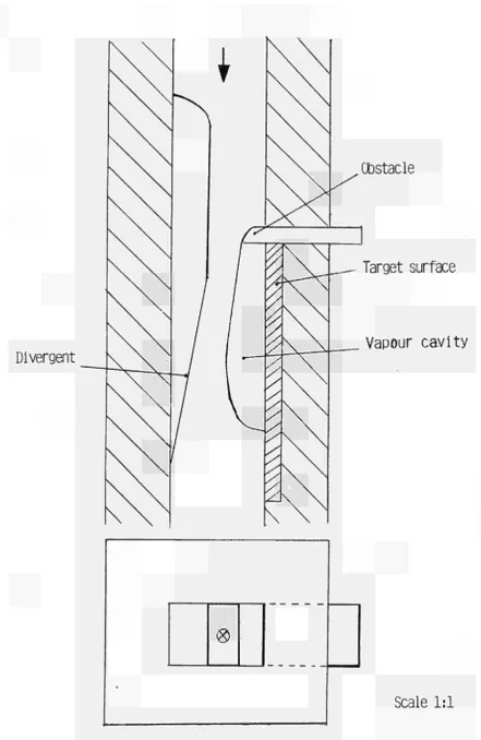
The chosen basic configuration of the cavitation element (see Figure 1) comprises a flow obstacle, for generating a large number of vapour cavities, and a wedge-shaped piece, creating a pressure increase, to produce abrupt collapse of the cavities. Compared with the characteristics considered for the real application of the technique, the dimensions of the cavitation element were four times larger and the flow velocity (20 m/s) correspondingly lower, so that hydraulic similarity (i.e. equal Reynolds number) was obtained.
Transparent walls of the test section enabled visualisation of the formation and collapse of vapour cavities, using fast-cinematography techniques. The impacts on the target wall produced by collapsing vapour cavities were recorded using high frequency acoustic sensors and an oscilloscope.
Divergent
Obstacle
Target surface
Vapour cavity
»
®
[image:18.595.54.496.57.736.2]Scale 1:1
Figure 1. Test section for hydraulic design of the cavitation element.
2.3.3.2. Erosion tests
Erosion tests have been performed with a pressure of 58 bar upstream the cavitation element which had a minimum flow section of 0.5 cm χ 1 cm. The flow rate was about 3 1/s, corresponding to a maximum flow velocity of 60 m/s. Since the characteristic dimensions of the cavitation element were half of those used in the low-pressure tests described in the previous paragraph, Reynolds numbers were in the same range.
Transparent side-walls of the test section enabled visualisation of the cavitation flow. The cavitation element was immerged in a water-filled tub and an adjustable slide plate was placed at the outlet of the cavita tion element to the tub. The slide plate made it possible to vary the outlet flow section and, thereby, the pressure in the zone of erosion.
Erosion tests made with aluminium alloy samples showed a decisive influence of the outlet flow section on the pattern of cavitation and 2 erosion. Maximum erosion was produced with an outlet section of 0.8 cm ; in this case, a short vapour pocket was formed behind the flow obstacle. After 8 h exposure to this type of cavitation, the volume of material
3
removed, as determined by surface profile measurements, was 1.2 mm . On an anodised aluminium sample treated for 1 h, the anodisation layer was
2 removed on an area of about 0.8 cm .
On a stainless steel sample treated for 1 h, a mark of very slight erosion was visible.
The tests have also shown erosion of the side-walls of the cavita tion element.
2.3.3.3. Extrapolation of the erosion tests
For extrapolation of the results of the erosion tests, it has been assumed,
- that the erosion rate increases with the sixth power of the flow velocity or, accordingly, with the third power of the pump press ure (at constant dimensions of the cavitation element);
- that the erosion rate is inversely proportional to the character-istical dimension of the cavitation element (at constant flow velocity);
Taking as a basis the erosion rate obtained on an aluminium alloy 3
sample (i.e. 1.2 mm in 8 h), it has been estimated that of the order of 2
1 m /h of surface could be cleaned (removal of 1 micron surface layer) with a pump pressure of 300 bar and a flow-rate of 7 1/s.
2.3.3.4. Proposal of further development
It is proposed to develop a new type of cavitation element, based on a circular geometry. The water would be supplied along the central axis, perpendicularly to the target surface and then be diverted to flow radial-ly outward, producing an annular zone of erosion. This geometry eliminates the side-walls of the cavitation stream and, thereby, the problem of their erosion and the associated energy loss.
The contractor has proposed a follow-up contract having as its subject the development of the new cavitation element.
2.4. Composition of Contamination Layers and Efficiency of Decontamination Contractor: Kernkraftwerk Lingen GmbH, Lingen, Germany
Contract N°: DE-B-004-D Work Period: January 1981 - June 1983
2.4.1. Objective and Scope
The purpose of this research is the characterisation of, on the one hand, the contamination layers formed in long-term reactor operation and, on the other hand, of the residual contamination after the application of aggressive chemical techniques. These investigations are performed on samples taken from the primary circuit of the Lingen reactor (520 MWth boiling water reactor shutdown in 1977 after nine years of operation).
2.4.2. Work Programme: See Ref. 1, Paragraph 2.4.2.
2.4.3. Progress and Results
2.4.3.1. Sample preparation and non-radioactive tests
At three locations of the primary reactor circuit, tube sections having carried steam, condensate and reactor water, respectively, have been cut out and segmented. The tube having carried reactor water showed a dose rate of 16 R/h measured at the outer surface.
Nonradioactive tests with an electrolytical method have been made in
order to determine the operational parameters for removing 1 micron of wall thickness at a time without a smoothing effect. With the
electro-lytical solution used and an optimum current of 4.2 A, 1 micron is removed 2
on an area of 100 cm in about three minutes. The removed thickness was measured using three different methods and good agreement was found.
2.4.3.2. Penetration measurements
The first measurements of the penetration depth of radioactive isotopes into the base material have been carried out on two tube samples from the steam system. After removal of the oxide deposit from the inner surface of the tube, the electrolytic removal of the base material took place in consecutive layers of 1 micron thickness. After removal of about
10 micron, the specific cobalt-60 activity changed only negligibly. This specific activity extends over the whole wall-thickness and originates probably from activation during reactor operation (see Figure 2).
2.4.3.3. Research on agressive chemical solutions
Preliminary tests have been made in order to determine a suitable pickling solution. Of the various pickling solutions tried out, only two (22% HCL + 5% HN0„ and 10% HCL + 1% H O ) produced satisfactory removal within 4 h.
2.5. Vigorous Decontamination Tests of Steel Samples in a Special Test Loop
Contractor: Ente Nazionale per l'Energia Elettrica, Rome, Italy
Contract N°: DE-B-005-I Work Period: October 1980 - September 1983
2.5.1. Objective and Scope
li
i
A Specific
cobalt-IO
1_
ié>
I O "
1.
activity (Bq/mg)
O) > o o
I ni
O Ü IH O
C o •H
4J
3 XI • H
w
0) α
• Η
4-1
Ι ctì
3
Safîple 1
Sanpie 2
CO Cl)
• H J 3
CN
from steam tube
from steam tube
Ufcfl ■ H Pu
Outer tube
wall surface
Removed layer jwn)
0
1
2
3
2.5.2. Work Programme: See Ref.l, Paragraph 2.5.2.
2.5.3. Progress and Results
2.5.3.1. Sample characterisation
Samples of contaminated material, mainly stainless steel, were taken from various locations of the primary circuit of the Garigliano reactor. The maximum dose rate was 4 rem/h, measured on the contaminated surface.
A preliminary characterisation of the contaminated oxide layers showed that the presence of magnetite, nickel ferrite and copper oxides can be related to the history of coolant water chemistry. Two periods were distinguished, according to the feed-water preheater materials, which had been copper-nickel alloy and Monel before 1968 and stainless steel after-wards. Correspondingly, the content of iron, copper and nickel in the primary coolant water had be.en much higher during the first period.
Radiometric measurements on some specimens of various primary tubing 2
showed surface contaminations of about 100 nCi/cm of gamma activity, 2
mainly due to cobalt-60, and about 5 nCi/cm of alpha activity, mainly due to plutonium-239 and americium-241 or plutonium-238, with traces of curium-244.
2.5.3.2. PECO loop
Design and assembling of the DECO loop have been completed and commissioning will be terminated by March 1982. The flow-sheet of the loop is shown in Figure 3.
2.5.3.3. Static decontamination tests
Static batch tests have been made, using the following hard etching solutions (with constant ionic strength):
a) 1.5% hydrofluoric acid + 15% nitric acid; b) 13.4% hydrochloric acid;
c) 4% hydrochloric acid + 13% nitric acid.
00
ρ-C
OJ
*1
I -1 o
1 co
π>
■Π)
r t
O
i-h
O M O O
O O
Venti l<* TO T5
P1 PRIMARY PUMP
P2 FEED EXCHANGER PUMP P3 FEED PUMP
P4 WASTE PUMP T1 EXPANSION TANK T2 FEED REAGENT TANK T3 FEED REAGENT TANK T4 FEED WATER TANK T5 SAFETY TANK
T6 NEUT. AND FLOC. TANK T7 GRAVITY WASTE TANK
T8 GRAVITY LIQUID WASTE TANK E1 PRIMARY HEAT EXCHANGER E2 SECONDARY EXCHANGER Β BOILER
rVTS TEST SECTION
EJ ION EXCHANGER V VALVE
VR REGULATION VALVE VNR CHECK VALVE PSV RELIEF VALVE ETV CENTRIFUGAL FAN FC CHEMICAL FILTER FA ABSOLUTE FILTER PI PRESSURE INDICATOR FI FLOW INDICATOR
Static decontamination tests were made with 1 litre of etching 2
solution and about 10 cm of contaminated surface. Very high decontamina-tion factors (greater than 1000) were obtained with soludecontamina-tions a) and b ) , resulting in residual contaminations comparable to ground level; however, the etching morphology was different: solution b) dissolved the oxide surface layer progressively, whereas solution a) caused a swelling-flaking of the oxide without dissolving the detached scales. The test temperature (30 to 80°C) appears to affect only the time required for oxide removal. Very low decontamination factors (lower than 2) were obtained with solu-tion c).
A test with 3 wt% oxalic acid + 3 wt% citric acid, ammonia buffered to 3.5 pH, at 80°C, showed incomplete oxide removal and a very low decon-tamination factor (1.3).
2.6. Development of Economic Decontamination Procedures
Contractor: Kernkraftwerk RWE-Bayernwerk GmbH, Gundremmingen, Germany Contract N°: DE-B-006-D Work Period: October 1980 - March 1983
2.6.1. Objective and Scope
The main objective of this research is to identify, develop and assess the most suitable decontamination procedures for decommissioning purposes with particular reference to BWRs. The work involves:
- supplementary contamination measurements, in addition to existing ones, in the KRB-A nuclear power plant (a 237 MWe BWR shut down in
1977 after 11 years of operation);
- decontamination experiments on samples taken from different areas of the primary circuit of the KRB-A reactor;
- evaluation of the experimental results in respect of both the KRB-A reactor and a 1200 MWe BWR.
2.6.2. Work Programme: See Ref. 1, Paragraph 2.6.2.
2.6.3. Progress and Results
2.6.3.1 Radiation levels in the plant
100 mrem/h inside the reactor.
2.6.3.2. Contamination layers on primary circuit pipes
Samples of horizontal ferritic steel pipes of 500 mm diameter of the condensate duct and of the steam duct of the primary circuit have been examined.
2 On the condensate pipe, an inner surface oxide layer of 100 mg/cm was found, with the following metal element contents: 70 wt% of iron, 0.6 wt% of copper and of nickel, 1.8 wt% of manganese and 0.2 wt% of chromium
2 and of cobalt. The contamination increased from the top (0.23 kBq/cm ) to
2
the bottom (0.73 kBq/cm ) of the pipe. The contribution of individual radionuclides to the total contamination varied with the location within the following ranges: cobalt-60: 16 to 55%; 134: 3 to 6%; cesium-137: 41 to 77%.
2
On the steam pipe, an oxide layer of about 1.6 mg/cm and contamina-2
tion of 17 kBq/cm were measured, except for a 10 cm large streak at the 2
bottom of the pipe, where a thicker oxide layer (22 mg/cm ) and higher 2
contamination (60 kBq/cm ) were found. This streak is probably due to the presence, during operation of the system, of a rill of water condensed from the saturated steam. Cobalt-60 accounts for 99% of the contamination of the steam pipe.
2.6.3.3. Decontamination tests
In preliminary screening experiments, 20 organic and inorganic acids have been tested on 4 cm χ 4 cm samples from the condensate duct. Tartaric acid and citric acid were found to be comparable to the best inorganic acids in decontamination efficiency and have, because of their unproblem-atic application, been selected for further studies.
The tests have shown that no further decontamination effect is achieved after lh of treatment. In order to reach the limit for un restricted release, the treatment has to be repeated using clean solu tions.
With an oxidation pretreatment (APAC type) and two consecutive treatments (3h, 92°C) with 5% tartaric acid, condensate samples have been
2
decontaminated from initial levels up to 1 kBq/cm to residual levels of 2
2 Bq/cm or less.
2.7. Development of Gelbased Decontaminants
Contractor: Commissariat à l'Energie Atomique, CEN Saclay, France
Contract N°: DEB007F Work Period: February 1981 September 1982
2.7.1. Objective and Scope
Existing decontamination techniques employ usually abundant quanti
ties of liquid decontaminant and, consequently, produce large volumes of
radioactive effluent. Less decontaminant is required, if the decontaminant
is applied by means of a gelatineous carrier substance.
The objective of this research is to develop a decontamination
technique using highly effective gelbased decontaminants, which is
capable of ensuring:
a reduction of the time during which personnel is exposed to
radiation;
a reduction of the contamination of a component, thereby enabling
it to be decontaminated more thoroughly after its transfer to the
decontamination bays;
the decontamination of vertical walls;
β. .reduction of the quantity of radioactive effluents resulting
from decontamination.
2.7.2. Work Programme: See Ref. 1, Paragraph 2.7.2.
2.7.3. Progress and Results
2.7.3.1. Preparation and characterisation of gels
Four gels, i.e. diopside gel, glycerophtalic gel, glycerophosphoric
gel and silica gel, have been selected as candidate carrier materials for
decontaminants. These gels have been produced in the laboratory and tested
with regard to viscosity and mass of gel adhering to a vertical stainless
steel surface, as a function of temperature (0 to 50°C) and of pH value.
The tests showed that the selected gels behave like a viscous liquid.
Nevertheless, their properties of adherence are much better than those of
aqueous solutions.
2.7.3.2. Preparation and characterisation of gels carrying decontaminants
and decontaminants have been studied:
- glycerophtalic gel as a carrier of sulfamic, oxalic, citric, tartaric and sulphuric acid and of a commercial detergent;
- glycerophosphoric gel as a carrier of phosphoric acid and of a commercial detergent containing phosphoric acid;
- silica gel as a carrier of sulphuric acid;
- diopside gel as a carrier of sodium hydroxide and potassium permanganate.
The products have been tested with regard to evolution of viscosity with time (checking on chemical stability), mass adhering to a vertical stainless steel surface and degreasing power. Good stability and high viscosity have been found. For application of the products by spraying, it would be necessary to reduce the viscosity. This could be achieved by
increasing the decontaminant content and/or the working temperature.
2.8. Metal Decontamination by Chemical and Electrochemical Methods and by Water Lance
Contractor: Commissariat à l'Energie Atomique, CEN Cadarache, France Contract N°: DE-B-008-F Work Period: January 1981 - December 1983
2.8.1. Objective and Scope
The aim of this research is to develop highly effective methods for the decontamination of steel for decommissioning purposes.
Chemical decontamination methods will be studied with the aim to provide very active scouring baths enabling the contaminated surface to be laid bare, without fears of corrosion damage. In order to limit the concentration of the chemicals employed, the chemical action will be accelerated or amplified by electrolytic action.
Decontamination by high-pressure (700 bars) water lance will also be studied, including the "hardening" of the liquid jet by the addition of solids (salts of low or slow solubility or inert abrasives) and the combination of chemical treatment and water lance.
The methods thus optimised will be evaluated with a view to their industrial application, taking into account, in particular, their effecti-veness, limitations, costs and radiological consequences.
2.8.2. Work Programme: See Ref. 1, Paragraph 2.8.2.
2.8.3. Progress and Results
Work during 1981 was concerned with chemical decontamination techni-ques.
Two types of stainless steel samples have been used in decontamina-tion tests, i.e.:
- samples contaminated with beta-gamma emitters (cesium-137, stront-ium-90, cobalt-60), taken from a shelf used in a hot cell;
- uranium contaminated samples, taken from a tub used in an enriched uranium treatment facility.
The samples have been pre-decontaminated by wiping with nitric acid and degreased with caustic soda (0.5h; 60°C). Subsequently, these samples have been used to test the efficiency of the decontaminants most currently used in the decontamination facilities of the Commissariat à l'Energie Atomique (27 different treatments). In parallel tests, the aggressivity of
the baths has been examined, using nonradioactive stainless steel samples (3 different grades) and determining the rate of thickness reduction and the evolution of surface roughness parameters.
Efficient decontamination of the uranium contaminated samples was easily achieved using moderately strong baths (i.e. oxalic acid + hydrogen peroxide, sodium bicarbonate + hydrogen peroxide, potassium disulphide). Decontamination of the samples contaminated with beta-gamma emitters required strong baths (i.e. hydrofluoric-nitric acid with or without oxalic acid). However, one type of moderately strong bath (sulfamic acid +
ferric sulphate) resulted also in good decontamination. With mechanically marked (cold-rolling) stainless steel, the use of strong baths (containing hydrofluoric acid) is necessary for obtaining good decontamination.
Moreover, the efficiency of various reagents towards magnetite was measured. Quick dissolution of magnetite was obtained either using oxalic acid at 80°C or, at room temperature, using hydrofluoric acid at pH close
to 3.
2.9. Economic Assessment of Decontamination for Unrestricted Release Contractor: Nuklear-Ingenieur-Service GmbH, Hanau, Germany
Contract N°: DE-B-009-D Work Period: February 1981 - March 1982
2.9.1. Objective and Scope
power plant components so that they can subsequently be released without restriction is needed as a basis for the further development and optimisa-tion of concepts for decommissioning. The objective of this study is to prepare such information, with due regard to existing national regulations on limit values for the unrestricted release of waste arising from decom-missioning operations and taking as a basis existing decontamination
techniques.
2.9.2. Work Programme: See Ref. 1, Paragraph 2.9.2.
2.9.3. Progress and Results
2.9.3.1. Regulatory aspects
Regulatory aspects have been investigated with co-operation of the Institut für Völkerrecht of the University of Göttingen. It appears that no regulatory criteria (i.e. residual activity limits and proving pro-cedures) for free disposal of large quantities of decontaminated material are existing in Community member countries.
2
Limit values of both 3.7 Bq/g and 0.37 Bq/cm have been assumed for the purpose of this study.
2.9.3.2. Classification of components
After classification of the components which are obviously deconta-minable (e.g. airborne contamination) or not decontadeconta-minable (e.g. activat-ed), the following aspects have been considered:
- occupational exposure; - costs;
- mass/surface ratio;
- geometry, in particular with regard to the possibility of measur-ing contamination;
- nature and level of contamination.
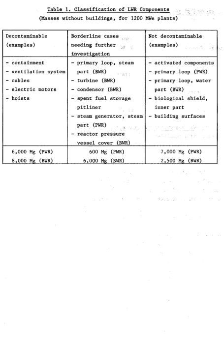
The classification drawn up so far is given in Table 1. The components listed as borderline cases will be further investigated. A particular difficulty lies in the scarcity of information on the quantities of secondary waste arising from strong decontamination methods.
Table 1. Classification of LWR Components (Masses without buildings, for 1200 MWe plants)
Decontaminable (examples)
- containment
- ventilation system - cables
- electric motors - hoists
6,000 Mg (PWR) 8,000 Mg (BWR)
Borderline cases needing further investigation
- primary loop, steam part (BWR)
- turbine (BWR) - condensor (BWR) - spent fuel storage
pitliner
- steam generator, steam part (PWR)
- reactor pressure vessel cover (BWR)
600 Mg (PWR) 6,000 Mg (BWR)
Not decontaminable (examples)
- activated components - primary loop (PWR) - primary loop, water
part (BWR)
- biological shield, inner part
- building surfaces
3. PROJECT N° 3: DISMANTLING TECHNIQUES
For the removal of a nuclear power plant, thick-walled steel compo-nents (e.g. reactor pressure vessel) and reinforced concrete structures
(e.g. reactor shielding) must be dismantled. Here, the radioactivity demands particular requirements such as remote operation, minimum dust formation and air cleaning.
The following techniques are being examined and developed:
- thermal techniques such as plasma-arc and oxygen cutting and cutting by laser beam;
- mechanical cutting techniques such as sawing;
- explosive techniques for the dismantling of concrete structures.
3.1. Thermal and Mechanical Dismantling Techniques Contractor: Transnuklear GmbH, Hanau, Germany
Contract N°: DE-C-001-D Work Period: March 1980 - June 1982
3.1.1. Objective and Scope
The purpose of this research is to try out various dismantling techniques on non-radioactive test specimens representative of components and structures of light water reactors and to evaluate these techniques as to performance, radiation exposure of personnel and environmental impact.
3.1.2. Work Programme: See Ref. 1, Paragraph 3.1.2.
3.1.3. Progress and Results
The thermal segmentation of heavy concrete and steel components by means of oxygen lances, powder cutting, oxyacetylene cutting, and plasma
cutting has been tested.
In order to gain experience in handling oxygen lances, and to determine the optimal burning parameters, cuts using 1/4", 3/8" and 1/2" lances were carried out on selected heavy concrete blocks. The oxygen consumption, lance wear, cutting speed, and the amount of slag deposit were measured in relation to the oxygen pressure of the various lance types. This revealed that for heavy concrete the 1/4" lance produces the best results. In particular, the amount of slag deposit (secondary waste) was negligible for this type of lance. This result shows that for cutting
concrete in nuclear power stations, the 1/4" lance is to be recommended. However, this type of lance showed less than satisfactory results for cutting steel.
During these tests the amount of dust produced, and the distribution of dust particle sizes were recorded. When designing filter installations with a view to using this process in the nuclear field, such knowledge is essential. In addition, these dust measurements enabled the suitability of the filtering systems used during the tests (cassette filters and particle suspension filters) to be assessed. When cutting concrete and steel compo-nents, the maximum particle size lies in the region of 0.3 micron, so that
for separation purposes only particle suspension filters can be used. When testing the powder cutting process, it was shown that it can only be used for splitting concrete structures if the wall thickness does not exceed 1000 mm and sufficient space exists where the slag deposits emerge. Comparable tests have proven that the powder cutting process gives better results than the oxygen lance and oxyacetylene cutting processes in respect to cutting rate and slag deposit.
Whereas the processes described so far are suitable for cutting con-crete and practically all types of steel, the use of the oxyacetylene cutting process is restricted to ferritic steels. The test results under-lined the known advantages of this process, such as its easy handling, little dust and slag deposit, low consumption of fuel gases, and negli-gible proneness to malfunction.
3.2. Plasma Techniques for Cutting Mineral and Metal Materials Contractor: Ansaldo Meccanica Nucleare, Genoa, Italy
Contract N°: DE-C-002-I Work Period: October 1980 - June 1983
3.2.1. Objective and Scope
This research relates to plasma-arc cutting and its basic aim is to provide more information on the process, to bring the various cutting techniques more closely into line, from a technical and economic stand-point, with the various possible applications in the dismantling of nuclear power plants, and to improve the safety and reliability of these techniques.
The plasma-arc cutting technique will be studied independently of the type of power station in which its use is envisaged; however, where specific examples have to be considered, the contractor will, as a licen-cee for Boiling Water Reactor stations, refer to this type of plant.
3.2.2. Work Programme: See Ref.l, Paragraph 3.2.2.
3.2.3. Progress and Results
After the bibliographic analysis, the evaluation of the various plasma cutting techniques has been completed. AMN, in cooperation with Messer Griesheim, analysed the actual possibility of using the plasma arc cutting technique in the decommissioning of a nuclear power plant and specified the R&D work necessary both in the field of control and in the field of cutting units and technology.
In these analyses, the Ansaldo/General Electric BWR/Mark II has been selected as a reference plant. The problems related to the application of the plasma cutting technique to this type of reactor have been analysed and a sequence in which plasma cuts mights be carried through during the dismounting of this reactor was tentatively defined.
Considering the problems revealed by this analysis, an experimental programme was planned with Messer Griesheim at the Hamburg University at the end of 1981. The scope of these tests was to optimise the cutting parameters (such as diameter of the plasma torch nozzle, distance between nozzle and workpiece, cutting speed, notching delay, voltage and current characteristics, gas flow rate, air flow) and the configuration of the cut and flash-line. The cutting tests were performed in an immersion basin
with two different types of plasma torch at water depths of 40 cm and 1 m respectively.
In the field of the thermo-lance cutting technique, after the bibliographic analysis and contacts with companies qualified in this technique, an agreement was reached with Fondibeton (Padova, Italy), to perform some tests with the thermo-lance. The size of the reinforced concrete specimens to be cut has been selected in order to represent typical reinforced concrete walls existing in the reference BWR plant. The test execution is scheduled in 1982.
In cooperation with CNEN, a programme to analyse the radiological protection and safety aspects of the cutting operations will be started in the first half of 1982. The plasma torch machine has already been placed at the CNEN Casaccia Centre and the equipment and instrumentation is going to be arranged.
3.3. Diamond Tipped Saws for Cutting Concrete Structures
Contractor: Central Electricity Generating Board, Barnwood, United Kingdom Contract N°: DE-C-003-UK Work Period: April 1980 - December 1983
3.3.1. Objective and Scope
The objective of this research is to develop a suitable diamond saw capable of cutting away remotely the inner 1 m activated layer of a rein-forced concrete biological shield or pre-stressed concrete pressure vessel. Since the dose rates within these structures will be too high to permit manual work for practical periods, the saw must be capable of being remotely controlled and operating reliably for long periods. In addition, the cooling system must be designed to be efficient but produce the minimum practical amount of slurry.
This research concerns all types of nuclear power plants.
3.3.2. Work Programme: See Ref. 1, Paragraph 3.3.2.
3.3.3. Progress and Results
The work carried out may be divided into: - visits to contractors and plant suppliers;
- demonstrations and field trials of saw machines;
saw unit.
At the outset of this contract a short literature survey was made of the use of concrete sawing in the civil engineering industry. Visits were paid to the principal saw blade manufacturers, in order to understand the technical processes and limitations in respect to high quality reinforced concrete, and to firms specialising in the use of sawing machines.
To establish the basis of the technology and to check claims about performance, the technique has been demonstrated on the turbine foundation blocks at an old coal fired station. Pieces of concrete 375 mm square section and 1 m long were removed from the face of a block in a manner that could be applied to an inner face of a biological shield.
The hydraulic powered wall saw comprised a manual/hydraulic propel-led carriage carrying retracting rollers, a heavy duty pivoting gearbox and a 20 kW hydraulic drive motor mounted on 3.5 m of track attached by stools to the face of the turbine block. During the trials, measurements were taken of cutting speeds, diamond segment wear, cooling water and electrical power consumption.
The sawing trial was completed successfully, but removal rates were much slower than expected. No serious dust, noise or vibration problems were encountered and cooling water supplies and electricity consumptions were reasonable. The lack of power in the power pack led to many adjust-ments being made to the cutting depth and speed of traverse of the saw.
From this first trial it was decided that development of a saw unit of sufficient power to cut to a depth of 1 m that could be controlled remotely would be justified. This conclusion was supported by the outcome of a second field trial carried out in March, which.demonstrated a 2.1 m diameter wall saw. This successfully made a number of cuts in a retaining wall at the now disused Swindon Power Station. The complete saw unit
comprised a diesel driven hydraulic power pack supplying a 35 kW hydraulic motor which was connected to the saw blade. The feed was adjusted manually and a small hydraulic motor drove the saw along a rack and pinion track securely attached to the wall. A cutting depth of 835 mm was achieved, but it was clear that if the method was to be applied to a reactor, modifica-tions to the carriage and blade cooling system would be necessary and the driving power would have to be increased.
In November 1981, work has been started to design and manufacture a large diamond tipped saw unit and power pack with associated controls. The
saw unit will be capable of being mounted on the jib head of a crane for vertical and horizontal cutting. The saw blade will be 2.5 m diameter and driven by a high torque slow speed axial piston swash plate motor of 75 kW rating. The saw carriage will be in the form of an oblong frame with two driving wheels corner mounted at one end and two castor wheels mounted centrally at the other end. As presently used in commercial operations, if a blade meets an obstruction, the overloading of the motor safeguards the saw blade, but with the uprating of the motor this protection of the blade is not available. Consequently, the relationship between the saw shaft power available and the load imposed by the saw traverse or feed is being designed to avoid saw blade damage. The testing of this saw unit should commence in April 1982.
3.4. Plasma-oxygen Cutting of Steel Pressure Vessels Contractor: Salzgitter AG, Salzgitter, Germany
Contract N°: DE-C-004-D Work Period: April 1980 -> September 1982
3.4.1. Objective and Scope
The purpose of this research is the development of a technique based on a combination of plasma and oxygen torches, capable of cutting up from the clad side thick sections of low-alloy steel clad with stainless steel, occuring in the pressure vessel of light water reactors.
The work comprises cutting tests on thick (up to 600 mm) inactive specimens, optimisation of cutting parameters and off-gas filtering system, and a concept study of dismantling reactor pressure vessels.
3.4.2. Work Programme: See Ref. 1, Paragraph 3.4.2.
3.4.3. Progress and Results
During 1980 the existing test stand had been adapted and several cutting tests were performed that the permitted initial statements to be made regarding the general applicability of the combination cutter. These tests showed that the high-melting oxides in the cladding detracted from the quality of the cut, but did not make cutting impossible.
steei grade St 37-2 (thicknesses: 150, 200, 250 and 300 mm) and the cladding was strips of plate of austenitic steel grade X 10 CrNiTi 18 9. (thickness: 10 mm).
Although, there was a large difference between the gas feed rates required in the various cutting series, due to the different cutting depths, combination cuts could be carried out at speeds of 40 to 180 mm/min, because the feed rate of the plasma torch could be set to match
that of the oxyacetylene torch without interrupting the arc of the plasma torch.
From the results obtained so far it appears that cuts up to 300 mm deep can be made in vertical and in horizontal position using a combined plasma-oxyacetylene cutting torch.
3.5. Dismantling of Concrete Structures and Metal Components Using Laser Contractor: FIAT TTG SpA, Torino
Contract N°: DE-C-005-I Work Period: April 1981 - December 1983
3.5.1. Objective and Scope
The aim of this research is to study laser techniques for the following applications in particular:
- drilling holes in prestressed and ordinary reinforced concrete for placing explosive charges with a view to demolition;
- cutting reinforced concrete structures;
- cutting thin and medium-thick metal components.
The laser cutting technique will be studied independently of the type of nuclear power station in which its use is envisaged; however, where specific examples have to be considered, the contractor will refer to stations incorporating Pressurized Water - Reactors and Gas-cooled Reactors.
3.5.2. Work Programme: See Ref. 1, Paragraph 3.5.2.
3.5.3. Progress and Results
The research carried out in 1981 consisted of a preliminary litera-ture search and specification, construction and testing of prototype equipment for the protection of mirrors and focusing optics from fumes and particles released in the laser cutting of steel and, more importantly,
concrete. This equipment was built and operated within the limitations imposed by the existing laser system.
The cutting tests were performed using the AVCO-Everett 15 kW carbon dioxide laser installed at the Centro Ricerche FIAT, Orbassano. The welding and cutting work station equipped with a comprehensive workpiece movement system, laser optics and beam focusing was used. A basic fume extraction system is installed.
The cutting technique is as follows. The laser beam interacts with the material surface to form a "key-hole" of molten metal whose depth is proportional to the applied power and the laser/material interaction time. When the beam is moved relatively to the material (or viceversa), the molten zone flows behind the initial "key-hole". If a suitable gas jet is directed onto this zone, the molten metal is expelled mechanically and vapour removal greatly facilitated. If the gas is also reactive, certain materials (mainly ferrous) initiate a violent exothermic reaction which increases the laser cutting ability due to the higher temperature produced and the more volatile reaction products which are easier eliminated. In thick sections, the cut surfaces deriving from the two reactions, i.e. laser melting and chemical reaction, are often distinguishable both in depth and appearance, depending on operating conditions. The laser reac-tion cut surface is normally smooth with slight and regularly spaced stripes, while the other surface is heavily ribbed and irregular.
In the course of these checks, using laser powers up to 14 kW, preliminary process parameter have been defined for selected materials. Steel sections up to 100 mm have been cut. The obtained results, apart form giving relationships between laser power, cutting velocity and material thickness, show that as the angle of incidence (respect to the vertical direction) of the assistant gas decreases towards 10°, cutting
efficiency rises. The cutting performance improves if the assistant gas pressure is risen to 6 or 7 atm, but falls back again at 10 atm (with 25 mm thick material).
Under the experimental conditions applied, the following preliminary conclusions can be drawn, which will be checked by more specific experi-ments in the next phase of this research:
- Beam focus: moving the beam from the material surface inward the material could allow a velocity increase of up to 20%.
a 10% average velocity increase.
- Material thickness: 1 mm increase in thickness corresponds to an average velocity decrease of 10%.
- Material composition: alloying elements have a marked negative influence on the velocity.
- Reactive assistant gas: the change from air to oxygen allows a large increase in cutting velocity. Assuming similarity between the steel grades UNI C 10 and Fe 42 C, speed increases up to 300% seem possible at 9.5 kW.
3.6. Explosive Demolition Techniques for Concrete Structures
Contractor: Taylor Woodrow Construction Ltd, Southall, United Kingdom Contract N°: DE-C-006-UK Work Period: January 1981 - December 1983
3.6.1. Objective and Scope
The objective of this research is to optimise and assess explosive techniques for the demolition of the radioactive concrete structures of nuclear power plants, in respect to safety, radiation protection and costs.
The research is directed mainly at the biological shields of early Magnox reactors and the prestressed concrete pressure vessels (PCPV) of later Magnox and Advanced Gas-cooled Reactors. Relevant structures of other commercial nuclear power plants in the European Community, in particular the PCPVs of French Gas Graphite Reactors and the biological shields of light water reactors, will also be considered.
3.6.2. Work Programme
3.6.2.1. General basic studies These studies include:
- literature study of present day demolition and quarrying tech-niques;
- studies of reactions which might be utilized in the demolition of reinforced concrete structures (e.g. stress wave focusing and reflection, chemical reactions);
- outline of the demolition relevant characteristics of the reference concrete structures considered, as defined under 3.6.1.
3.6.2.2. Assessment of model techniques
The validity of model techniques will be assessed together with a full dimensional analysis to determine where non-scaling effects may be important (about 6 tests).
3.6.2.3. Studies of explosive charge effects The following effects will be studied:
- size, placing and spacing of the explosive charges; - firing sequence;
- use of high or low explosives.
The best mechanism to induce maximum damage by material shattering or face spall will be assessed (about 15 demolition tests).
3.6.2.4. Studies of lined concrete structures
Steel-lined concrete structures will be studied to assess whether explosives may be used effectively to cut up the liner and the most efficacious way in which this can be achieved, e.g. by the use of liquid explosives filled in the cooling ducts of the liner (about 2 demolition tests).
3.6.2.5. Assessment of stress wave disintegration
The feasibility of stress wave disintegration will be assessed in-cluding studies of stress focussing. This assessment will be done mainly by computation, but includes about 2 demolition tests on concrete specimen of an appropriate size.
3.6.2.6. Studies of special effects
The following effects will be studied (about 12 demolition tests) : - various methods of tamping the, holes in which the explosive
charges are placed;
- shaped charge effects for stripping cover, cutting reinforcement and boring.
3.6.2.7. Experiments with simple models
1/4 of the real structures considered).
3.6.2.8. Experiments with closed ended cylinders
Experiments with closed ended hollow cylinders will be carried out to confirm that the techniques may be used with complete and monolithic structures (at least 1 model of an approximate scale of 1/4 of the real structures considered).
3.6.2.9. Studies of size effects with larger structures
Size effects are being studied in firings covered in Section 3.6.2.2. Firing under this section will be undertaken if a suitable existing structure is found and if planning permission for the test can be obtained.
3.6.2.10 Conclusive assessment
On the basis of the results of the preceding studies the explosive disassembly of the various structures considered, as defined under 3.6.1. will be tentatively assessed, including the necessary preparatory and com-plementary operations (e.g. liner removal, drilling of holes for explosive charges, disassembly of reinforced structures after shattering by explo-sive techniques, cutting of reinforcement bars, etc.). This assessment comprises:
- the description of the optimum procedures, considering the feasi-bility of successive dissassembly of active parts (i.e. the activated inner zone and contaminated surface layers) and inactive parts;
- discussion of explosive hazards;
- estimate of the radiation exposure of workers; - cost estimate;
- identification of uncertainties and gaps of information and of future work required.
During the tests, high-speed cine records will be taken as required and in some firings flash X-ray methods may be used. Following tests, detailed inspection and measurements of targets will be made to indicate crater size, etc. and, where appropriate, targets will be sectioned. Some stress wave sensors and crack indicators may be introduced in targets as appears necessary.
4. PROJECT N° 4: TREATMENT OF SPECIFIC WASTE MATERIALS: STEEL, CONCRETE AND GRAPHITE
In the dismantling of nuclear power plants, large amounts of radio-active steel, concrete and - in gas-cooled reactors - graphite will arise. This waste shall be volume reduced and suitably conditioned for disposal.
The following research works are being done:
- experiments on the melting of radioactive steel scrap including investigation of the possibility of decontaminating the melt;
- development and assessment of techniques for coating metal and concrete parts, in order to immobilise the radioactivity;
- comparative assessment of various modes of treatment and disposal of radioactive graphite.
4.1. Assessment of Management Modes for Graphite Waste
Contractor: National Radiological Protection Board in association with: Central Electricity Generating Board, United Kingdom Atomic Energy Authority and British Nuclear Fuels Ltd; United Kingdom
Contract N°: DE-D-001-UK Work Period: October 1980 - December 1981
4.1.1. Objective and Scope
The aim of this research is to yield more precise data on the radionuclide composition of the graphite waste arisings, to provide new information on the relative merits of a variety of disposal options, and to provide guidance on the selection of the most appropriate scheme. The disposal options examined are incineration, sea dumping and deep geologic disposal. An extension of the contract to include shallow land burial is being envisaged.
4.1.2. Work Programme: See Ref. 1, Paragraph 4.1.2.
4.1.3. Progress and Results
4.1.3.1. Activation product inventories
reactors and AGRs were calculated using the UKAEA reactor inventory code FISPIN. The predicted inventory of the 26 UK Magnox reactors is given in Table 2.
Table 2. Predicted radionuclide inventory (Bq) of graphite from decommis-sioning of the 26 UK Magnox reactors
(After 40 years reactor operation followed by 10 years decay)
3
H
10Be
14
c
3 6
ci
41Ca 54Mn 55Fe 59Ni
2.6
1.6
1.9
2.1
1.6
6.7
3.5
3.1
io
1 5io
1 2io
1 5io
1 3io
1 3io
9io
1 4io
1 260Co 63Ni 65Zn 93Mo 93mNb
94 Nb 99 Tc 108mA Ag
5.9
3.0
4.8
2.0
1.3
2.2
3.9
5.3
io
1 4io
1 410
9io
1 0io
1 010
5io
9io
1 11 1 3 m
cd
1 2 1 mSn 133Ba
Eu
Eu
Eu
2.4
1.0
1.3
2.6
1.1
3.5
io
1 1io
1 2io
1 3io
1 2io
1 4io
1 34.1.3.2. Engineering studies and cost estimates
BNFL has outlined a conceptual incinerator flowsheet. After hammer milling to pieces of about 2.5 cm size, the graphite is burnt with air at 1000°C. The off-gases are cooled with water spray to about 250°C and are then passed on to regenerable sintered stainless steel filters and, finally, to HEPA filters operating at 150°C. The ash (including spent filters) from 10 t of graphite, the daily throughput, is cemented into one 200 litre drum.
CEGB and UKAEA have studied concepts for the packaging and handling of irradiated graphite. The CEGB concept is based on the use of drums, in which case the use of returnable shielded overpacks appears attractive. The UKAEA concept is to incorporate graphite in a solid matrix within a reinforced concrete box of size 2 . 4 m x 2 . 2 m x 2 . 2 m .
Costs of the various operations have been estimated.
4.1.3.3. Radiological assessments
NRPB has carried out radiological assessments of the envisaged disposal options. Existing models have been adapted where necessary for use in this study, and data have been assembled on the environmental behaviour of activation product nuclides not previously modelled.