Commission of the European Communities
nuclear science
and technology
The Community's
research and development programme
on decommissioning of nuclear installations
Commission of the European Communities
nuclear science
and technology
The Community's
research and development programme
on decommissioning of nuclear installations
First annual progress report (year 1985)
Directorate-General
Science, Research and Development
Published by the
COMMISSION OF THE EUROPEAN COMMUNITIES Directorate-General
Telecommunications, Information Industries and Innovation Bâtiment Jean Monnet
LUXEMBOURG
LEGAL NOTICE
Neither the Commission of the European Communities nor any person acting on behalf of the Commission is responsible for the use which might be made of the
following information
Cataloguing data can be found at the end of this publication
Luxembourg: Office for Official Publications of the European Communities, 1986 ISBN 92-825-6599-8 Catalogue number*
© ECSC-EEC-EAEC, Brussels · Luxembourg, 1986
FOREWORD
This is the first Annual Progress Report of the European Community's 1984-88 programme of research on the decommissioning of nuclear installa-tions. It shows the status of implementation reached on 31 December 1985.
The Council of the European Communities adopted the programme in January 1984 /l/, considering: "Certain parts of nuclear installations inevitably become radioactive during operation; it is therefore essential to find effective solutions which are capable of ensuring the safety and protection of both mankind and the environment against the potential hazards involved in the decommissioning of these installations".
Also, the Council recognized that the 1979-83 programme of research on the decommissioning of nuclear power plants, of which the current pro-gramme is a follow-up, "has yielded positive results and opened up encouraging prospects". The main publications relating to the results of this first programme are listed in Annex I.
The 1984-88 programme has the following contents:
A. Research and development projects concerning the following subjects: Project No 1: Long-term integrity of building and systems;
Project No 2: Decontamination for decommissioning purposes; Project No 3: Dismantling techniques;
Project No 4: Treatment of specific waste materials: steel, concrete and graphite;
Project No 5: Large containers for radioactive waste produced in the dismantling of nuclear installations;
Project No 6: Estimation of the quantities of radioactive wastes arising from the decommissioning of nuclear installa-tions in the Community;
Project No 7: Influence of installation design features on decommis-sioning.
B. Identification of guiding principles, namely:
- certain guiding principles in the design and operation of nuclear installations with a view to simplifying their subsequent decommis-sioning,
- guiding principles in the decommissioning of nuclear installations which could form the initial elements of a Community policy in this field.
C Testing of new techniques under real conditions, within the framework of large-scale decommissioning operations undertaken in Member States.
The research is carried out by public organisations and private firms in the Community under cost-sharing contracts with the Commission of the European Communities. The Commission budget planned for this five-year programme amounts to 12.1 million ECU.
At the beginning of the 1984-88 programme, the Commission issued a
call for research proposals 111 with a first closing date of 9 May 1984,
and in 1985 it announced a second closing date (30 June 1985) , for
complementary proposals 131. Over 200 research proposals have been
received in total and only a fraction thereof could be accepted.
By 31 December 1985, 27 research contracts had been concluded - they form the subject of the present report - and 35 contracts were at the stage of negotiation. Progress achieved in 1984, the starting year of the programme, was not important enough to form the subject of a separate report and has, therefore, been included in the present report.
This first progress report, covering the period of putting the pro gramme into action, describes the work to be carried out under the 27 research contracts concluded, as well as initial work performed and first results obtained.
For each contract, the Paragraph "C. Progress of Work and Obtained Results" has been prepared by the contractor, under the responsibility of the Project Leader. The Commission wishes to express its gratitude to all scientists of the contractors who have contributed to this report.
The Commission staff having edited the report are: E. Skupinski, R. Bisci and K. Pflugrad.
Β. Huber
Head of the Programme
References
III Council Decision of 31 January 1984 adopting a research programme
concerning the decommissioning of nuclear installations. OJ N° L 36, 8.2.1984, p. 23.
IH Commission Communication concerning the research programme on the
decommissioning of nuclear installations (1984 to 1988). Call for research proposals. OJ N° C 68, 9.3.1984, p. 2.
131 Commission Communication concerning the research programme on the
decommissioning of nuclear installations (1984 to 1988). Closing date for research proposals. OJ N° C 101, 23.4.1985, p. 2.
CONTENTS
Page
1. PROJECT N° 1: LONG-TERM INTEGRITY OF BUILDINGS AND SYSTEMS 1
2. PROJECT N° 2: DECONTAMINATION FOR DECOMMISSIONING PURPOSES 2 2.1. Complete decontamination of a primary steam piping of the
Lingen BWR 3 2.2. Aggressive chemical decontamination tests on valves from the
Garigliano BWR 9 2.3. Decontamination using abrasives, electrolytical swab or jet,
chemical gels 14 2.4. Development of an easy-to-process electrolyte for
electro-polishing 19 2.5. Optimization of filtering systems for various concrete
decontamination techniques 24 2.6. Economic comparison of decontamination and direct melting
with a view to recycling of scrap 29
3. PROJECT N° 3: DISMANTLING TECHNIQUES 31 3.1. Ventilation and filtration techniques for thermal cutting
operations 32 3.2. Prefiltering devices for gaseous effluents from dismantling
operations 40 3.3. Dross and ultrafine particulate formation in underwater
plasma-arc cutting 46 3.4. In-situ arc-saw cutting of heat exchanger tubes and of pipes
from the inside 52 3.5. Electrochemical technique for the segmenting of activated
steel components 56 3.6. Explosive techniques for the dismantling of biological
shield structures 60 3.7. Prototype system for remote laser cutting of radioactive
structures 65
4. PROJECT N° 4: TREATMENT OF SPECIFIC WASTE MATERIALS: STEEL,
CONCRETE AND GRAPHITE 70 4.1. MeIting/refining of contaminated steel scrap from
decommissioning 71 4.2. Melting of radioactive metal scrap from nuclear
installations 78 4.3. Separation of stainless steel constituents using transport
in the vapour phase 81 4.4. Immobilization of contamination of large waste units by
polymer coating 85
5. PROJECT N° 5: LARGE TRANSPORT CONTAINERS FOR RADIOACTIVE WASTE
PRODUCED IN THE DISMANTLING OF NUCLEAR INSTALLATIONS 90
-6. PROJECT N° 6: ESTIMATION OF THE QUANTITIES OF RADIOACTIVE WASTE ARISING FROM THE DECOMMISSIONING OF NUCLEAR INSTALLATIONS IN THE
COMMUNITY 91 6.1. Computer programs for the measurement of low-level gamma
contamination 92 6.2. Methods to establish the curie content of waste from
decommissioning ·... 96 6.3. Systems for contamination measurements on curved surfaces...100
7. PROJECT N° 7: INFLUENCE OF NUCLEAR INSTALLATION DESIGN FEATURES ON
DECOMMISSIONING 103 7.1. Decontamination and remote dismantling tests in the ITREC
reprocessing pilot plant 104
8. SECTION C: TESTING OF NEW TECHNIQUES UNDER REAL CONDITIONS 107 8.1. Dismantling and decontamination of a feedwater preheater
tube bundle of Garigliano BWR 108 8.2. Conditioning, transport and dismantling of very large
plutonium glove-boxes 114 8.3. Large-scale application of segmenting and decontamination
techniques 120 8.4. Development of techniques to dispose of the Windscale AGR
heat exchangers 126 8.5. Pilot decommissioning of a mixed-oxide fuel fabrication
facility 129 8.6. Testing of new techniques in decommissioning of a fuel
(U, Th) fabrication plant 133
X X
X
ANNEX I LIST OF PUBLICATIONS RELATING TO THE RESULTS OF THE 1979-83 PROGRAMME ON THE DECOMMISSIONING OF NUCLEAR
POWER PLANTS 136
ANNEX II MEMBERS OF THE ADVISORY COMMITTEE ON PROGRAMME MANAGEMENT IN THE FIELD OF THE DECOMMISSIONING OF NUCLEAR
POWER PLANTS 139
ANNEX III MEMBERS OF THE MANAGEMENT AND COORDINATION ADVISORY
COMMITTEE "NUCLEAR FISSION ENERGY - FUEL CYCLE/PROCESSING
AND STORAGE OF WASTE" 140
-1. PROJECT N°l:
LONG-TERM INTEGRITY OF BUILDINGS AND SYSTEMS
A. Objective
It has been proposed that the dismantling of nuclear installations be delayed for periods ranging from several decades to about a hundred years. Thereupon, the radioactivity having largely died away, dismantling would be easier and the radiation exposure of the dismantling personnel would be less. The objective of this project is to determine the measures required for maintaining shut-down plants in a safe condition and to assess the radiological consequences and costs.
B. Research performed under the 1979-83 programme
The work performed under the previous programme relates mainly to the following aspects:
- mode and pace of degradation of various materials as they exist 'in nuclear power plants;
- measures for maintaining plants in a safe condition and for keeping the necessary ancillary systems operable;
- monitoring and inspection procedures;
- radiological consequences and costs of maintaining the plants.
C. 1984-88 programme
The work performed under the first five-year programme should be comple-mented by further tests and the study of control methods relating to the aging of relevant plant materials and by exploitation of additional experience with shut-down nuclear installations.
D. Programme implementation
At the end of 1985, three research contracts relating to Project N°l were at the stage of negotiation.
2. PROJECT N°2:
DECONTAMINATION FOR DECOMMISSIONING PURPOSES
A. Objective
The objective of this project is to develop and assess techniques for decontaminating surfaces of components and structures of nuclear instal-lations that are past use. The main purpose of decontamination would be reduction of the occupational radiation exposure during dismantling of the contaminated item and/or reduction of the volume of radioactive waste.
B. Research performed under the 1979-83 programme
The following decontamination techniques have been developed and asses-sed:
- techniques based on the use of chemically aggressive decontaminante In liquid and gel-like form;
- electrochemical techniques;
- hydromechanical techniques (high-pressure water lance, erosion by cavitation);
- decontamination of concrete walls by flame spraying.
Other activities were:
- investigation of the characteristics and distribution of contamination in nuclear power plants that are past use;
economic assessment of decontamination for unrestricted release;
collection of information on the particular decontamination problems posed by accidental contamination, as in the case of the TMI-2 nuclear power plant.
C. 1984-88 programme
Selected aggressive decontamination methods should be further developed with a view to their industrial application. Increased effort should be paid to the conditioning of spent decontaminants, where suitable techni-ques do not yet exist, and to the reduction of secondary waste arisings. Physical methods that limit the production of liquid effluents might be considered.
An important new topic of the second programme would be the decontamina-tion of hot cells and equipment contaminated with plutonium and other transuranics for purposes of the decommissioning of fuel-cycle installa-tions. The specific features of such installations (chemical nature of the liquids used during their operation, dimensions of the components, etc.) would be taken into account.
D. Programme implementation
At the end of 1985, six research contracts were at the stage of execu-tion, and three contracts were at the stage of negotiation.
2.1. Complete Decontamination of a Primary Steam Piping of the Lingen BWR
Contractor: Kernkraftwerk Lingen GmbH, Lingen, Germany Contract N": FIlD-OOOl
Working Period: January 1985 - March 1986 Project Leader: W. Ahlfänger
A. Objectives and Scope
A foregoing research contract (DE-B-004-D), aimed at the investiga-tion of the composiinvestiga-tion of contaminainvestiga-tion layers and of the effectiveness of possible decontamination procedures of primary circuit steam lines, was concluded by following main results:
the surface contamination is to an extent of 99% of oxide composition, the remainder is located at a penetration depth of up to 90 um in the base material. For a successful decontamination, it is necessary to dissolve, besides the oxide layer deposited on the surface, also a small layer of the base material;
- the best way of decontamination (using solutions with less than 2% concentration) is to strip the deposited oxide 'layer by a LOMI react-ive and a part of the base material by a mixture of hydrochloric and nitric acid.
These results have been obtained by laboratory-scale tests on representative samples.
The objective of this research contract is to demonstrate that the above decontamination procedure is also appropriate for a large-scale application to a steam line of the Lingen Nuclear Power Station.
B. Work Programme
B.1. Manufacturing of the decontamination rig comprising the sample steam pipe and all needed components for decontamination.
Preliminary laboratory decontamination tests of representative samples including determination of the composition and activity level of the contaminated layer.
Main test programme using the decontamination rig.
Assessment on optimal treatment of the generated radioactive secon-dary waste.
Evaluation of experimental results with respect to man-dose, quanti-ties of secondary waste and cost analyses, with extrapolation to a 1200 MWe BWR.
B.
B. B. B.
, 2 .
. 3 . .4. .5.
C. Progress of Work and Obtained Results
Summary ,
An average value of 3.1 χ 10 Bq/cm2 for the surface activity (Co-60) of
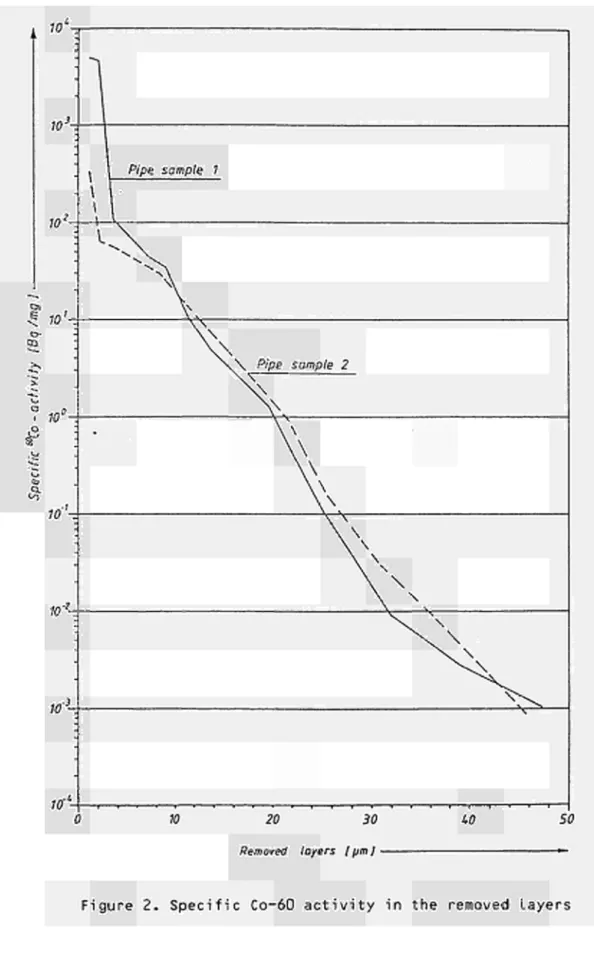
the primary steam line resulted from the studies. As shown by the results of the depth profile.measurement, the Co-60 content in the base material amounts to < 4 χ 10 Bq/mg concerning a layer of 40 um. The lowering of the pH value to 2.5 concerning the LOMI treatment steps was an essential change with respect to the different chemical treatment solutions. By doing this, the loosening of the oxidic layers could be clearly Improved. After the completion of the process, the residual activity (Co-60) amounted to 0.33 Bq/cm2.
Progress and Results
1. Set-up of the decontamination circuit (B.l.)
A pipeline piece was separated from the remaining system for the deconta mination test and bound into a decontamination circuit with pump, buffer container etc. (Fig. 1).
2. Pre-examinations in the laboratory (B.2.)
As was shown by the pre-examinations, the concentrations of the oxidation and oxalic acid solutions could be reduced by a factor of 4 without a deterioration of the decontamination effect. The examination was of special importance as the removal of the oxidic layers could be clearly improved by the lowering of the pH value to 2.5 with respect to the LOMI reagent. The results from the studies concerning the Initial surface activity (Co-60) showed different activity values:
6.1 χ 103 to 5 χ 104 Bq/cm2.
From the activities removed by the decontamination, an average surface activity of
3.1 χ 104 Bq/cm2
was calculated.
The results of the depth profile measurement are shown in Fig. 2.
3. Execution of the decontamination (B.3.)
The entire process course and the decontamination effect of the indivi dual treatment steps are summarized in tables I to III. The following particularities were remarked:
- Contrary to the observations during the laboratory tests, pit corro sion was clearly noted after the first acid treatment.
- The Cr_0_ layer, precipitated during the acid treatment with the also precipitated activities, was not sufficiently removed by the subse quent treatments with the oxidation and oxalic acid solution, so that activity was carried into the next treatment step. This is shown by the too high surface activities of the pipe samples f and g compared to the activities measured in the base material in these layers
(Fig. 2).
After the last treatment step, the residual activity (Co-60) amounted to 0.33 Bq/cm2 and was therefore smaller than the limit for unrestricted
release (0.37 Bq/cm2).
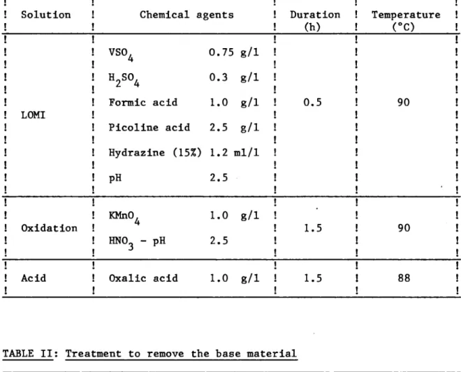
-TABLE I; Treatment to remove the oxide layer ! Solution ! LOMI ! Oxidation ! Acid Chemical agents
VSO. 4
H2S04
Formic acid
Picoline acid
Hydrazine (15%)
PH
KMnO, 4
HN03 - pH
Oxalic acid 0.75 0.3 1.0 2.5 1.2 2.5 1.0 2.5 1.0 8/1 8/1 8/1 8/1 ml/1 8/1 8/1 Duration (h) 0.5 1.5 1.5 Temperature ! (°C) ! 90 ! | 90 ! 88 !
TABLE II: Treatment to remove the base material
! Treatment ! 1 ! 2 ! 3 ! 4 !
! Acid I ! ! ! ! ! HCl g/l Í 13 ! 22 ! 6.5 ! ! ! HNO g/1 ! 4.7 ί 4.7 ! 2.35! ! ! duration h ! 6 . 5 ! 7 ! 8 ! ! ! temperature °C ! 60 ! 60 ! 60 ! ! ! dissolved material (Fe) g ! 552 ! 592 ! 194 ! ! ! removed layer um ! 15.3 ! 16.4 ! 5.4 ! !
! Oxidation ! ! ! ! ! ! KMNO, g/1 ! 0.5 ! 1 ! 1 ! 2 ! ! NaOH g/1 ! 0.5 ! 0.5 ! 0.5 ! 2 ! ! duration h ! 2 ! 2 ! 2 ! 2 ! ! temperature °C ! 90 ! 90 ! 90 ! 95 !
TABLE III: Decontamination course
! !
! Treatement steps
!
1
!
! Before treatment
! Removal of the oxide layer ! LOMI-solution
! oxidation solution ! oxalic acid solution !
! Removal from the base ! material
! 1. acid treatment ! acid solution ! oxidation solution ! oxalic acid solution
! 2. acid treatment ! acid solution ! oxidation solution ! oxalic acid solution
! 3. acid treatment ! acid solution ! oxidation solution ! oxalic acid solution
! 4. subsequent solution ! oxidation solution ! oxalic acid solution
Dissolved activity (Bq: 2.0 3.1 4.1 7.4 1.8 1.4 2.1 1.2 1.0 1.9 3.4 3.3 6.5 X X X X X X X X X X X X X 108 108
io
8 106 106 10» < 104 Activity determined by electrolitic removal (Bq/cm2)N¡-dosage ^ ^ NW ÍO
cooling
thermostat
heating
NW50
evacuation (sampling!
Addition of chemicals lem
i
w >■
NW 25
NW SO
N, waste air plant
-Ni- sampling
K5
i
N f rinsing coni a in er
evacuation (sampling)
Ρ Pressure Measuring Place
-Q-Sm'/h
τ
NW2S
NW IO sampling
-iXh
l
X
> bypassOperating Pipe Line
sampling point of the pipe sample
Removed layers
2.2. Hard Chemical Decontamination Tests on Valves and Treatment of the Waste Arising from the Process
Contractor: Ente Nazionale per l'Energia Elettrica, Roma, Italy Contract N°: FI1D-0002
Working Period: January 1985 - December 1986 Project Leader: F. Bregani
A. Objectives and Scope
The aggressive chemical decontamination methods, whose effectiveness has been proved both in many laboratory tests and in pre-industrial applications, appear to need further investigations regarding both the decontamination of complex systems, such as valves, and spent decontami-nant treatment in view of the limitation of the secondary wastes aris-ings.
The scope of the research is both to check the effectiveness of hard chemical decontamination on used components, such as small valves, and to search and develop a suitable and safe procedure to treat spent solu-tions, arising from aggressive chemical decontamination.
The advantages of this research are the possible demonstration of the decontamination effectiveness on complex components and the minimiza-tion of the total wastes produced.
This proposed research will be carried out in collaboration with CISE in the framework of a specific multi-annual agreement already in force. The experiments will be performed in DECO laboratory at Ispra, JRC.
Regarding the application of chitosan, specific agreements with the University of Ancona have already been undertaken.
B. Work Programme
B.l. Hard chemical decontamination tests on valves (2-3 inches), of the primary cooling system of the Garigliano BWR in DECO loop.
B.2. Identification and qualification of a simple procedure to condition the spent decontaminant.
B.3. Neutralization and flocculation tests in order to select and evalu-ate the best neutralizing agent and specific chemical agents, such as chitosan, as supporter in flocculation.
C. Progress of work and obtained results Summary
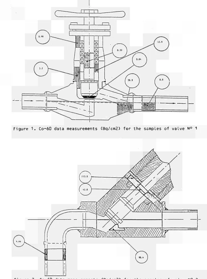
The results of two decontamination tests of small valves from the primary system of the Garigliano power station are reported.
The valves are in stainless steel base material and have been in operation for about fifteen years in high temperature and high pressure BWR condi tions .
The runs were performed in the DECO experimental loop. The first run used a hydrochloric solution (4.1%) while the second one was carried out with a hydrofluoric and nitric mixture (1.5% + 5%). Many measurements on the valves after decontamination in order, to discover the exact localization of the residual radioactivity, were performed. To a first approximation, the results show that the hard chemical decontamination, to ensure total cleaning of all the internal surfaces,is very difficult; traces of residual contamination remain in some particular areas such as crevices, welds, dead zones, etc.
Preliminary tests about the treatment of the hard chemical decontaminant by flocculation and neutralization were performed too.
Progress and results 1. Introduction
Following the experimental studies performed in the period from. October 1980 to September 1983 on the chemical decontamination with highly aggressive solution /l/, ENEL-CRTN is continuing with the activity in this field.
In particular, as part of a qualification programme in hard chemical decontamination, some small valves from the Garigliano power plant are testing in the DECO experimental loop at JRC-Ispra. Four contaminated valves from 1 to 2 inches nominal size, were selected for performing the tests. The valves were cut from auxiliary lines of the BWR Garigliano power plant in the Secondary Steam Generators (SSG) houses during the scheduled replacement work in 1979. The valves are in stainless steel base material and their internal surfaces are covered with deposits or oxide layers. The morphological characteristics of the contaminated films appear to vary largely for each valve.
2. Description of the decontamination tests (B.1.)
To perform the run, the valves were put on the DECO loop, on the main recirculation line after the flow-meter and before the large regu lation valve. The on-line radioactivity is measured by means of Sodium-Iodine detector suitably shielded with lead and located near the conta minated ring of the electrochemical test section. The corrosion rate has been monitored by on-line the measurement of the inverse of the linear polarization resistance. For the test valves, the decontamination effec tiveness has been measured by evaluating τ-he radioactivity profiles before and after the run, both in the direction of the flow and in the direction along the obturator (trim). Before and after the run
-in the DECO loop, the test valves were treated by ultrasounds -in dem-inera- deminera-lized water,, in order to remove the loose residual deposits and to produce a reference surface. At the end of the hard chemical decontamination the external surfaces of the valves were cleaned sometime by common detergents in order to make them as clean as possible and to have a clear localization of the residual radioactivity.
The two first tests on the valves are detaily listed in table I and II.
3. Decontamination test results (B.1.)
At the end of the tests the valves were cut and sectioned in order to sample specimens for radiometric measurements. The results are given in Figure 1 and 2.
After the two first tests the following preliminary considerations can be made :
- the full scale decontamination of small valves (1-2 in. as nominal size) in order to reach residual contamination levels less than 1
o
Bq/cm on all the internal surfaces, also as small as possible, is very difficult;
- whatever the decontamination process may be, some surfaces which are not totally decontaminated, so-called "hot-spots", remain in the valve (conventionally, for us, a hot-spot is an area, also as small as possible, in which the beta-gamma emitters contamination is greater than 1 Bq/cm );
- there are generally hot-spots in dead areas where the recirculation of the decontaminant solution is very poor: such as crevices in weld regions, screw threds and so on;
- it is not possible to establish "a priori" the number of hot-spots in a valve because this depends on both the features of the valve and the characteristics of the contamination;
- up to now the only way to decontaminate a small valve totally is to cut it point in order to open and separate all the possible contami-nated surfaces ; of course this involves a considerable amount of time and expense and does not appear comparable for technical reason with the other ways(such as melting or direct disposal);
- one lesson learned is that is possible to recommend that in the design of nuclear valves, or any other nuclear components, much care must be taken in order to avoid the presence of crevices, screw threads, corners, edges and so on.
4. Treatment of spent decontaminants (B.2. and B.3.)
More than 25 batch tests have been performed mainly in order to establish the experimental ranges of precipitation of Co and Fe in varying the most significant parameters such as: nature of the spent solution, initial concentration of iron and/or cobalt, kind of neutralization agent, presence of flocculant (such as chitosan) and so on.
The main considerations from the tests are the following:
- Fe precipitates as ferric hydroxide at pH about 3.5 while Co precipitates
-as cobalt hydroxide at pH 6-9;
- no substantial differences exist in changing the base solution and the initial concentration of iron and cobalt;
- sodium hydroxide appears to be better than calcium oxide as a neutra-lizing agent because it permits better pH control;
- about chitosan the results show that it definitely has a beneficial effects reducing the residual radioactivity on the solution.
References
/!/ F. BREGANI, R. PASCALI and R. RIZZI;
Chemical decontamination for Decommissioning Purposes; EUR 9393 EN, 1984.
Table I - Description of the test with valve n° 1 (Dikkers globe-valve, 1 in., ASA 1500).
a) ULTRASOUND: 15 min in demineralized water;
b) HARD CHEMICAL DECONTAMINATION: 103 min; 4.1% HCl; 40°C;1m/s; c) HARD CHEMICAL DECONTAMINATION: 380 min; 4.1% HCl; 40°C;1m/s; d) ULTRASOUND: 15 min in demineralized water ;
e) DECONTAMINATION WITH A COMMERCIAL DETERGENT: Brushing on Outside Surfaces; f) ULTRASOUND: 30 min; Moving on to Close and to Open the Valve.
Table II - Decontamination steps of valve No. 2 (Edward Y-type valve, 1^ in., ASA 1500).
a) ULTRASOUND: 15 min in demineralized water
b) HARD CHEMICAL DECONTAMINATION: 24 hours of which 8 hours in dynamic condtions; 1.5% vol. HF + 5% vol. HNO ; 406C; 1 m/s
3
c) ULTRASOUND: 15 min in demineralized water
d) ELECTROCHEMICAL DESCALING: 4 steps of 20 min each. 1.5% vol. HF + 15% vol. HN03;
25°C (start each step); 5-7 A/dm2
e) ELECTR0P0LISHING
e-1) 3 steps of 20 min each; e-2) 1 step of 120 min;
e-3) 2 steps of 60 and 330 min respectively; 75% H3P04; 25°C (start each step); 0.1 mA/cm2
f) HARD CHEMICAL DECONTAMINATION (only the triw): 4.5 hours in static conditions. 1.5% vol. HF + 5% vol. HNO3, 25°C; and 15 min in static conditions: 4.1% vol. HCl 25°C.
g) HARD CHEMICAL DECONTAMINATION WITH ULTRASOUNDS (only the trim): 2 hours in static conditions; 4.1% vol. HCl; 25°C (start); 20 kHz
-Mill
Figure 1. Co-60 data measurements (Bq/cm2) for the samples of valve NO 1
Figure 2. Co-60 data measurements (Bq/cm2) for the samples of valve N° 2
-2.3. Decontamination Using Chemical Gels, Electrolytical Swab or Jet, Abrasives
Contractor : Commissariat à l'Energie Atomique, CENCadarache, France
Contract Ν": FIlD0003
Working Period: January 1985 December 1986 Project Leader: F. Josso
A. Objectives and Scope
As part of the dismantling of a nuclear installation, it is neces sary to dispose of rapid and efficient decontamination procedures (high decontamination factor), which are simple to apply and lead to a low volume of wastes easy to treat.
The aim of this research is to study the following new decontamina tion techniques with a view to their application in the dismantling of nuclear installations:
spraying of gels,
electrolytical swab or jet, abrasive water blasting.
These techniques are expected to usefully complement the established methods (immersion in chemical bath, electrolytical bath, highpressure jet) developed in a previous study (contract N° DEB008F).
B. Work Programme
B.l. Optimization of the decontamination processes, I.e. abrasive water blasting, electrolytical tampon or jet and chemical gels, on non radioactive samples of stainless steel, mild steel and aluminium. B.2. Application on contaminated samples from various types of plant
(graphitegas reactor, PWR, LMFBR, fuel fabrication plant and reprocessing plant).
B.3. Implementation of these techniques with remote control and in the nuclear facilities before dismantling.
B.4. Assessment of quantity of secondary waste and its treatment.
B.5. Cost evaluation and assessment of radiological consequences of each process, including the treatment of secondary waste.
C. Progress of work and results obtained Summary
This period was used for testing 3 decontamination methods (spraying of gels associated with decontaminating agents, swab electropolis-hing, abrasive water blasting) on non radioactive samples. Parameters to be determined covered the requirements for application of each method, the erosion velocity and the influence of each method on the surface condition of materials (stainless steel and mild steel).
Industrial application of gel spraying was demonstrated. The purpose of this operation was to decontaminate 17 tons of steel coming from a boiling water reactor. These parts consisted of frames and pipes.
Gel spraying was applied after decontamination in a chemical bath so as to obtain a high decontamination factor without producing a great quantity of secondary liquid wastes.
Progress and results
1. Tests on non radioactive samples (B1)
Tests were performed by applying the 3 decontamination methods specified on the following non radioactive samples':
- bright 30ML stainless steel (initial roughness : Ra - 0.05 μπι) - glazed 304L stainless steel (initial roughness : Ra - 0.13 μπι)
STOL stainless steel (initial roughness : Ra - 0.17 pm) - mild steel (initial roughness : 1.0 pm).
Parameters were defined for each method (application requirements erosion velocity, roughness).
Gel spraying
The volume of sprayed gel was 100 ml/m2 to 200 ml/m2.
With a hydrofluoric acid content of 1.6 mol/1, the erosion obtained by gel spraying on stainless steel is 0.1 pm/h to 0.3 pm/h. The erosion is 15 times higher for an immersion with the same chemical agent, which is due to :
- the inhibiting power of the gel,
- the low quantity of chemical reagent contained in the gel, - drying of the gel,
- the lack of natural convection.
On stainless steel, roughness after treatment with this type of gel increases by a factor of 2. It decreases on mild steel.
Swab electropolishing
The requirements for the application of this method are as follows : - intensity : 125 A/dm2
- electrolytic flowrate : 5 1/h to 20 1/h - electrolyte used : phosphoric acid.
For stainless steel, the erosion is 60 pm/h to 100 pm/h. Final roughness obtained is 0.11 pm for 5 1/h flowrate, and 0.15 pm for 75 1/h flowrate.
With mild steel, the erosion velocity is 300 pm/h to 600 pm/h and roughness is not affected by the treatment.
Abrasive water blasting
The abrasive used is alumina (65 pm) , and the application require ments are as follows :
-Piece-to-nozzle distance : 7 cm - Specific flowrate : 1 m3/m2
- Angle of incidence : 40
-The water contains 10 $ of abrasive.
The abrasive was tested on mild steel only. The erosion velocity was 5 pm/h to 10 pm/h and roughness slightly increased (Ra increased from 1.1pm to 1.6 pm) (cf Fig. 1 and Fig. 2).
2. Application of gel spraying on a BWR (B2)
Gels were sprayed at Cadarache on parts coming from the cooling system of a BWR (11 tons of frames and 6 tons of pipes) (cf Table 1) Processes involved were previously tested in laboratory. The most efficient reagents are :
- hydrofluoric acid at room temperature and hydrochloric acid at 80°C with a corrosion inhibitor,
- sulphuric acid up to 40°C,
- formol /formic acid mixture at 80°C. The following process was selected :
Immersion in a sulphuric acid bath (2 mol/1) followed by spraying of gel containing nitric acid (2 mol/1) and hydrofluoric acid (2 mol/1) A decontamination factor of 100 was obtained through the immersion stage.
A decontamination factor of 10 to 15 was obtained through the gel spraying stage.
Wastes produced by the decontamination of pipes (6 tons) were as follows :
- 5340 1 liquid wastes with an activity of about 740 Bq/1 - 180 kg solid wastes with an activity of about 11 kBq/g - 15 kg wastes with an activity of about 580 kBq/g .
The activity of pipes after decontamination was 1.4 Bq/g (cf Table 2).
Table I
Main specifications of parts of BWR to be decontamined (pipes only)
Mass Surface
Diameter (cm) Thickness (cm)
Operating temperature (°C) Dose rade (mrad/h)
Gamma activity (kBq/cm2)
Co 60 (?) Mn 54 (%)
6 tons 120 m2
30 < φ < 50 0,7< e < 2,5 45 < t <135
10 < D < 300
1 < D <
102 <
A,/<
37 59 40'
70 %
30 %
Table II
Pipes activity after decontamination
Masse (kg) Activity (Bq/g)
851 448 552 346 408 420 295 464 394 389 282 230 234
1,1 3,2 1,3 2,2 1,2 0,5 0,7 2,7 0,8 1,0 0,3 0,7 1,2
Total 5313 1,4
Ra = 1,1 pm
400 microns
microns
Fig. 1 - Mild steel (initial state)
Ra = 1,6 pm
400 microns
microns
Fig. 2 - Mild steel after abrasion with AVB 220 in water medium
2.4. Development of an Easy-to-Process Electrolyte for Decontamination by Electropolishing
Contractor : Kraftanlagen Aktiengesellschaft, Heidelberg, Germany Contract N°: FI1D-0004
Working Period: November 1984 - June 1986 Project Leader: A. Steringer
A. Objectives and Scope
Electropolishing has become an approved and suitable decontamination process achieving high decontamination factors. However, the spent electrolyte is hard to process and convert into a waste form suitable for disposal. For example, in order to solidify phosphoric acid at a concen-tration above 60% in cement, it must be neutralized and heavily diluted. As a result, the waste volume for disposal is much higher than the initial electrolyte volume.
The aim and objective of this research is to find an easy-to-process electrolyte with high decontamination factors, suitable for disposal, which would give a much wider range of application to electropolishing as a decontamination process. This means that it should be possible to condition the spent electrolyte in simple process steps, such as filtra-tion, sedimentation and thermal decomposifiltra-tion, to produce a waste form that is easy to fix in cement.
The specified requirements with a view to easy processing of the electrolyte are fulfilled by a number of organic acids. In 1983, the contractor carried out various tests and experiments on organic acids. Whereas decontamination factors were satisfactory, unsatisfactory results were obtained for the electropolishing time, the service life and thermal stability of the electrolyte, current density etc. These process parame-ters must be optimized. This work will be carried out in collaboration with TEAM, Italy.
B. Work Programme
B.1. Literature survey for identification of the available information on already existing experience.
B.2. Selection of electrolytes other than phosphoric acid, promising easier conditioning and waste disposal.
B.3. Test series on contaminated and non-contaminated samples in order to optimize the electrolytes with regard to decontamination efficiency (effect of chemical additives, of modifying process parameters,...). B.4. Optimization of the process to minimize the final waste volume. B.5„ Development of procedures to extend the lifetime of electrolytes, in
particular by continuous filtration.
B.6. Processing of selected electrolytes (sediment elimination, salt precipitation, solidification of sludges, volume reduction of the residual liquid, solidification of electrolyte residues).
B.7. Investigations about "on-the-job-safety": chemical aggressiveness, formation of toxic products, explosion hazards, ...
C. Progress of work and obtained results Summary
During 1985 the literature review (B.l.) allowed the selection of two adequate electrolytes: formic acid and oxalic acid.
To increase the conductivity of the electrolytes, salts were added to the acids (B.2.). The addition of potassium bromide gave the best results: the value of the conductivity is higher than that of the conventional electrolytes: phosphoric acid/sulphuric acid (B.3.).
Progress and Results
1. Literature survey (B.l.)
This item of the programme covered the establishment of the theoretical, basic ideas and to get an idea of the work already done in this field with similar objectives. Decontamination trials with organic acid have been made so far in nuclear research facilities in Germany and France. The objective was to find out and evaluate the respective
decontamina-tion.
2. Selection of adequate electrolyte (B.2.)
Based on the findings obtained from item 1., two adequate electrolytes were chosen: formic acid and oxalic acid.
Formic acid has a high avidity related to iron. Oxalic acid forms hardly soluble salts, which settle out and facilitate filtration.
To increase the conductivity of the electrolytes, potassium chloride (KCl) and potassium bromide (KBr) were added.
3. Test series on non-contaminated samples in order to optimise the electrolyte (B.3.)
A test facility with a cooling bath was used to get a constant tempera-ture (Fig. 1 ) . Two series of tests were carried out.
In the preliminary tests, the removed surface thickness was measured: the addition of KCl decreases the electropolishing time (Fig. 2 ) . In the second series of tests, temperature, pH-value, current, voltage and the discaled mass were measured and the anode-current-yield (ACY) was analy-sed.
In order to get comparable reference data, a measuring series was made with a conventionally used electrolyte being a mixture of 14% phosphoric acid and 47% sulphuric acid. For the tests, the following organic
elec-trolytes were used: El: Oxalic acid (5%) E2: Formic acid (10%)
E3: Oxalic acid (5%) / KCl (0,5 m) E4: Oxalic acid (5%) / K B r (0,5 m) E5: Formic acid (10%)/ KBr (0,5 m ) .
On tests using organic acid (El and E2) low ACY were obtained, except formic acid on carbon steel. When KBr was added to the organic acids (E4, E5), a high improvement on the ACY could be obtained: 90% on stainless steel and > 90% (E5) and 75% (E4) on carbon steel. If KCl is added to the acid (E3), there would be a 10% decrease in ACY.
The comparison with the phosphoric/sulphuric acid-electrolyte (ACY 85% on stainless steel, 60% on carbon steel) indicates better ACY's for the organic acid/KBr-electrolytes (Fig. 3 ) .
4. Development of the process to extend the electrolyte lifetime (B.5.) The oxalic acid forms metal oxalates which are hardly soluble and there-fore easily settle out and facilitate filtration. If KBr was added to the
-oxalic acid a high ACY was detected, i.e. low current loss. Therefore the temperature of the electropoloshing bath did not increase. No thermal decomposition of the electrolyte could be detected (no bubbling, no foam formation).
If using oxalic acid/KBr-electrolyte, only the loss of the chemical conversion has to be replenished.
Coolant Electrolyte
Figure 1. Test facility
IV)
Blechû/oo/isliiHj I
IISHÇ,KJ ω
A v\
od*-Yield
Aoo
—
C(M\t\AÍ
Í)ens¡-f-y
/'=■
2.0A/CI^Z
S fal M less
Sieti
Caibam
Sieti
U-x^Ou/ZkSOk
Oxalic acid
OKQIÌC
add
O/alic adj
Pomìc
odd
Foi^c o,dd
kit
■
Κα
κ%<
2.5. Optimization of Filtering Systems for Various Concrete Decontamina-tion Techniques
Contractor: Salzgitter AG, Salzgitter, Germany Contract N ° : FI1D-0005
Working Period: January 1985 - June 1987 Project Leader: W. Ebeling
A. Objectives and Scope
The effectiveness of mechanical and thermal methods for the deconta-mination of concrete surfaces has already been demonstrated. However, the collection and conditioning of the important amount of generated dust, aerosols and toxic gases needs further development.
As concerns the filtration during thermal decontamination, multi-stage storing filters, as currently used in the nuclear industry, have shown adequate efficiency, but their limited storage capacity precludes an economic operation. Concerning the effectiveness of filtration systems for mechanical decontamination, no extensive investigations have been undertaken, so far.
The aim of this research programme is to investigate various filter systems, such as storing filters, regenerative mechanical filters, electrostatic filters, concerning their separation efficiency, their storage capacity and service life, including an analysis of the amount and size distribution of dust available at each filtering stage. The experiments will use dust generated by the above decontamination methods on non-radioactive concrete samples.
Based on existing data on radioactive concrete surfaces, a theoreti-cal assessment on possible radioactivity inventories in the investigated filter systems will be made, with a view to their optimization for real applications.
B. Work Programme
B. 1. Modification and adaptation of the existing test facility for air filtering systems.
B.2. Acquisition of components for testing and concrete samples. B.3. Selection and mounting of various air filter systems.
B.4. Implementation of various thermal and mechanical concrete decon-tamination procedures (flame spalling, grinding, chipping hammer, scarifier).
B.5. Measurement of airborn dust and aerosols by various methods.
B.6. Analysis of the measurement records and evaluation of the tested filters with respect to separation efficiency, retention capacity, radioactivity and costs.
-C. Progress of Work and Obtained Results
Summary
During the decontamination of the surfaces of the building by stripping the concrete layer by layer, dust particles and aerosols occur which must be sepa-rated as thoroughly as possible.
In order to check the varying amounts of dust released during the different stripping processes, preliminary tests were carried out on inactive concrete test pieces. The size of the grains was analysed in the extraction section behind the test cabin, and the dust loads determined gravimetrically.
During the purely mechanical extraction process (particularly when using chisel and spike hammers) we determined relatively small amounts of dust released, which limits the load for the operating personnel.
The subsequent mechanical cleaning of the flame-scarfed surfaces leads, how-ever, to very high dust loads in the crude gas in the extraction section, so that a higher degree of filtering must be expected.
The initial tests with a regenerative type of filter having the suspended matter class "S" revealed that separation degrees of over 99% could be achieved with all stripping processes. Whenever a given pressure drop is reached across the filter, an automatic cleaning process takes place by means of compressed air. The filter was loaded and cleaned 10 times without detracting from the con-stand separating capacity.
1. Preliminary Tests (B.5.)
In order to check the varying amounts of dust released using the different stripping processes, preliminary tests were carried out on inactive concrete test pieces. The size of the grains was analysed in the extraction section b e -hind the test cabin, and the dust loads determined gravimetrically.
The following tools were used for the tests: chisel hammer
spike hammer grinding device
flame-scarfing jet torch and wire brush for cleaning the flame-scarfed surfaces afterwards.
The suction volume flow during the tests was 3000 m3 /h.
1.1 Dust Loading of Raw Gas
The results of the gravimetric measurements are summarized in Table I. The dust load values indicated in the table are average values of several measure-ments.
If chisel and spike hammers are used, relatively large pieces of concrete are removed from the surface, and only a minimum amount of fine dust is released. In the case of grinding, however, it is essentially dust that is produced due to the high rotational speed of the grinding wheel. Accordingly the dust load in the suction conduit was 5 to 6 times higher than in the case of the other two, purely mechanical stripping methods.
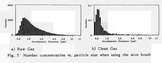
The tests with flame scarfing jet torches and wire brush for subsequent clea-ning of the flame-scarfed surface confirmed the results obtained during the previous research projects. The amount of dust released is so high that during the flame scarfing and especially during the subsequent cleaning of the flame-scarfed surface, extensive requirements of filtration and of protection for the operating personnel have to be met.
1.2 Particle Size Analyses
The particle size analyses, which were carried out with an Aerodynamic Par-ticle Sizer APS 33, revealed very similar results for the chisel hammer and
-spike hammer tests, as was to be expected, cf. Figs. 1 and 2. In both cases,
the curve of the particle number concentration is relatively flat. The main
fraction of the particles lies within the aerodynamic diameter range of 0.6 to
3 pm.
According to expectations, the grinding method produces a shifting of the
par-ticle size distribution towards smaller diameters (Fig. 3). The main fraction
of the particles lies between 0.7 and 1.5 pm.
Flame scarfing produces a clearly defined maximum between 0.8 and 1 pm
(Fig. 4), whereas brushing yields a similar particle size distribution as with
grinding (due to the high rotational speed), as was to be expected, cf. Figs.
3 and 5.
The accumulated particle mass distributions, however, show in all cases that
these particles play a subordinate role regarding their mass. The relatively
few particles with an aerodynamic diameter of over 4 pm account for a
to-tal mass proportion of over 90%.
2. Filtering Tests (B.5. and B.4.)
After completion of the preliminary tests, regenerative filters were
incorpo-rated into the suction conduit. During the tests, the dust loads were
deter-mined both upstream and downstream of the filtering plant, and particle size
analyses were carried out.
2.1 Filtering Plant
The dedusting system includes two filter elements of the suspended matter
classification "S" arranged behind each other and having a cartridge form. The
second filter element serves as a safety filter so that in case the main filter
is damaged, no contaminated air will enter the ambient air.
As soon as a given amount of dust has been deposited on the main filter,
which causes a pressure drop that can be selected freely beforehand, the
cleaning system is cut in automatically. In order to clean the filter, purified
compressed air is used which should also be free of water and oil. The
se-parated dust drops through a dust funnel with butterfly valve into a dust
collecting tank.
2.2 Results of Measurements
With all concrete stripping methods tried, the degrees of separation acchieved
with the filtering plant were appreciably higher than 99%. As was to be
ex-pected, the particle size distribution maxima in the clean gas are shifted
to-wards smaller particle diameters, cf. Figs. 1 to 5.
The pressure drop across the filter rises in relation to the amount of dust
re-ceived. In an unloaded condition, the pressure drop across the filter is 510 Pa
at a volume flow of 3000 m
3/h. The filter manufacturer recommends to start
cleaning at a pressure drop equal to 980 Pa. This limit value was set at the
switchboard of the plant. When this value was reached, the cleaning phase was
startet automatically. After the filter had been cleaned, the pressure drop was
in the order of 680 Pa. The filter was loaded 10 times and cleaned
automati-cally at a constant degree of separation.
With the particle size distributions occurring when stripping concrete, and at
raw gas dust contents of approx. 50 mg/m
3, the manufacturer guarantees that
the regenerative filter will have a service life of 2000 hours.
-Table I
Raw gas dust loads in the suction duct with different stripping methods
Stripping Method
Chisel Hammer Spike Hammer Grinding Device
Flame-Scarfing Wire Brush
Dust Loading in mg/m3
26,75 36,71 164,5
110,8 851,7
0.2 - r
0.6 1.0 2.0 4.0 6.0 10 15 Aerodynamic Diameter (urn)
0.6 1.0 2.0 4.0 6.0 10 15 Aerodynamic Diameter (urn)
a) Raw Gas b) Clean Gas
Fig. 1 Number concentration vs. particle size when using the chisel hammer
0.6 1.0 2.0 4.0 6.0 10 15
Aerodynamic Diameter (urn) 0·° 1.0 2.0 4.0 6.0 10 15 Aerodynamic Diameter (pm)
a) Raw Gas b) Clean Gas
Fig. 2 Number concentration vs. particle size when using the spike hammer
E
3
Ζ
0.6 1.0 2.0 4.0 6.0 10 15 Aerodynamic Diameter (μπι)
0.6 1.0 2.0 4.0 6.0 10 15 Aerodynamic Diameter (urn)
a) Raw Gas b) Clean Gas
Fig. 3 Number concentration vs. particle size when using the grinding device
200
1 0 0
-0.6 1.0 2.0 4.0 6.0 10 15 Aerodynamic Diameter (pm)
0.6 1.0 2.0 4.0 6.0 Aerodynamic Diameter (pm)
10 15
a) Raw Gas b) Clean Gas
Fig. 4 Number concentration vs. particle size when flame-scarfing
4000
llllllllllim..,—,_
0.2
o.i
ε
3
Ζ
Hlii«M.i....i
0.6 1.0 2.0 4.0 6.0 10 15 Aerodynamic Diameter (pm)
0.6 1.0 2.0 4.0 6.0 10 15 Aerodynamic Diameter (pm)
a) Raw Gas b) Clean Gas
Fig. 5 Number concentration vs. particle size when using the wire brush
2.6. Economie Comparison of Decontamination and Direct Melting with a View to Recycling Scrap
Contractor: Gesellschaft für Nuklear-Service mbH, Essen, Germany Contract N°: FI1D-0029
Working Period: January 1985 - June 1986 Project Leader: K. G. Janberg
A. Objectives and Scope
The decommissioning of nuclear facilities either requires the final disposal of large quantities of contaminated scrap metal or the deconta-mination to a degree which allows its further use in nuclear or other areas.
Decontamination technology is well developed and in most cases based on the application of highly corrosive agents or electrochemical proces-ses. Recently, direct melting has been added to these procedures as it allows for the separation of Cs and Sr from the base material. However, the volatile contamination agents have to be retained by appropriate filter systems.
The objective of this work is to carry out an economic study of decontamination, direct melting and super-compaction, with a view to recycling of scrap, in order to establish a state-of-the-art cost struc-ture for the decommissioning of nuclear installations. This economic comparison is based on actual clean-up or decommissioning work executed by the contractor under industrial conditions.
This study takes into account the nuclear installations in Germany.
B. Work Programme B.l. Review studies
B.l.l. Inventory of contaminated metal scrap until 1994. B.1.2. Review of existing decontamination methods.
B.1.3. Review of licensing conditions for recycling of decontaminated metal scrap.
B.2. Assessment of the investment and running cost of the three follow-ing procedures:
- decontamination of scrap metal followed by melting and release, - direct melting of scrap metal, followed by release,
- super-compaction followed by disposal as radioactive waste.
-C. Progress of Work and Obtained Results Summary
During this period, the inventory of contaminated scrap, the review of existing decontamination methods and licensing conditions were completed and the cost of procedures indicated in B.2. was assessed.
1. Compilation and review of basic information (B.l.)
- The normal scrap metal arisings lie between 20 and 40 tons per reactor and year. In the Germany this mass is complemented by the ones result-ing from backfittresult-ing (BWR power stations) and decommissionresult-ing (KRB A, Otto Hahn, KWL, KKN, VAK, FR2, MERLIN etc.) and eventually in the Nineties also WAK.
So, the total annual scrap mass from normal operation until 1994 will lie between 4,000 and 8,000 t complemented by approximately 10-15,000 from decommissioning. It would be higher if safe long-term enclosure would not be the reference concept for most reactor buildings.
- For the chemical decontamination, there is no upper limit for its application, while electropolishing is more suitable for the lower range, say < 100 - 200 Bq/cm2 for the time being. Direct melting is
licensed so far only for scrap having less than 74 Bq/g.
- In the FRG, recycling in the industrial area is limited to an activity level of 3.7 Bq/g and/or 0.37 Bq/cm2 as far as radiation is concerned.
If this application-limitation is not feasible, then the activity levels have to be lowered by a factor of ten, making control measure-ment rather difficult. This is the reason why recycling in form of
throw-away waste casks becomes more and more interesting with the increase in the mass of scrap metal.
2. Assessment of the investment and running costs of the three following procedures (B.2.):
- Decontamination by chemical procedures,
here, the cost range varies, of course, depending on the original contamination, geometry and total quantity in a range of 2.50 to 9 DM/kg.
- Direct melting,
as it is applicable only under 74 Bq/kg, it cannot be compared over the whole range of contamination, but it can be said that its cost-range lies between 3 and 9 DM/kg including cutting, transport and measurement. So, there is no clear and definitive cost advantage compared to decontamination under the existing licensing conditions. Super-compaction and direct disposal,
this is the only solution for extremely mixed scrap wastes of compli-cated geometry and unknown material composition. The cost ranges between 2.5 and 5.5 DM/kg. This procedure is to be ruled out for large
components of homogeneous constitution.
-3. PROJECT N°3:
DISMANTLING TECHNIQUES
A. Objective
The objective of this project is the development of the special techni-ques needed for dismantling the large steel components (e.g. reactor pressure vessel) and reinforced-concrete structures (e.g. reactor shield-ing) of redundant nuclear installations, account being taken of the particular requirements due to radioactivity.
B. Research performed under the 1979-83 programme
The following techniques have been tested and developed:
- thermal techniques such as plasma-arc and oxygen cutting and cutting by laser beam;
- mechanical techniques such as sawing;
- explosive techniques for the dismantling of concrete structures.
C. 1984-88 programme
The dismantling techniques needing further development should be chosen account being taken of the results of the first programme. Particular emphasis will be laid on the minimisation of secondary waste and contami-nation, and of occupational radiation exposure.
The necessary equipment for the remote operation of dismantling and other decommissioning techniques will be an important new aspect for investiga-tion under the proposed programme.
D. Programme implementation
At the end of 1985, seven research contracts were at the stage of execu-tion, and eight contracts were at the stage of negotiation.
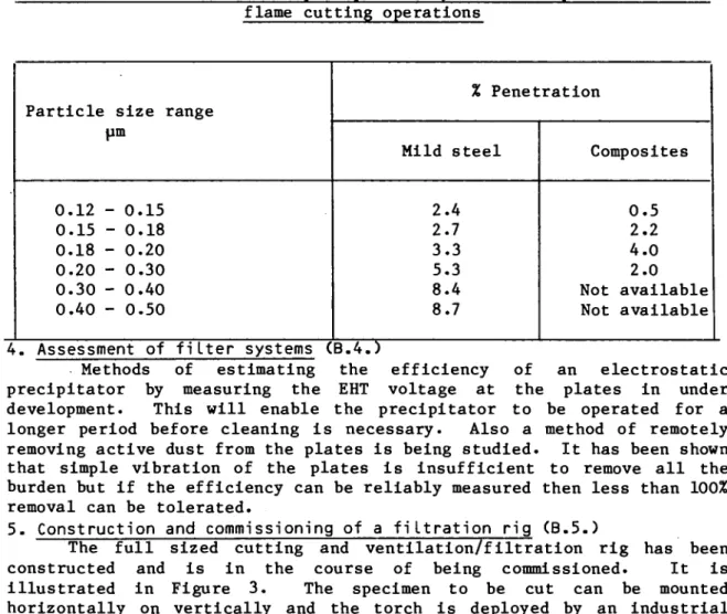
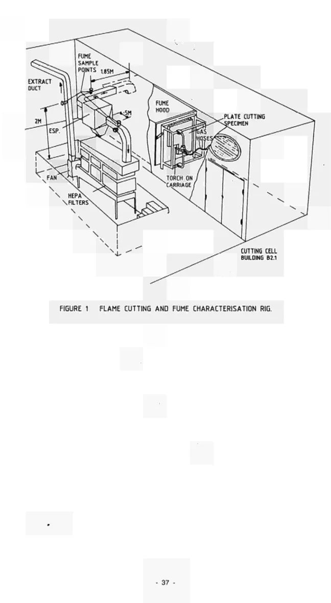
3.1. Ventilation and Filtration Techniques for Thermal Cutting Operations
Contractor: United Kingdom Atomic Energy Authority, Windscale Nuclear Laboratories, United Kingdom
Contract N°: FI1D-0006
Working Period: October 1984 - September 1986 Project Leader: J.R. Wakefield
A. Objectives and Scope
The dismantling of nuclear plant calls for the segregation of diffe-rent materials and combinations of materials. These are largely mild steels, carbon steels and stainless steels. A thermal segregation process has advantages in that it is less sensitive to material thickness and type and is more easily controlled by remote means. Its disadvantage is that it generates high concentrations of sub-micron aerosols which cause rapid plugging of absolute filters. To extend the life of these filters and to reduce the volume of secondary waste, some form of pre-filtration is necessary.
The object of this work programme is to: categorize aerosols produ-ced by a range of thermal cutting processes; identify suitable pre-fti-tration devices; test them against cutting aerosol challenge; recommend a suitable filtration system which minimises secondary waste production and the man-Rem dose to operators. This work will initially be carried out in a purpose-made rig and will continue to a full scale mock-up of the Windscale AGR plant.
Co-operation with CEA Saclay (contract N° FI1D-0007) will take place over the work period and will take the form of information exchange and the interchange of apparatus and personnel.
B. Work Programme
B.1. Literature survey for identification of former work and of alter-native techniques.
B.2. General investigation into aerosol behaviour for various cutting techniques.
B.3. Construction of a filtering rig and detailed study of various filtration systems.
B.4. Assessment of various tested filter systems for their appropriate-ness in decommissioning applications with active aerosols.
B.5. Execution of full size ventilation trials including aerosol deposi-tion in ductings and plate out on the decommissioning machine.
C. Progress of work and obtained results
Summary
The literature survey revealed considerable documentation on aerosol production from plasma torches and arc saws, largely under water, but none at all from oxygen powder cutting. It was therefore necessary to embark on a series of ranging runs using this method in order to determine the design of the experiments. These early indications were encouraging in that it was apparent that visibility of the workpiece was not to be a problem (only 1% of kerf is airborne) and that the main occupation lay with plate-out and filtration of activated steel aerosols. This arose from the discovery that a large proportion of the aerosols produced were submicron in size (40% of total) and so would be expected to lead to rapid blocking of the standard HEPA type filters.
A number of parameters of the cutting process were selected as being likely to influence the production rate of submicron aerosols. These included powder injection flow, cutting speed, cutting oxygen flow, size of cutting flame, and type of materials being cut. The latter also included composites typical of those present in the Windscale AGR plant. The results obtained show that powder flow rate and cutting speed have the most influence and that it is possible to determine values which produce the minimum aerosol production. Furthermore, this optimised production rate is one or two orders of magnitude greater than that obtained with zero powder flow. Hence there is a strong incentive to devise methods of oxygen cutting that do not require powder injection.
These experiments also demonstrated that the electrostatic
precipitator is a suitable prefiltration device but that additional development work on monitoring its efficiency and the safe removal of active dust is required.
All the above work was carried out in a small rig with a ventilation flow of 5000 rsß hr- 1. A considerably larger full scale reactor
simulant was constructed during the period of this review and is about to be commissioned. This will be capable of reproducing the intended ventilation flow in the Windscale AGR of 15,000 m3 h r- 1 and will
enable the earlier results to be corroberated.
Two meetings have been held in the UK with CEA Saclay and a work plan agreed. The prefiltration module developed at Saclay will be installed in the cutting/filtration rig and presented with the range of aerosols generated as in the experiments described in 2. and 3. below . Cross comparison with earlier results will be made from experiments carried out in both facilities.
Progress and results
1. Literature survey (B.1.)
The production of aerosols from cutting metal by the application of heat depends upon the torch characteristics and the material to be cut. Studies /l/,/2/,/3/ have been made in which these variables have been evaluated. Particle size distributions were found to be in the range 0.2 um to 0.3 pm for cutting stainless steel by plasma and oxyacetylene torch /2/. Aerosols production rates were also determined for a number of processes ranging from reciprocating saw to plasma torch /2/. Values in close agreement to these were also obtained for the oxypropane torch
131. It has been concluded that a standard HEPA type filter will block
-long before a radiation limit is reached for the types of activated steels encountered in nuclear plant /4/. Methods of improving the filter burden before blockage occurs have been suggested /5/ and followed by manufacturer /6/. In addition a form of prefiltration device will be necessary to prolong the life of the HEPA filters.
2. Investigations on aerosol behaviour (B.2.)
The work to date has concentrated on the oxypropane cutting systems with and without the addition of iron/aluminium powder. This was carried out in the rig depicted in Figure 1. The flame cutting torch and the vertical material frame are housed in a 120 m3 chamber with viewing
panels along one side. Clean air enters at one end and after passing over the cutting zone is collected in ducting via a hood. The ducting is equipped with portholes for the insertion of Anderson impactors and Millipore samplers and also 150 isokinetic sampling and traversing
take-offs. The prefiltration equipment (in this case an electrostatic precipitator), HEPA filters and the extract fan are mounted in series and exhaust to atmosphere.
The parameters investigated were derived from an initial list of eleven and comprise:
Powder injection flow. Cutting speed.
Cutting oxygen flow.
Flame size (via flame oxygen flow).
These were then related in turn to different steels viz:
Mild steel. Carbon steel. Stainless steel.
Composites of the above.
For each material and set of conditions the following principle parameters were measured within the duct.
Duct air velocity. Velocity profile.
Particle size distribution. Aerosol generation rate.
Filter differential pressure.
Chemical analysis of particles (for some runs).
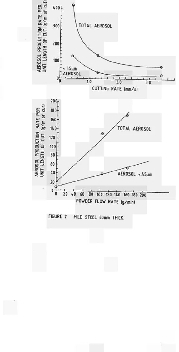
The results obtained for each run were plotted as aerosol generation, both total and submicron, against each of the selected parameters. An example of two such plots is given in Figure 2. These represent aerosol production per length of cut against cutting rate and powder flow rate. These were found to be the main parameters whch govern aerosol production. These results were for mild steel of 80 mm thickness.
Table 1 summarises the values obtained for this and other materials including simulants of those found in the Windscale AGR plant, for optimised cutting speeds and powder flows.
Table I
Aerosol production rate against cutting speed and powder flow for various materials
1
Material
Mild steel
Stainless steel
Hotbox (mild on stainless steel
Hoxbox (stainless on mild steel)
Pressure Vessel
Cutting speed mm. s-
-'-2.5
2.5
5.0
2.5
1.5
Powder flow rate g.min-!
100
100
80
140
140
Aerosol production rate
g . m- 1 of cut
20
60
23
40
30
This shows that the stainless steel sample produced considerably more aerosol than mild steel. The simulated hot box section produced results differing by a factor χ 2 depending from which side it was cut. The aerosol production rate fell by a further order of magnitude in the absence of powder injection so it is recommended that this method should be used only when essential. In the case of the Windscale AGR plant this would be when penetrations need to be made in thick mild steel plate, when the material geometry is variable, when it is difficult to maintain a regular stand off distance and when cutting composites of materials such as the hot box and the reactor pressure vessel.
3. Preliminary trials on an electrostatic precipitator (B.3.)
Some preliminary trials have been carried out on an electrostatic precipitator on a prefilter. A particle spectrometer was used to measure concentrations upstream and downstream of the precipitator. In runs when mild steel and composite materials were cut using both iron and iron/aluminium powders it was shown that an efficiency of better than 90% was obtained for removal of particles of less than 0.5 pm. Table II gives the detailed results.