INTERNATIONAL CONFERENCE ON ENGINEERING DESIGN, ICED’07
28 - 31 AUGUST 2007, CITE DES SCIENCES ET DE L'INDUSTRIE, PARIS, FRANCE
VIRTUE INTEGRATED PLATFORM: HOLISTIC
SUPPORT FOR DISTRIBUTED SHIP
HYDRODYNAMIC DESIGN
Zhichao Wu1, Alex H B Duffy1, Dracos Vassalos2, Phil York2, and Ian R Whitfield1
1 CAD Centre, University of Strathclyde, Glasgow, UK 2 Naval Architecture and Marine Engineering, University of Strathclyde, Glasgow, UK
ABSTRACT
Ship hydrodynamic design today is often still done in a sequential approach. Tools used for the different aspects of CFD (Computational Fluid Dynamics) simulation (e.g. wave resistance, cavitation, seakeeping, and manoeuvring), and even for the different levels of detail within a single aspect, are often poorly integrated. VIRTUE (the VIRtual Tank Utility in Europe) project has the objective to develop a platform that will enable various distributed CFD and design applications to be integrated so that they may operate in a unified and holistic manner. This paper presents an overview of the VIRTUE Integrated Platform (VIP), e.g. research background, objectives, current work, user requirements, system architecture, its implementation, evaluation, and current development and future work.
Keywords: Distributed design, integration, hydrodynamics, ship design
1 INTRODUCTION
Ship hydrodynamic design today is often still done in a sequential approach [1]. In its basic form, current work practice for CFD analysis starts with a ship surface description extracted from a CAD system. A computational grid is generated based on this surface and saved for resistance calculations. Several variants are defined by hand for minimising the wave making resistance, each based upon the results of the previous variants. The best variant is then selected as a starting point for a viscous flow optimisation of the aft body. The optimisation is based on the knowledge of the naval architect, who will keep in touch with his colleagues for advice. Subsequent studies include the propeller, hull-pressure fluctuations, cavitation and performance in calm water. The wake field of the hull is static input to this optimisation. Additional sea-keeping calculations may lead to a further adjustment of the hull or appendages. Finally, manoeuvring characteristics are determined and if deemed sufficient, the design analysis is finished. Results are presented to the customer on paper or through off-line animations.
The drawbacks of this approach are evident. Issues requiring improvement are [1]:
1. As the tools used for the different aspects, and even for the different levels of detail within a single aspect, are often poorly integrated, the consistent use of hydrodynamic prediction tools in design is not always efficient and therefore often not fully adopted;
2. Sequentially dealing with separate hydrodynamic design aspects precludes fully taking into account the mutual influences and interactions between those aspects;
3. The interaction with the customer (e.g. a shipyard representative) is important to define the available optimisation space and constraints. This interaction needs to fit into the short
timeframe typically available in ship design. Today‟s practice usually prevents such interaction.
To address the first drawback, it is desired to significantly improve the level of integration while maintaining an open and flexible environment. Consistently sharing and distributing information at all levels needs to be supported to a much higher degree so as to increase productivity and to consider the various hydrodynamic design aspects holistically rather than sequentially.
optimisation regularly addresses the minimization of wave resistance which can be calculated with reasonable accuracy and acceptably fast today. Use of RANSE solvers in formal optimisation is still limited to a few academic studies.
With respect to the third drawback, an essential part of CFD results is the general insight in the flow characteristics for a particular design. The only effective way to convey that insight is through visualisation. A crucial element in the desired collaborative working between hydrodynamic institutes / consultants and the designers from shipyards therefore is the possibility of a joint inspection of the results by state-of-the-art visualisation.
The objective of VIRTUE (the VIRtual Tank Utility in Europe) project aims to develop a platform that will enable various distributed CFD and design applications to be integrated so that they may operate in a unified and holistic manner [1]. The specific objectives are to [1]:
Detail the requirements specification for the platform in order to ensure all aspects, features and modes of operation are fully defined.
Develop and define data management techniques to facilitate data transfer between currently disparate sets of tools.
Develop and implement the integrated platform to manage data transfer and the platform‟s performance, process management and user interaction.
Define, develop and implement an appropriate user interface that shall support multiple user requirements through distributed collaborative working.
Provide an optimisation tool set to support specific hydrodynamic local optimisations integrated within a global optimised design.
Address and exemplify multi-objective, multi-criteria optimisation for a number of typical hydrodynamic problems encountered in ship design and marine engineering.
Support the evolution of the platform and integrated tools, and provide a parameterised design model, through the development, implementation and utilisation of data mining and machine learning techniques.
Develop and implement a holistic visualisation interface through integrated post processing of simulated data.
This paper aims to present the design of the Virtue Integrated Platform (VIP), its implementation (i.e. a prototype system of VIP), and its evaluation. The rest of the paper is organised as follows. Section 2 presents current works, which serve as basis for this research. User requirements for the platform are specified in section 3, which are elicited through a questionnaire. The architecture of the platform is then designed to address such user needs, presented in section 4. Section 5 describes the implementation of the VIP with some screenshots of VIP prototype system. The prototype system is evaluated by potential users and feedback from users is analysed, shown in section 6. Finally, section 7 presents a conclusion.
2 CURRENT WORKS
The VIRTUE project is based a number of past projects (including VRShips-ROPAX, Fantastic, NEUTRABAS, and Mobiship), and current technologies (e.g. visualisation technology, collaborated design technology). VRShips-ROPAX (VRS) is a pan European maritime project funded under the
„competitive and sustainable growth‟ of the 5th Framework in European Research. A strategic objective of VRS is to integrate information technology into the life cycle of a product. The project focuses upon integrating current effort dispersed throughout Europe to provide a standardised platform upon which a variety of maritime industries can function. The project is based on a partnership of 33 different organisations from academic institutes, marine consultancies, marine research organisations, naval architects, ship builders and operators, port authorities and standards organisations. The two main deliverables from the project will be a „generic virtual platform‟ and „ship platform of critical
technologies‟. The virtual platform focuses on ship data to support product life cycle evolution rather
management, support collaborative working, develop multi-disciplinary optimisation across previously disparate tools, integrate visualisation of complex data, data mine CFD parametric data for knowledge extraction and tool evolution, validate and evolve the integrated tools through linking design, test and extracted knowledge models.
The Fantastic project, carried out during 2000-2003, focused on the optimal design of ship hull shapes. It was led by Fincantieri, technically managed by Sirehna, and involved European shipyards (Fincantieri, IZAR, FSG), as well as major research centres in the shipbuilding domain (MARIN, HSVA, SSPA) together with specialists of CAD and parametric modelling (NAPA, TU Berlin), software providers and developers. The project aimed at investigating and developing parametric and optimisation approaches within the design of ship hull shapes, taking into account mainly hydrodynamic aspects. It has led to approaches that are now being used in some current design work by the participants. Major achievements were the development of various parametric modelling approaches and tools for shape management, and the involvement of advanced technologies for design space exploration and optimisation, namely through the modeFrontier environment. The project has brought the necessary experience with these tools that now makes it possible to foresee a further integration level and an extension of their exploitation towards global design involving more hydrodynamic and other aspects.
The objective of the NEUTRABAS project was to develop standardised methods for the storage and exchange of data defining shipbuilding and ocean engineering products as representative examples of large multifunctional systems. Building on the work of ESPRIT project 322 (CAD*I) and CAD interface formats such as STEP and PDES, the project defined the principles of application-oriented reference models relating to complex maritime products, which include many services and machinery systems within a constraining steelwork envelope. A Neutral Product Definition Format was defined to serve as an exchange and archiving medium for the complete standardised product definition model. The project provided international standardisation in the area of product data exchange technologies (STEP) with a valuable contribution.
Mobiship (G3RD-CT1999-00026) “Model based initial and basic ship design” was a project dedicated to establish the specifications of a common data model to be used in CAD and analysis tools from early up to detail ship designs. Some parts of this data model are common with VIRTUE requirements and may be shared to ensure compatibility with CAD systems involved in Mobiship (NAPA, TRIBON and FORAN).
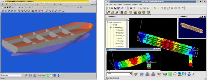
[image:3.595.125.472.550.685.2]Visualisation is an important requirement for any kind of CFD analysis. VIRTUE will benefit from the use of existing powerful packages dedicated to scientific visualisation, integration and data exchange. One leading technology is brought to the project by the Principia group that includes the OpenCasCade company. OpenCasCade provides development teams with powerful software components and companies with customised software tools. The latest platform available, SALOME, allows building powerful coupled scientific applications including automation of analysis studies, coupled (multi-physics) problems, and optimisation, see Figure 1.
Figure 1 Example of the SALOME application
Language), XML (eXtensible Markup Language), and RMI (Remote Method Invocation), enable designers distributed in different locations to access catalogue, and design, information on components and sub-assemblies, design tools, and services, and to communicate with other members in a design project. Agent technology has been applied to support collaborative design. Parunak (1998) argued
“agents are best suited for applications that are modular, decentralised, changeable, ill-structured, and
complex” [7]. Agent theory is being integrated with other technologies, such as web, and Computer Supported Collaborative Work (CSCW) to support collaborative design. Such technologies are used as basis for development of supports for distributed computational environment within VIRTUE project.
3 USER REQUIREMENTS
The Virtue Integration Platform (VIP) is required to provide management and support for all of the CFD and design tools required within an integrated CFD ship design environment. To do this it is first necessary to identify the user requirements. Such requirements should reflect the different scenarios for which the platform would be used, with the main users being the basins in the project partnership. The first task was to identify the key tools needed to address an overall, holistic, ship CFD analysis. Additional tools could then be integrated into the platform at a later date. A comprehensive coverage of appropriate requirements of the user was considered including user interface, visualizations and
scenarios, and addressed “why” and potential benefits. The requirements were elicited through a questionnaire:
Communication technology: The VIP must be able to provide a reliable and secure access for internal and external users, depending on different identified user roles. A second server/mirror site should be considered to circumvent communication downtime and a single point of failure should not block the entire system and lead the users to bypass the platform. The platform should provide a notification of errors and should continue operation at the point of error after problems have been solved e.g. include results from parallel executions outside the platform (e.g. long run RANSE computations).
Process control: Predefined processes, where a process is defined as a sequence of one or more tasks, should be available. Users should be able to construct, modify and run particular
processes depending on different user roles. The platform must also provide a mechanism to record and visualize the version and the state of processes. It should be possible to back-step in the process chain and repeat consecutive steps with modified parameters, particularly for cases of errors or abnormal end of process, and it must be possible to perform repetitive tasks.
Project management: The platform should provide a means to monitor the work progress and the project manager must be able to obtain an overview at any time, and be able to inform customers on work progress upon request. The project manager needs also to be able to specify the different levels of user access to the project data. They should have an option to specify permanence and to determine the data to be provided before closing a project.
Optimization: It was clear that most of the basins and design consultancies currently do not employ optimization techniques as standard practice, over 60% responding rarely or never. Thus, optimization methods were not considered a primary concern for the initial phase of the VIP. However, the project partners envisage an increasing requirement for optimization so that by the end of 2009 optimization methods will be fairly common practice. Further, some partners indicated that by 2009 optimization methods based on RANSE computations are “desirable”. This implies that current methods address only computations based on potential theory. The feasibility of this has yet to be determined. However, the VIP would require an optimization tool that can store optimization history, capture generated data and re-use data from previous computations.
Data Mining and Navigation: Requirements for this aspect of the platform needs further investigation but the notion is that it will provide direct comparisons to be made between data generated experimentally and that generated through simulations to facilitate the verification and validation of the underlying computational models.
facility for model test and full-scale trials data. It must also be possible to compare and visualize experimental and computational results.
Visualization: The project partners generally use third party software for visualization of the results and post-processing. A wide variety of different types of data, ranging from simple 2D to large 3D time dependent field data is used. The most complex and frequently used presentation being the visualization of 3D field data. The data may be time dependent and the grids may be fixed or moving. Computed data needs to be compared with experimental (non complete) data or variants of the computation and any differences should be quickly visible. The visualization should also provide a means for probing and extracting 1D and 2D data from a 3D data set and different audiences will influence the type of illustration, for example, a scientific or a more
“commercial” (e.g. ray tracing) illustration. To explain computation results to non CFD-experts it must be possible to include “mock ups” of the 3D geometry into the visualization scene. A collaborative visualization for experts sitting at different computers is also desirable.
Data Management: A storage medium (e.g. common model) should support the communication of the integrated tools. A version control system should be implemented to allow the tagging of data states and the platform should supply an estimation of storage (and CPU) requirements and issue a warning if unreasonable resources are required. The platform should take care of
minimizing the data transfer and should provide mechanisms for data import and export, especially for legacy data.
User Interface: A number of the interface requirements are alluded to in the above. However, the interface should assist the user with the navigation and progress of a project. It should allow zooming in and out of a process. Different views should be provided depending on user roles so that viewing, reading and writing authorization should be handled according to those roles. The VIP should show data dependencies and allow the existence of invalidated data to be clearly marked. Inconsistent data should be clearly identified and the reason provided to the user. Further, the user must be able to start (and stop) the (CFD) tools interactively.
4 SYSTEM ARCHITECTURE
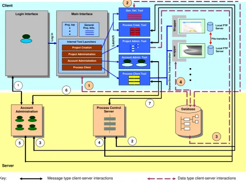
To meet the nature of distributed computation, the VIP has a server-client type architecture. The VIP serer software can be hosted in a server machine, while VIP clients can connect with server software remotely through Internet and make different types of requests. The server can response to client requests with predefined actions. The architecture of the VIP is depicted in Figure 2 that describes the client and server components and their interactions.
The server components consist of account administration server, process control server and a database server. The account administration server stores and manages user accounts and is connected with the login interface to validate user logins. Process control server controls the execution of project process. A VIP project includes one or more project processes, while a process has one or more task that runs a predefined logical sequence. The process server ensures that the right task is undertaken by the right users at the right time. A native XML database (called DBXML) is employed as a medium for data storage. The reason for the choice of a XML database is that XML (eXtensible Markup Language) is neutral data format and a XML database can accommodate the needs for different data format from different design and simulation tools. The VIP uses a novel data management approach, called minimal data approach. Within such an approach, the physical data are store in local machines while the pointers of the data are stored in a central database. The data management approach is elaborated in [8].
uploading, downloading, deletion, adding, and updating, etc) and data conversion, and the launch those tools through the platform (i.e. through running the executables). Local FTP servers are running in local machines and enable physical files transfer between local machines.
Two types of interactions can be categorised, namely message type (depicting with black colour arrows and number from 1 to 7 in Figure 2) and data type (depicting with brown colour arrows and number from 1 to 4 in Figure 2). The message type communication mechanism is described in Figure 3, which enable remote evocation of methods between two computing components A and B (e.g. a client and a server). Communication protocols are defined using XML and is communicated through sockets. Figure 4 shows an example communication protocol. It has a root element called
“VIPMethod”, which has four child elements, namely “Sender”, “Receiver”, “MethodName” and
“Inputs”. Such child elements define the sender, receiver, the method to evoke, and inputs for such a method (e.g. user account name and user password shown in Figure 4). Parsers (e.g. parser A and parser B) are designed for each component, aiming to parse the communication protocols and extract information from it. The parser then triggers methods in a component and to perform different actions. Different communications/interactions between client and server are defined and elaborated as follows:
Interaction 1: The login interface interacts with the account administration server to validate user logins.
Interaction 2: Process creation tool can upload created processes to process control server. From the process creation tool, users can make requests to the server to the project processes that are running in the server.
Interaction 3: From project creation tool, users can load registered users from administration server and allocate/register them to projects. The registered information will be recoded within the account administration server.
Interaction 4: The project administration tool interacts with process control server when project is created, deleted or modified in that project processes are added or modified or deleted from the server.
Interaction 5: When a project is deleted, users‟ registration information to the project (recorded in the account administration server) should be removed
Interaction 6: Account administration tool interact with account administration server to update account registration information.
Interaction 7: Process client tools can visualise project processes that are running in the process server. When the states of process/tasks are changed in process client, they are updated in the process control server. The process control server also co-ordinate the sequence of tasks that are executed through process client.
The data-type interactions are associated with the DBXML database server and the manipulation of physical data or data pointers. The VIP client can connect with the database server and manipulate data items that are stored within the database. The interactions are elaborated as follows:
Interaction 1: The general project information that is stored in the database is retrieved by the main interface and is displayed to users.
Interaction 2: General project definition tool can support the definition of general project information, and upload such information to database or download it from the database.
Interaction 3: For each VIP project, a collection is created in the database and all project data is stored in the connection. When a project is deleted from the platform, the project administration tool is connected to the database and remove the collection from the database.
Figure 2 VIP architecture Component A Component B Parser A Parser B Protocol Communication
Trigger Trigger
[image:7.595.170.421.528.718.2]Methods Methods
Figure 3 Communication mechanisms
Server Client
Account Administration
Process Control
Server Database
Login Interface Main Interface
Proj. list General Proj. Info.
Internal Tool Launchers
Project Creation
Project Administration
Account Administration
Process Client
Gen. Def. Tool
Process Creat. Tool
Process Client Tool
w ra ppe r Wra ppe r D es ign /S im u l. To o ls inte gr at ion Local FTP Server Local FTP Server Log in
Account Admin. Tool Project Admin. Tool
L aun ch
Key: Message type client-server interactions Data type client-server interactions 1
7
2 6
4
5 3
4 2
3 1
<?xml version="1.0" encoding="UTF-8"?>
<VIPMethod>
<Sender>VIPUserInterface</Sender>
<Receiver>AdministrationModule</Receiver>
<MethodName>RequestUserAccount</MethodName> <Inputs>
<UserAccountName>String</UserAccountName> <UserPassword>String</UserPassword>
</Inputs> </VIPMethod>
Figure 4 An example communication protocol
5 IMPLEMENTATION
A prototype system, called VIP0.2, has been implemented using Java programming language. The VIP
server runs and is hosted in a server machine. Users won‟t be able to see the server software and they
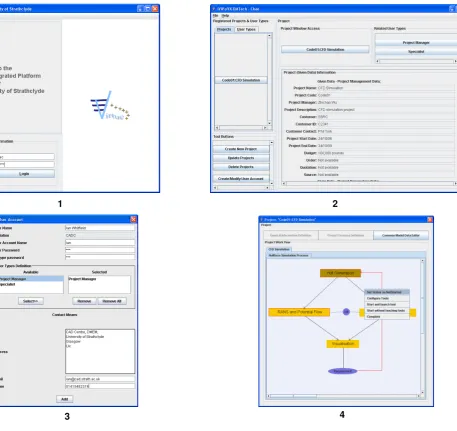
use VIP clients to interact with the platform. Some screenshots of the VIP clients and generic wrapper are shown in Figure 5 and Figure 6. Screenshot 1 in Figure 5 depicts the login interface of the VIP0.2. Users can type in their user name and password to log into the platform. Screenshot 2 in Figure 5 shows that main interface of VIP client, where users can see a list of registered project, a number of buttons to launch different tools (e.g. project creation tool, etc), and general project information.
Within the “Project Window Access” panel, there is button that can launch the process client tool.
Screenshot 2 in Figure 5 shows a dialogue that users can define a new user account. The elements for a user account are modelled as user name, user affiliation, user account name, user password, user type,
3 4
[image:9.595.106.564.53.484.2]1 2
1
3
[image:11.595.129.459.52.534.2]4
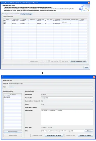
Figure 6 Screenshots of a generic wrapper
6 EVALUATION
VIP0.2 was distributed to VIRTUE project partners for evaluation. An evaluation form was designed, which include questions on different aspects of the VIP0.2, including user login and validation, user type support, general project information definition, process creation, expertise allocation, design and simulation tool allocation, project administration, configuration mode of the tool wrapper, enactment mode of the generic wrapper, task co-ordination support, data creation, storage and version management, data storage and retrieval, and data consistency support. An example question is like this
1 2 3 4 5
Very Badly Very Well
6
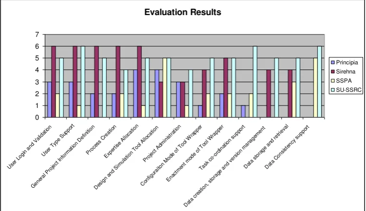
Four evaluation forms were filled in by four project partners, namely Principia, Sirehna, SSPA, and SU-SSRC. The feedback from partners are compiled and analysed, and the evaluation results are shown in Figure 7. Figure 7 illustrates that partners have quite mixed attitudes towards VIP0.2. Principia gave positive rates for “expertise allocation” and “design and simulation tool”. That is, the VIP0.2 supports allocations of available expertises to a project and allocation of available design and
simulation tools to tasks quite well. However, the feedback for “general project information
definition”, “project creation”, “configuration mode of tool wrapper”, “enactment mode of tool wrapper” and “task co-ordination” are negative (i.e. the rates are below “3”). The overall feedback from Sirehna is quite positive. Apart from the aspects of “design and simulation tool allocation” and
“project administration”, all the rates for other aspects of the platform supports are given a rate of “4” or higher. Very different from Sirehna, SSPA had a negative feedback to the prototype system. Except
that they rated both “Data Consistency Support” and “design and simulation tool allocation” “5”, other aspects of the platform are rated “3” or lower. SU-SSRC had very positive feedback to the system. All rates to different aspects to the system are given a value of “4” or higher. The overall feeling from all feedback is that VIP0.2 provides the required functionalities, however improvements need to be made so that the system can be more easily used.
Evaluation Results 0 1 2 3 4 5 6 7 Use r Log
in a nd Va
lidat ion
Use r Typ
e Su pport Gen era l Pro ject Info rma tion Def
inition
Pro cess Cre atio n Expe rtise Allo catio n Desi gn a
nd Si mula tion Tool Allo catio n Pro ject Ad
mini stra tion Con figura iton Mo
de o f Too
l W rapp er Enact ment mo de o
f Too l Wra
pper
Task co-o
rdin atio
n su pport
Dat a cre
atio n, st
orage and
versi on ma
nage ment
Dat a st
orage and retri eva l Dat a Co
[image:12.595.110.486.369.586.2]nsist ency supp ort Principia Sirehna SSPA SU-SSRC
Figure 7 Evaluation results
7 CONCLUSION
The user requirements for the platform is revisited, based upon the experience to use VIP0.2. The platform is then re-designed and addresses new user needs, and VIP0.2 evolves. It should be noted that VIP0.2 aims to implement the key user requirements, such as requirements for communication technology, process control, project management, visualisation, data management, and user interface. Other requirements, including optimization, data mining and navigation, and validation and validation, will be addressed in the future releases of VIP.
ACKNOWLEDGEMENT
This research is funded by the European Commission (grant No. TIP5-CT-2005-516201), which is part of EU 6th Framework Programme in Sustainable Development, Global Change and Ecosystems.
REFERENCES
[1] VIRTUE: The VIRtual Tank Utility in Europe, EU 6th Framework Program in Sustainable Development, Global Changge and Ecosytems, TIP5-CT-2005-516201, Jan 2005 to December 2009, http://www.virtual-basin.org/.
[2] Cutkosky, M., et al., PACT: An Experiment in Integrating Concurrent Engineering Systems. IEEE Computer, 1993. 26(1): p. 28-37.
[3] Toye, G., et al. SHARE: A Methodology and Environment For Collaborative Product
Development. in Proceeding of Second Workshop on Enabling Technologies: Infrastrcuture for Collborative Enterprise. 1993: IEEE Computer Society Press.
[4] Shen, W., et al., An Experimental Environment for Exchanging Engineering Knowledge by Cognitive Agents, in Knowledge Intensive CAD-2, M. Mantyla, et al., Editor. 1996, Chapman & Hall: London. p. 19-38.
[5] Huang, G., et al., Web-based Product and Process Data Modeling in Concurrent 'Design for X'. Robotics and Computer-Integrated Manufacturing, 1999. 15(1): p. 53-63.
[6] Rodgers, P., et al., Design Support Using Distributed Web-based AI Tools. Research in Engineering Design, 1999. 1999(11): p. 31-44.
[7] Parunak, H. What Can Agents Do in Industry, and Why? An Overview of Industrially-Oriented R&D at CEC, Cooperative Information Agents II: Learning, Mobility and Electronic Commerce for Information Discovery on the Internet. in Second International Workshop, CIA'98. 1998. Paris, France: Springer.
[8] Wu, Z., Duffy, A, Vassalos, D, York, P, Liu, S, and Whitfield, I. A Minimalist Data
Management Approach for Integrated Design Systems. in ICED. 2007. CITE DES SCIENCES ET DE L'INDUSTRIE, PARIS, FRANCE, to appear.
Contact: Z Wu
University of Strathclyde
CAD Centre, Department of Design, Manufacturing, and Engineering Management 75 Montrose Street
Glasgow G1 1XJ UK