Abstract: Now a days the most popular method used for telecommunication signaling is DTMF. Using DTMF in applications isn't new, however the reason for this paper is to deliver another way to deal with this. The main goal of this project is to design a DTMF controlled robot using a mobile phone over farther distances. This paper is mainly focused on building the robot which will navigate through the obstacles using the Skype video calling app and will help people to communicate with disabled/oldage persons at their homes without any helping hand, surveillance of homes or companies when they are away, and in defence sector. This robot doesn’t need anyone’s assistance to even lift the call as we can put the Skype on auto-answering mode and we can control the robot from wherever we want. Future works involve a hybrid supply system of both solar and conventional battery, wireless charging, and modifying it into a quadcopter. We are also using servo motors to give the robotic hands and neck movement. Keywords: DTMF Decoder, Aurdino UNO, Motor driver, Servo motor, Skype, Proteus software, MIT app inventor, Wireless charging.
I. INTRODUCTION
We the humans will invent the new technologies every now and then which will improve your lifestyle and provides us comfort and safety. But the sustainability of that technology depends upon the various applications it serves. DTMF is one such technology which is invented to communicate in telecommunication sector, but it doesn‟t sustain longer periods in telecommunications. We invented even more advanced technologies like SIP. But DTMF is still used and explored area because of its versatility in its applications. The use of DTMF in combination with electronics and solar can do some crazy things, one of such applications we are going to implement.In earlier days, our telephone systems were operated by manually in a telephone exchange room. The callers will pick up the phone and giving instruction to the operator to connect their destination line.
Revised Manuscript Received on June 12, 2019
Vishal Kumar Singh, Student EEE, Gokaraju Rangaraju Institute of Engineering and Technology (JNTU-H), Nizampet, Hyderabad, India.
Koduru Sriranga Suprabhath, Student EEE, Gokaraju Rangaraju Institute of Engineering and Technology (JNTU-H), Nizampet, Hyderabad, India.
Mounica Nutakki, Student EEE, Gokaraju Rangaraju Institute of Engineering and Technology (JNTU-H), Nizampet, Hyderabad, India
Jami Sridevi, Student EEE, Gokaraju Rangaraju Institute of Engineering and Technology (JNTU-H), Nizampet, Hyderabad, India
Sri Vidya Devi Palakaluri, Student EEE, Gokaraju Rangaraju Institute of Engineering and Technology (JNTU-H), Nizampet, Hyderabad, India
.
The DTMF technology provides ultimate solutions for the telephone industries which is used to switch two lines automatically. The DTMF stands for „Dual Tone Multi-frequency‟ which is one of the techniques for converting the analogue signal to digital using DTMF decoder. The DTMF decoder circuit mostly used in mobile communications system which recognizes the sequence of DTMF tones from the standard keypad of the mobile phone. DTMF controlled Robot runs over mobile DTMF innovation that exists in Dial tone [1].
Fig1. Block diagram
Moreover the authors knowledge up to now had gone through a number of projects which did not carved our interest out to modify any of them with our innovative idea. Then came across this project named “DTMF controlled robot”, this project retrieves its originality from the “Bluetooth controlled Robot” but Bluetooth range of cell phones are too short to make them controllable over long ranges. DTMF controlled robot can be controlled over a wide range but you can‟t see the robot on a phone call. So, what motivated us is the question “Can‟t we control the robot kept in any part of The world from any other part of the world via Video call and with the help of DTMF ones simultaneously (Provided there is a working WI-FI connection in these 2 areas) The rest of the paper is organized with
analysis and design of robot with the circuit diagram
Vishal Kumar Singh, Koduru Sriranga Suprabhath, Mounica Nutakki, Jami Sridevi, Sri Vidya Devi
Palakaluri
along with the algorithm followed by the results.
II. LITERATURE SURVEY
We use radio frequency robot control methods which has limitations with respect to frequency, bandwidth, range of operation and operation control. This paper proposes a method or technology which increases the range of operation and operation control, here we use mobile communication technique. By utilizing the variety of tones present in the number pad of our mobile we can operate and control the smart bot this is application is known as DTMF (Dual Tone Multiple Frequency). In our design Mobile Controlled Robot utilizing DTMF, we execute a shrewd rationale and control framework dependent on installed frameworks utilizing a micro controller, here the smart bot is made to operate by mobile signal [4], in which we make a call to the cell phone which is placed over the smart bot working at auto answer mode. In simple words we can say that our mobile acts as remote control [6]. We use the SKYPE application for making video call, this video call technology acts like a feedback for the user on robot operations.We find various applications of DTMF in Military sector, Industrial security, controlling of household appliances. All these can be made more reliable and controllable using the mobile video calling.
III. MOTIVATION
Our knowledge up to now had gone through a number of projects which did not carved our interest out to modify any of them with our innovative idea. Then came across this project named “DTMF controlled robot”, this project retrieves its originality from the “Bluetooth controlled Robot” but Bluetooth range of cell phones are too short to make them controllable over long ranges. DTMF controlled robot can be controlled over a wide range but you can‟t see the robot on a phone call. So, what motivated us is the question “Can‟t we control the robot kept in any part of the world from any other part of the world via Video call and with the help of DTMF tones simultaneously (Provided there is a working WI-FI/mobile data connection in these 2 areas). Also the hybrid power supply system, wireless charging and future scope encouraged us to choose this as our research project.The rest of the paper is organized with circuit diagram of robot along with software/app used, algorithm followed by the results and future work.
IV.CIRCUIT DIAGRAM
We have used Proteus software to build and run our model in the form of a circuit diagram as shown in fig.2. Circuit diagram for Arduino based DTMF Controlled Robot resembles other robots like PC controlled, Line
Follower, Gesture Controlled Robot etc. Here one motor driver is connected to Arduino for driving robot [1].
Arduino UNO is the controller which acts the bridge between the DTMF decoder and the motor driver. The tones decoded will be given to the aurdino, particular input will be assigned to perform the particular operation through the aurdino programming. The motor driver circuit is used to amplify the amount of voltage and current in order to make the DC Motors operate, this can be achieved by H BRIDGE configuration.
Motor driver‟s input pin 2, 7, 10 and 15 is connected at Arduino digital pin number 8, 9, 10 and 11 respectively.
Fig2. Circuit Diagram
Here we have used four DC motors to driver robot in which two motors are connected at output pin of motor driver 3 and 6 and other two are connected at 11 and 14.A DTMF decoder attached with this circuit and this decoder is plugged into a mobile using an aux wire for receiving command or DTMF Tone. [8] DTMF decoder pins D0-D3
is directly connected with Arduino‟s pin number A2, A3, A4, A5. Servo motor is connected to the output pin 3. A 12 volt Battery / 12V solar panel is used to power the motor driver.A Buck regulator is also used to step down the voltage to 5 volts to power the Arduino, DTMF decoder, and servo motors.
V. WORKING
So as to control the robot, you need to make a Skype call to the mobile phone connected to the robot (through mobile phone) from any phone, which sends DTMF tones on pressing the numeric buttons [3]. The Skype containing
mobile phone attached to the robot is kept in „auto answer‟ mode. Then we have built an app in MIT app inventor phone in the robot. These tones are fed to the circuit by the headset of the mobile
and sends the equivalent binary number (8421 code) to the microcontroller/ Arduino. According to the program in the microcontroller, the robot begins moving.
Fig: 3MIT inventor app for DTFM control
When you press key „FRONT‟ button that is DTMF equivalent of numeric „2‟ (8421 equivalent 0010) on your mobile phone then the microcontroller output is that Port pins 9 and 11 are high. The high outputs of the microcontroller drives the motor driver (L293D) ports 2 and 10 high. Port pins 2 and 10 drive the four motors in forward direction. Similarly, move for left turn, rightturn, backward motion and autonomous mode. If you press „CAM UP‟ button that is DTMF equivalent of numeric „3‟ (8421 equivalent 0011) on your phone then the microcontroller output is high for port 3. Port 3 operates the servo motor and brings the camera up. Similarly, Servo operates for down and straight positions online as shown in fig.3, which accumulates all the DTMF tones in the form of commands for the robot.The DTMF tones are thus created from this app are received by the mobile.
VI. ALGORITHM
The algorithm of the project can be explained in the following steps:
Step 1: Initially power supply is given to the DTMF robot that is to Arduino, DTMF decoder, driver, and servo motors. Step 2: Video call is made from a remote mobile using Skype calling app.
Step 3: Call is received by the robot mobile automatically. Step 4: Directions are given by the operator using Skype video and MIT inventor app.
Step 5: When FRONT button is touched down in the app, robot moves forward, and stops when touched up.
Step 6: When BACK button is touched down in the app, robot moves backward, and stops when touched up
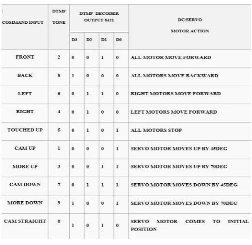
[image:3.595.303.556.55.301.2]Step 7: When LEFT button is touched down in the app, robot moves left, and stops when touched up.
Fig 4. Commands for robot control
Step 8: When RIGHT button is touched down in the app, robot moves right, and stops when touched up.
Step 9: When CAM UP is pressed in the app, robot camera raises 45 degrees up.
Step10: When MORE UP is pressed in the app, robot camera raises 70 degrees up.
Step 11: When CAM DOWN is pressed in the app, robot camera goes 45 degrees down.
Step 12: When MORE DOWN is pressed in the app, robot camera goes 70 degrees down.
Step 13: When CAM STRAIGHT is pressed in the app, robot camera comes to its initial straight position as shown in fig.4.
Step 14: Surveillance should be possible through camera present in advanced mobile phone associated with DTMF Controlled robot.
[image:3.595.111.221.110.261.2]Fig: 5 Research Project Model
VIII. CONCLUSION
In this paper a new Solar powered DTMF controlled robot using Skype has been designed fig.6 and implemented successfully, its application to control the robot from the farther distances has been tested. The applications of DTMF in various fields are discussed. The future developments of this project like wireless charging are in progress. We have used ten DTMF tones as of now in our project and are working on utilising all the tones which are left. We are using those tones to give our robot its hands so that it can be
Fig: 6 Battery replaced with solar panel
brought forward to do more tasks. The conventional battery has been replaced with the solar cells/panel making it a sustainable energy robot.
XI. FUTURE WORK
First, a hybrid power supply system using both solar and conventional batteries. The solar panel can be used instead of the batteries or both of them can support each other. In sunlight, solar panel can give supply to all the components as well as charge the batteries and otherwise, batteries can be used.Second, we can use extend the charging system to wireless at home itself. We will just need a plug and hang one part (containing the induction coil) of the wireless charger to the power socket and we can bring the robot near it for charging. This is advantageous as we need to make a skype call to robot and give signal to go nearer to the charger.Third, in the area of suspention,the robot can be directed and if any smoke or gas is identified the robot and produce an alarm and also inform the operator.so, we need to attach gas sensor and an alarm to it.or we can use a mine detector to be used by the security defence forces near the border.
REFERENCES
1. T.L.V.V.Hemanth, P.Sasi kiran, A.Suresh. Industrial Application of DTMF Communication in Robotics. International Journal of Innovative Research and Development, 2 (4), April, 2013, 928-938,
2. ISSN 2278-0211
3. Rajesh Kumar, Manpreet Singh, Raman, Ashish Riyal.
ROBAASTRA the Self Destructive Robot Control by Using DTMF Technology. International Journal of Engineering and Innovative Technology (IJEIT). 1(6), June 2012, 184-188, ISSN: 2277-3754 4. Pranoti P Mane, N. G. Bawane, Shahu T Jadhav. Mobile Operated
Pelican Robot. National Conference on Innovative Paradigms in Engineering & Technology (NCIPET-2012)
5. R. sharma, K. Kumar, and S. vig, “DTMF based remote control system”, IEEE international conference ICIT 2006, pp.2380-2383 December 2006
6. Hector of SCP. "Dual Tone Multiple Frequency A Guide to Understanding and Exploiting Australia‟s Most Common Telecommunications Signaling Method." N.p., n.d. Web. 12 July 2013.
7. Gupta, Sabuj D., Arman R. Ochi, Mohammad S. Hossain, and Nahid 8. Siddique. "Designing & Implementation of Mobile Operated
Toy Car by DTMF" International Journal of Scientific and Research 3.1 (2013): n. pag. Web. 12 July 2013.
9.
Anup Saha, Amit Saha, MD.Abdur Rahim, Pallab Sutradhar. “Mobile Phone Controlled Autonomous Robot” International Journal of Scientific & Engineering Research, Volume 4, Issue 9, September- 2013 1101 ISSN 2229-5518.
AUTHORS PROFILE
Vishal Kumar Singh, Student, M.Tech in power systems (EEE) from GRIET Hyderabad, B.Tech in EEE from BVRIT Narsapur Hyderabad, GATE 2017 qualified [email protected], 9441778759
Koduru Sriranga Suprabhath, Student, M.Tech in power systems (EEE) from GRIET Hyderabad,
B.Tech in EEE from GITAM Hyderabad,
Mounica Nutakki, Student, M.Tech in power systems (EEE) from GRIET Hyderabad, B.Tech in EEE from ALIET affliated to JNTU Kakinada, Publications: “Simulation of Power Electronic Transformer for Improving Power Quality-2017”
Dr. J.Sridevi, Professor EEE department in GRIET from 2014 to till date, Ph.D. from JNTU Hyderabad, ME from Andhra university Vishakhapatnam, and BE from GITAM Vishakhapatnam. Publications: Congestion Management and ATC Enhancement with optimal location of FACTS devices using Sensitivity indices 2011, Impact of FACTS devices on Zonal Congestion Management in Deregulated Power System 2012, “A New Active Power Factor Correction Controller using Boost Converter 2013, “Implementation Of Thyristor Controlled Series Capacitor (TCSC) In Transmission Line Model Using Arduino 2014, “Optimal placement and sizing of DG based on Novel Index and PSO method for Minimization of Losses 2016, Loss Minimization and Voltage Profile Improvement with Network Reconfiguration and Distributed Generation 2017.