Abstract: In past, several analytical models has been developed to establish the occurrence of various induction motor faults. Some of the primarily occurring faults in induction motor being; bearing and stator winding faults and to a smaller extent the other types such as rotor and eccentricity. Though there has been a lot of research work done in detection and diagnosis, still the recognition of eccentricity fault in induction motors, specifically deciding the precise degree of eccentricity is a challenging task for the researchers. In this paper, a novel model-based approach has been developed for the detection of exact type and degree of eccentricity fault present in the motor. Simulation of induction motor for both healthy and eccentricity fault has been carried out using the Modified Winding Function (MWF) approach. A procedure has been developed for estimating the eccentricity fault from simulation model. Also, a metaheuristic nature inspired algorithm, viz. Firefly Algorithm (FA) has been used for the optimization of results obtained from simulation model. The results obtained from experimental investigations are close to that obtained from simulations, confirming the applicability of used model and simulation approach to find the exact degree of eccentricity defect.
Index Terms: Eccentricity fault, Fault diagnosis, Firefly algorithm, Induction motor, Modified winding function theory
I. INTRODUCTION
Induction motors are the most industrious machines, used very frequently in various types of industries such as aerospace, power generation and military applications equipment which requires high degree of accuracy and preciseness [1]. These motors may fail earlier than their expected service life due to improper usage, mechanical wear due to ageing or harsh environmental conditions. Earlier, primitive methods such as overload relay-based fault protection, over-voltage and over-current protection were the only schemes used for safeguarding the motors. However, in modern times the industrial usage of induction motors require sophisticated control of processes and applications in which high degree of reliability is required. Occurrence of a fault can result in reduced production, loss of capital or even complete shut-down of the whole process [2]. To ensure their continued and reliable operation, various condition monitoring and fault
Revised Manuscript Received on July 09, 2019
Nikhil, Department of Electrical Engineering, NITTTR, Sector 26,
Chandigarh-160019, India
Amandeep Sharma, Department of Electrical Engineering, NITTTR,
Sector 26, Chandigarh-160019, India.
Navdeep Minhas, Department of Mechanical Engineering, NITTTR,
Sector 26, Chandigarh-160019, India.
Arshdeep Singh, Department of Electrical Engineering, NITTTR, Sector
26, Chandigarh-160019, India.
diagnosis schemes have been developed in the past few decades. However, the traditional methods are not much efficient and may fail to judge the extent of fault and or even the fault may get unnoticed. There is an utmost requirement of automated fault detection and diagnosis system, requiring least human intervention to avoid any decision errors. Therefore, in the present scenario, human intervention in making decisions for detection of faults is substituted by Artificial Intelligence (AI) based methods for better reliability.
In this paper, the diagnosis of different types of air-gap eccentricity faults using a novel model-based technique is carried out. Multiple Coupled Circuit Model (MCCM), that uses modified winding function theory is used for modelling and simulation of three-phase squirrel cage induction motor. Along with this model of induction motor, data for stator line current, line voltage and speed of rotor is also taken and saved using real induction motor. The same stator line voltage of real induction motor is also applied to simulated model with same loading conditions and a comparison is made for the output signal of real and simulated induction motor. Firefly algorithm is applied for estimating the degree of static and dynamic eccentricity. A half-hp, three-phase squirrel cage induction motor is taken, and experiments are performed on the motor under healthy and eccentric conditions. The advantage of this model-based technique on the signal-based techniques is the detection of exact degree of eccentricity fault which was not possible earlier.
II. ECCENTRICITYFAULTDETECTION Faults existing in an induction motor can be broadly categorised as mechanical and electrical faults. Mechanical faults covers the 60% of total faults. And out of these 60 percent faults, 80 percent of mechanical faults leads to air-gap eccentricity in induction motor [3][4]. In an induction motor, eccentricity can exist as static, dynamic or mixed eccentricity. Motor in ideal condition have all the three axes (rotor symmetric axis Or, stator symmetric axis Os, and the axis of
rotor rotation Ow) overlapped on each other. But when
eccentricity exists, there is a dislodgment of these axes from each other. In static eccentricity Os separates from Or and Ow,
resulting in a non-uniform air-gap length while maintaining minimum and maximum air gap length fixed. The axis of rotation for the rotor is its own axes Or.
A Modified Winding Function Theory and
Firefly Algorithm based Optimization for
Diagnosis of Eccentricity in Induction Motors
However, in case of dynamic eccentricity, Or separates
from Os and Ow, resulting in a non-uniform air-gap length. So,
in this situation, the value of maximum and minimum air-gap length is not fixed but dynamically moving. For dynamic eccentricity, the axis of rotation for rotor is stator axis Os.
However, in mixed eccentricity the rotor rotation axis is neither Or nor Os but separated from both the axes. Different
[image:2.595.65.276.166.233.2]type of eccentricities are shown in Fig. 1.
Fig. 1 Eccentric motors (a) Static, (b) Dynamic and (c) Mixed
Some of the factors which causes eccentricity are: rubbing of ball-bearings due to wrong placement, stator’s oval shaped inner cross section, improper placement of rotor w.r.t stator at the time of commissioning, improper placement of load axes w.r.t rotor shaft etc [5][6][7]. Improper positioning of the rotor or stator during the commissioning may result in static eccentricity. It may also be caused by non-circular shape of stator core. On the other hand, dynamic eccentricity may be caused by reasons such as bent shaft, wear and movement of bearings, or mechanical resonances at critical speeds. An Unbalanced Magnetic Pull (UMP) within the air-gap rises and further the degree of eccentricity is intensified owing to eccentricity fault in induction motor. The huge burden on the machine causes damage to ball-bearings. Situation get more critical when rubbing of rotor and stator occurs, causing harm to the stator core and winding as well as rotor frame. Due to eccentricity, vibrations in the speed and torque signals increases, torque on an average decrease, winding of the motor gets heated and efficiency decreases [8].
The past trend for fault diagnostic techniques was to use signal-based techniques due to its less complexity and easiness of implementation. However, the probability of false alarm was very high [9]. Nowadays the model-based techniques are being used, which when compared with signal-based techniques shows a decline in probability of false alarm rate. These methods reduces the adverse effects caused by the false alarms with reducing the false alarm probability to only 10% and increasing the fault detection probability to over 90%. It is easy and economical to extract an index from electrical quantities because no extra sensors are required for the measurements.
A. Signal Processing-Based Fault Detection
Submit your manuscript electronically for review. Various researchers have studied the effects of eccentricity fault on stator current using signal-based approaches. It has been established, that the existence of mixed eccentricity faults produces the components of frequency of stator current given as [2]:
(1)
where fs is supply’s fundamental component, fr denotes
rotor rotation frequency in revolutions/ second and k is an integer number. Existence of these fault components is independent of both the pole number and rotor slot number of the induction motor. However, it is worth to note that in presence of mechanical problems such as torque fluctuation, these characteristic frequencies may be supressed.
In [2], authors have proposed a number of fault indices which can be used to detect the eccentricity in induction machines. Also, it was proposed that due to inherent eccentricity in motors, the expression in (1) cannot be directly used as a fault indicator. In [10], a superimposed ac field on dc field of motor at standstill condition along with an inverter was used for excitation. The changes in arrangement of differential inductance with respect to dc field was observed and used as an eccentricity fault index. In [11], the authors explained the drawbacks of low and high frequency spectra. They revealed that the method fails not only to detect the type of eccentricity but also sometimes is unable to detect eccentricity at all. Instead, they established a new index based on nameplate ratings applicable to any machine. Also, for static and dynamic eccentricity, the odd integral harmonics and intermediate harmonics are observed respectively to detect eccentricity fault.
In a drive fed induction motor, the effect of various controllers is reflected in eccentricity related harmonics which get weaker in the stator’s line current and seems to be in line voltage signal. Therefore, authors in [12] demonstrated some harmonics of the instantaneous power signal in which both the effect of stator line current and voltage is reflected. In [13], Motor Current Signature Analysis (MCSA) technique was applied and used along with Continuous Wavelet Transform (CWT) to extract the fault features from stator current. It was proposed that faulty bearings affect the resultant torque of induction motor and was used as a fault index. Detection of eccentricity fault face challenges due to presence of faulty components near fundamental and the dynamic nature of fundamental components due to transients. Thus, the variations in the inductance of stator was used in [14] to detect the eccentricity in the motor.
occurrence of two or more faults.
In [16][17][18] it has been shown that the signal-based techniques can be used to detect and discriminate different types of faults simultaneously occurring in an induction motor.
B. Model Based Fault Detection
When you submit your final version, after your paper has been accepted, prepare it in two-column format, including figures and tables. Despite several benefits which signal-based techniques offers, there are some demerits related to it too. For instance, the signal-based approach is unable to detect the exact degree of eccentricity fault directly and it must be estimated by examining the corresponding indexes. Moreover, the method requires the operator to have an apt experience of estimating the fault severity using computed indexes. Consequently, the chances of false alarm increases.
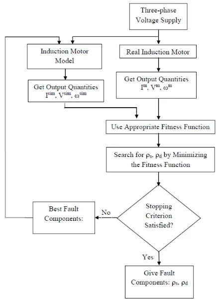
[image:3.595.312.547.413.517.2] [image:3.595.52.284.482.557.2]On the contrary, a model-based fault diagnosis approach can detect the exact degree of eccentricity fault. Model-based techniques came into contemplation in early 70’s and is still being progressed. The model-based methods are based on checking the consistency between actual measurements and the expected behaviour of process using its analytical models, Fig. 2. In a model-based approach, usually the fault indexes computed from the simulation model and actual measurements are subtracted to generate the residual values. These residual values are nothing, but the contribution of fault components present in the damaged motor. An induction motor model is nothing more than an exact replica of motor simulated under the equivalent power supply, control and loading condition. Almost 45 years have passed since the development of model-based techniques and still there are a lot of improvements which should be done to improve its reliability.
Fig. 2 Model Based Fault Diagnosis Approach
In [19], a model for the detection of fault in induction machine based on Digital Signal Processing (DSP) technique is proposed. The developed model can take decisions independent of the of motor’s operating conditions. In [20], the authors proposed a model-based technique namely Virtual Current Technique (VCT) for the correction of fault in direct rotor field oriented controlled induction motor for the diagnosis of rotor faults. A virtual magnetizing current is generated by measuring oscillations present in the direct axis component of rotor flux at a frequency double the slip frequency, to detect the rotor fault components in machine. Blodt et al. [21] detected the bearing fault by monitoring the stator current. A model is created in which variations due to air gap eccentricity fault are considered along with variations in load torque. Signals for torque, vibration and stator current are examined both for artificial fault and real fault for bearing
and the signals will detect and diagnose the fault.
In [22], a model was prepared by short-circuiting the inter-turns of windings using short circuiting elements to propose parameter estimation technique for the diagnosis of inter-turn short circuit fault in the stator of squirrel-cage induction motor. However, the key parameters were approximated in both online and offline mode to detect the fault. A model is simulated in [23] for faulty induction motor based on winding function theory, also known as MCCM to detect mixed eccentricity fault. A new linear model was proposed by using the current and voltage of stator from MCCM and by proper estimation of parameters of the linear model, mixed eccentricity fault was detected and diagnosed. In [24], eccentricity faults of squirrel cage induction machines was simulated dynamically using unified winding function approach. In [25][26][27], use of firefly algorithm is made for estimating the severity of static and dynamic eccentricity faults.
III. MULTIPLECOUPLEDCIRCUITMODEL Modified Winding Function (MWF) theory is used to calculate time-dependent self and mutual inductance for stator and rotor where MMF related spatial harmonics are taken into account [24][28][29]. As explained earlier, deviation of any of the axes (Os, Or, Ow) from the other two axes produce
non-uniformity in the air-gap and introduces eccentricity fault in the induction motor. Variations in the air-gap due to eccentricity are explained by the inverse air-gap function as follow:
(2)
(3)
(4)
where is healthy motor’s uniform air-gap length, angle for minimum air-gap length, angle for static eccentricity component, is degree of eccentricity, and are the degree for component of static and dynamic eccentricity.
(5)
where is the mean air-gap radius, is permeability of air, is stack length, is the angle in stator reference, is turn function for circuit. The , is modified winding function for circuit . Now considering 3- induction motor with phase a, b, c and rotor consisting of m meshes, the dynamic equations from multiple coupled circuit model are given by [28]:
(6)
(7)
(8)
(9)
(10)
(11)
(12)
(13)
(14)
(15)
(16)
(17)
where self/ mutual inductance matrix of stator phases, self/ mutual inductance matrix of rotor mesh, and are inductance matrix for stator phase and rotor mesh, and are the stator and rotor resistance matrices etc. The are the phase voltages of stator, are the currents in different phases of stator and are the flux linkages of different phases of stator. The are the currents
in each mesh of rotor, are the flux linkages
in each mesh of rotor. The are electrical torque and load torque, is moment of inertia, is speed of rotor and
angle for the position of rotor.
From the above equations the inductance for eccentric induction motor can be calculated for full range of degrees. This will make possible the simulation for healthy as well as for all types and degree of motor eccentricity conditions. The inverse air-gap function is defined, and an indefinite integral is calculated for obtaining the analytic equations for inductance. Also, the derivatives of this inductance equations with respect to angular position of rotor are calculated to obtain electromagnetic torque.
IV. METHODOLOGY
The proposed model-based fault diagnosis technique applied for diagnosing air gap eccentricity fault, continuously keeps an eye on the health of the motor. It continuously takes the data from the motor and keeps a check on whether the measured parameters are within the defined limits or not. From the Fig. 3, it is clear that the same 3- voltage supply is given to both the simulated motor model and real induction motor. Here, Isim, Vsim, ωsim are simulated values and Im, Vm,
ωm are measured values of current voltage and speed
respectively and s, d is degree of static and dynamic
[image:4.595.319.536.204.508.2]eccentricity.
Fig. 3 Flow chart for proposed methodology
Data for voltage, speed and current was acquired from both the simulated model and real induction motor, sampled and saved in the memory. This data was compared using a suitable objective function, given in expression (18). An intelligent algorithm was applied to search for the degree of static and dynamic eccentricity so as to minimise the objective function value. The above-mentioned procedure can also be applied offline by first acquiring the data from real induction motor and then, the feeding the acquired sampled voltage data to simulated model in order to get the signals for current and speed. Here, a firefly algorithm is applied for the search process using the fitness function:
where is the total number of samples taken, α is the weight factor is measured value for the stator current of phase a, is simulated value for the stator current of phase a.
Similarly is measured value for the stator current of phase b, is simulated value for the stator current of phase b and are the measured and simulated values for rotor speed. Constraints applied for the search of s and d are:
(19)
(20)
(21)
Since, is the limit of geometrical distance between rotor and stator, that’s why degree of static and dynamic eccentricity varies between 0 and 1. Although the value of static and dynamic eccentricity varies between 0 and 1, rubbing of stator and rotor was observed at at the time of experiment conduction.
V. FIREFLYALGORITHMIMPLEMENTATION
Firefly algorithm (FA) is one of the most recent algorithms developed for dealing with global optimization challenges and multimodal analysis. It has two inner loops for the population and one outer loop for iterations t. Therefore, the complexity of algorithm is . Since n is small and t is large, it is very economic to apply FA for computation as it is linear with respect to t. Also, due to the property of automatic sub-division, FA has an edge over other algorithms.
FA is based on the principle of movement of less shining firefly towards more shining firefly. It has the following set of rules:
Being unisex in nature, attraction of one firefly attraction of one firefly towards other is independent of sex. Since the glare decreases as the distance increases, less
glaring firefly will move towards more glaring firefly. If all the fireflies are equally glaring in their vicinity, then
they all moves randomly.
The movement of ith, firefly towards brighter jth firefly is given by:
(22)
where the second part is due to attractiveness and is given by:
(23)
[image:5.595.326.510.53.468.2]with is attraction at and the third part is due to randomization with as the randomization parameter and being a vector for random numbers drawn from either Gaussian or Uniform distribution.
Fig. 4. A Flow Chart For The Firefly Algorithm Used For Detection Of Components Of Eccentricity
Now the ith (i1, i2, i3….) firefly or jth (j1, j2, j3….) firefly represents the value of static or dynamic eccentricity degree. he fitness corresponding to each firefly can be assessed according to the optimization problem's proposed objective function. Each firefly's previously visited best position is considered its individual best position best denoted by . Similarly, for the whole group of flies the previously visited best position is noted as the global best position (gbest) and represented by G= (G1, G2, G3….). In each iteration, the position and the randomization factor [31] are updated according to expression (23). Write whatever you want here. Then press the Quill It button on the right to paraphrase it.
VI. EXPERIMENTALWORK
The nameplate ratings of motor given by the manufacturer are given in
Table I.
Table I. Nameplate Data Of Induction Motor
Specification Value Specification Value
AC/ DC AC Speed 1440
Power 0.5 HP Poles 4
Voltage 415 V Phases 3
Frequency 50 Hz Insulation class F
Current 1.15 A Power factor 0.75
Efficiency 94.7 % Degree of protection IP 55
[image:6.595.313.536.200.282.2]To induce eccentricity in induction motor, the healthy bearing with bearing number 6204 is replaced by another bearing with bearing number 6004 and proper bushing. This introduced static eccentricity fault in the motor. For generating dynamic eccentricity, the healthy bearing was replaced by 6005 bearing along with bushing. Fig. 5 shows the different bearings used for the experiment. Table II shows the dimensions of different bearings used for the experiment. In this way, different types and degree of eccentricity are induced in the motor to perform the experiment on healthy and eccentric motor. The data for stator line voltage, current and rotor speed are taken and saved in the memory.
Table II. Dimensions of different bearings used
Motor Condition
Bearing Number
Dimensions Inside
Diameter (mm)
Outside Diameter
(mm)
Width (mm)
Healthy 6204 20 47 14
Static
Eccentricity 6004 20 42 12
Dynamic
[image:6.595.57.280.407.659.2]Eccentricity 6005 25 47 12
Fig 5. Photograph Of Different Bearings Used For Eccentricity Fault Detection
An NI cDAQ-9178 data acquisition board was taken for acquiring the data. Data was acquired, sampled and saved in the memory of the personal computer. For the measurement of current, current transformer was used which will give the analog data as an output. This analog data was converted into digital form using DAQ card of type NI 9227 current input module and given to the computer.
For speed measurement, tacho-generator was mounted on the shaft of the motor which converts speed signal into voltage and give it to NI 9201 voltage input module. Similarly, for the measurement of voltage NI 9244 voltage input module was taken and data is given to the computer. To fetch the data from different DAQ cards LabVIEW software was used which saves the samples of current, voltage and speed into an excel sheet. The data for both the healthy and eccentric motor is acquired at a scan rate of 12800 samples per second. Simulink model is fed with the sampled data of stator voltage with the loading conditions on the motor remained unchanged as shown in Fig. 6.
Fig. 6 Simulink Model Of An Induction Motor For Eccentricity Fault Detection
VII. RESULTSANDDISCUSSION
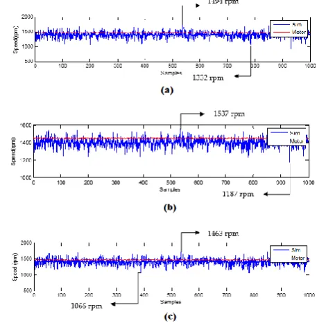
From Simulink model of induction motor to implementation of FA, all the calculations are done using MATLAB coding. Curves shown in Fig. 7(a), 7(b), 7(c) represents the measured and simulated speed for a motor with healthy, static eccentricity and dynamic eccentricity. The curves plotted in red color shows the measured speed whereas the curves plotted in blue color shows simulated speed of the motor.
[image:6.595.314.543.457.692.2]In Table III results are shown for degree of eccentricity and a comparison is made for both the simulated data and measured data with a motor in healthy condition, static eccentricity and dynamic eccentricity.
The column of “simulation results” shows the final degree of static and dynamic eccentricity obtained from the simulated model of induction motor and program code in MATLAB for different motor conditions. Similarly, the column of “measured results” shows the degree of static eccentricity and dynamic eccentricity induced in the real induction motor by replacing the healthy bearings with eccentric bearings.
Table III. Comparison between the degree of static and dynamic eccentricity
Condition of Motor
Simulation Results Measured Results
s d s d
Healthy 0.0194 0.0016 0.00 0.00
Static Eccentricity 0.10694 0.0137 0.1132 0.00 Dynamic
Eccentricity 0.00136 0.1279 0.00 0.1132
The degree of static eccentricity and dynamic eccentricity induced in the real induction motor by replacing the healthy bearings with eccentric bearings is 11.32% for both the cases. Also, the simulation results show that degree of static eccentricity s is 0.10694 or 10.694% and dynamic eccentricity is d as 0.0137 or 1.37% when bearings are replaced to induce only static eccentricity. Similarly, the degree of static eccentricity s is 0.00136 or 0.136% and dynamic eccentricity d is 0.1279 or 12.79% when bearings are replaced to induce only dynamic eccentricity. Small variations in simulation and measured results may be due to manufacturing defects, unbalanced magnetic pull when the motor is operating or due to centrifugal forces.
VIII. CONCLUSION
In this paper, MCCM based simulation was utilized to realize an actual induction motor with healthy and with different types of eccentricity fault conditions. From the simulated model the output of current and speed were taken and compared to the current and speed signals of real induction motor, acquired through different sensors. These measured and simulated signals were compared by using a specifically proposed fitness function which was minimised using FA to get an estimated degree of static and dynamic eccentricity.
The model-based fault diagnosis methodology adopted in this paper has yielded better results compared to the traditionally used signal based spectral analysis. The obtained results proposed that the fault detection methodology can accurately estimate the type and exact degree of eccentricity. Moreover, it has been found that the measured and the simulated results are in best agreement with each other. Hence, it can be deduced that the suggested model-based method is highly accurate and reliable for detection of eccentricity fault and can also be used to find similar types of faults in other types of motors. However, some inherent assumptions were made for deriving the model and thus, the applicability and reproducibility needs to be further investigated.
REFERENCES
1. Bouzid MBK, Champenois G. 2013 New expressions of symmetrical components of the induction motor under stator faults. IEEE Trans. Ind. Electron.60, 4093–4102. (doi:10.1109/TIE.2012.2235392)
2. Faiz J, Ojaghi M. 2009 Different indexes for eccentricity faults diagnosis in three-phase squirrel-cage induction motors: A review. Mechatronics19, 2–13. (doi:10.1016/j.mechatronics.2008.07.004) 3. Faiz J, Tabatabaei I. 2002 Extension of winding function theory for
nonuniform air gap in electric machinery. IEEE Trans. Magn.38, 3654–3657. (doi:10.1109/TMAG.2002.804805)
4. Faiz J, Ebrahimi BM, Akin B, Toliyat HA. 2009 Comprehensive Eccentricity Fault Diagnosis in Induction Motors Using Finite Element Method. IEEE Trans. Magn.45, 1764–1767.
5. Drif M, Cardoso AJM. 2008 Airgap Eccentricity Fault Diagnosis , in Three-Phase Induction Motors , by the Complex Apparent Power Signature Analysis. IEEE Trans. Ind. Electron.55, 18–22. (doi:10.1109/TIE.2007.909076)
6. Dorrell DG, Thomson WT, Roach S. 1997 Analysis of airgap flux, current, and vibration signals as a function of the combination of static and dynamic airgap eccentricity in 3-phase induction motors. IEEE Trans. Ind. Appl.33, 24–34. (doi:10.1109/28.567073)
7. Yahia K, Marques Cardoso AJ, Ghoggal A, Zouzou S-E. 2014 Induction motors airgap-eccentricity detection through the discrete wavelet transform of the apparent power signal under non-stationary operating conditions. Electr. Power Components Syst.42, 682–692. (doi:10.1080/15325008.2014.890966)
8. Ahmadi M, Poshtan J, Poshtan M. 2013 Static eccentricity fault detection in induction motors using wavelet packet decomposition and Gyration radius. 2013 1st Int. Conf. Commun. Signal Process. their Appl. , 1–5. (doi:10.1109/ICCSPA.2013.6487316)
9. Harihara PP, Kim K, Parlos AG. 2003 Signal-based versus model-based fault diagnosis-a trade-off in complexity and performance. IEEE Int. Symp. Diagnostics Electr. Mach. Power Electron. Drives, SDEMPED 2003 - Proc. , 277–282. (doi:10.1109/DEMPED.2003.1234586) 10. Hong J, Hyun D, Lee S Bin, Kral C. 2013 Offline monitoring of airgap
eccentricity for inverter-fed induction motors based on the differential inductance. IEEE Trans. Ind. Appl.49, 2533–2542. (doi:10.1109/TIA.2013.2264793)
11. Nandi S Sang Bin L.,Doosoo H. ITC. 2011 Detection of eccentricity faults in induction machines based on name plate parameters . IEEE Trans. Ind. Electron.58, 1673–1683.
12. Faiz J, Ojaghi M. 2009 Instantaneous-power harmonics as indexes for mixed eccentricity fault in mains-fed and open/closed-loop drive-connected squirrel-cage induction motors. IEEE Trans. Ind. Electron.56, 4718–4726. (doi:10.1109/TIE.2009.2030816)
13. Singh S, Kumar N. 2017 Detection of bearing faults in mechanical systems using stator current monitoring. IEEE Trans. Ind. informatics13, 1341–1349.
14. Faiz J, Ojaghi M. 2011 Stator inductance fluctuation of induction motor as an eccentricity fault index. IEEE Trans. Magn.47, 1775–1785. (doi:10.1109/TMAG.2011.2107562)
15. FERNANDEZ-CAVERO V, MORINIGO-SOTELO DM-S,
Duque-perez O, Pons-llinares J. 2017 A Comparison of Techniques for Fault Detection in Inverter-Fed Induction Motors in Transient Regime. IEEE Access5, 8048–8063. (doi:10.1109/ACCESS.2017.2702643) 16. Drif M, Marques Cardoso AJ. 2012 Discriminating the simultaneous
occurrence of three-phase induction motor rotor faults and mechanical load oscillations by the instantaneous active and reactive power media signature analyses. IEEE Trans. Ind. Electron.59, 1630–1639. (doi:10.1109/TIE.2011.2161252)
17. Kaikaa MY, Hadjami M. 2014 Effects of the simultaneous presence of static eccentricity and broken rotor bars on the stator current of induction machine. IEEE Trans. Ind. Electron.61, 2452–2463. (doi:10.1109/TIE.2013.2270216)
18. Ishkova I, Vitek O. 2015 Diagnosis of eccentricity and broken rotor bar related faults of induction motor by means of motor current signature analysis. Proc. 2015 16th Int. Sci. Conf. Electr. Power Eng. EPE 2015 , 682–686. (doi:10.1109/EPE.2015.7161130)
20. Cruz SMA, Stefani A, Filippetti F, Cardoso AJM. 2008 A new model-based technique for the diagnosis of rotor faults in RFOC induction motor drives. IEEE Trans. Ind. Electron.55, 4218–4228. (doi:10.1109/TIE.2008.2003365)
21. Blodt M, Granjon P, Raison B, Rostaing G. 2008 Models for bearing damage detection in induction motors using stator current monitoring.
IEEE Trans. Ind. Electron.55, 1813–1822.
(doi:10.1109/TIE.2008.917108)
22. Abdallah H, Benatman K. 2017 Stator winding inter-turn short-circuit detection in induction motors by parameter identification. IET Electr. Power Appl.11, 272–288. (doi:10.1049/iet-epa.2016.0432)
23. Nasiri, A, Poshtan, J, Kahaei MH. 2004 A New Scheme in Model-based Fault detection in Three-phase Induction Motors. Proc. IEEE Int. Conf. Machatronics (ICM ’04) , 19–24.
24. Faiz J, Ojaghi M. 2009 Unified winding function approach for dynamic simulation of different kinds of eccentricity faults in cage induction machines. IET Electr. Power Appl.3, 461–470. (doi:10.1049/iet-epa.2008.0206)
25. Yang XS. 2009 Firefly algorithms for multimodal optimization. Lect. Notes Comput. Sci. (including Subser. Lect. Notes Artif. Intell. Lect.
Notes Bioinformatics)5792 LNCS, 169–178.
(doi:10.1007/978-3-642-04944-6_14)
26. Sundareswaran K, Peddapati S, Palani S. 2014 MPPT of PV systems under partial shaded conditions through a colony of flashing fireflies.
IEEE Trans. Energy Convers.29, 463–472.
(doi:10.1109/TEC.2014.2298237)
27. Dos Santos Coelho L, Bora TC, Schauenburg F, Alotto P. 2013 A multiobjective firefly approach using beta probability distribution for electromagnetic optimization problems. IEEE Trans. Magn.49, 2085–2088. (doi:10.1109/TMAG.2013.2238902)
28. Ojaghi M, Mohammadi M. 2017 Unified Modeling Technique for Axially Uniform and Non-uniform Eccentricity Faults in Three-phase Squirrel Cage Induction Motors. IEEE Trans. Ind. Electron.46, 1–9. (doi:10.1109/TIE.2017.2760280)
29. Joksimović GM, Durović MD, Penman J, Arthur N. 2000 Dynamic simulation of dynamic eccentricity in induction machines - winding function approach. IEEE Trans. Energy Convers.15, 143–148. (doi:10.1109/60.866991)
30. Yang X. 2010 Firefly Algorithm.
(doi:10.1016/B978-0-12-416743-8.00005-1)
31. Yang XS, He X. 2013 Firefly Algorithm: Recent Advances and Applications. Int. J. Swarm Intell.1, 36. (doi:10.1504/IJSI.2013.055801)
AUTHORSPROFILE
Nikhil, was born on 1st October 1992 in Sirsa, Haryana.
He received his B.E. in Electrical Engineering from JMIT, Radaur, Haryana. He received his master’s degree in Instrumentation and Control Engineering from NITTTR, Chandigarh. He is serving as Faculty in Electrical and Electronics Department of UIET. Panjab University, Chandigarh. His areas of interest includes fault detection and diagnosis of induction motor, mathematical modeling, signal processing and optimization of parameters using bio-inspired algorithms.
Amandeep Sharma was born in Chandigarh, India
on 19 August 1984. He received his B.E. in Electronics and Communication Engineering from University Institute of Engineering and Technology (UIET), Panjab University, Chandigarh in 2007 and M.Tech. degree in Instrumentation from University Centre for Instrumentation and Microelectronics (UCIM), Panjab University, Chandigarh, India in 2009. He worked as a Junior Research Fellow (JRF) in Central Scientific Instruments Organization (CSIO), Chandigarh working under DST funded project from September 2009 to May 2011. He served for about two years as Assistant Professor, Instrumentation and Control Engineering (ICE) Department of Dr. B. R. Ambedkar National Institute of Engineering and Technology Jalandhar, Punjab, India from August 2011 to October 2013. Presently, he is pursuing his Ph.D. from Electrical Engineering Department, National Institute of Technical Teachers Training and Research (NITTTR), Panjab University, Chandigarh in condition monitoring of electrical motors. His research
interests include condition monitoring of electrical machines using statistical methods and machine learning algorithms, artificial intelligence-based computation and multi-agent classifier systems. He is particularly interested in analysis of non-stationary signals and model-based fault diagnosis. Mr. Amandeep Sharma is a Life Member of Indian Micro-electronics Society, IMS (India).
Navdeep Minhas, was born on 8th September 1996
in Hamirpur, Himachal Pradesh. He received his B.E. in mechanical engineering from Beant College of Engineering and Technology, Gurdaspur, Punjab. Presently he is pursuing his master’s in manufacturing technology from NITTTR, Chandigarh. His research problem includes the simulation and fault analysis of the ball bearings using Finite Element Analysis (FEA). He is particularly interested in fault detection and diagnosis and simulation of mechanical systems using FEA.
Arshdeep Singh was born in Dabwali, Haryana