On the way to driverless road-train: Digital
technologies in modeling of movement,
calculation and design of a road-train with
hybrid propulsion unit
Roman Dobretsov1, Matvey Gubachev1, Ivan Naletov 1*and Alexey Vasiliev1
1 Peter the Great Saint Petersburg Polytechnic University, Institute of Energy and Transport Systems, 195251 Polytechnicheskaya st. 29, Russian Federation
Abstract.Today, road-trains are one of the most widely-spread and multi-tonnage transport vehicles on road arteries interconnecting countries and cities. The concept of hybrid road-trains mostly meets the widely-spread policy for stepping up the rates of exhaust gas emissions and reducing specific hydrocarbon fuel costs but only an intermediate link in the development of more significant and important design – a driverless road-train. This article considers active trailers and their models with different design options for heavy tractor truck propulsion unit drive. The influence of trailer link drive on turning has been studied in "Universal gear" software. Special attention has been given to an electrical drive of active semi-trailer wheels as the most advanced one at the present moment. We have obtained the data intended to be used in design of active trailer chassis and identified the weight and size characteristics of energy accumulators required for movement of a road-train with active trailer. The efficiency factor for different semitrailer drives has been analyzed and calculated, in particular: Low EF of electrical drive. The relevancy of active trailer concept including that for driverless road-trains has been determined on the basis of received data.
1 Introduction
At the beginning of 1950th of the last century Soviet designer B.M. Fitterman offered a concept of active trailers. This idea consisted in supplying power from the tractor truck propulsion unit to the trailer or semitrailer wheels with by means of power mechanical drive. Thus, the first experimental model based on GAZ-63D chassis with additional power take-off box was built. Torque was transmitted by means of gearboxes and universal joint shafts. After tests it was possible to identify the weaknesses in design and standard assemblies in relation to high loads [1]. Road-trains with mechanically driven semitrailers were designed with success later, for example: GAZ-66K with single-axle semitrailers with mechanically driven wheels, tractor truck ZIL-157KV-1 with semitrailer PAU-3 for transport vehicle 9T22, truck-tractor MAZ-502V with single-axle active semitrailers,
*Сorresponding author: [email protected]
URAL-380 with active semitrailer Ural-862, KrAZ-E259 with active sided semitrailer E834, ZIL-157KV-1 with mechanically driven semitrailer wheels, NAMI-058S and semitrailer Ural-862, active semitrailer MMZ-881, KrAZ-260D and semitrailer MAZ-9382 with mechanical drive [1,2,3].
Apart from mechanical drive, a hydraulic drive was also used in road trains with active trailers, the power was transmitted as follows: Through the power take-off box some torque is transmitted to the hydraulic pump, from there some fluid through branch pipes goes to the hydraulic engine, then torque from this hydraulic engine through reducing gearbox or universal joint shaft is transmitted to the trailer driving axles. Examples of train roads with hydraulic drives: Special-purpose tractor truck ZIL-157V with hydraulically driven wheels of semitrailer MMZ-584, ZIL-137 with hydrostatic drive [1].
The book [1] mentions a road train with electrical drive of driving wheels:
“The first road train with electrical drive of driving wheels was designed in 1959 in the USSR under the supervision of G.I. Bazylenko, no less original design with hydraulic came to light the next year. The authors of this article could not find any photographs or additional information about this road train with electrical drive. The options of operation with electrical drive are described in papers [4] and [5]. Paper [4] offers a self-contained propulsion system to be used as an option or simple engine power take-off by means of power take-off and generator. The authors have shown a hybrid drive scheme in paper [5].
Today, the concept of active road train acquires a new life as part of design basis to develop a national driverless road train. Road trains with active trailers or semitrailers, apart from anything, are provided with high cross-country capacity and can be used in both in the Far North conditions and in the timber and oil and gas processing industries.
The purpose of this work is to calculate parameters (weight and size) of power storage units to allow an active trailer run in continuous mode (for further consideration of their influence on the characteristics of road train), EF analysis for different drives of active semitrailers and the influence of an active trailer on the whole road train movement by means of up-to-date software.
The research methodology consists of: theoretical part (a comparative analysis of technical solutions on the basis of system-wide approach), analytical approach to identify design features for active trailers with electrical drive, studies and comparisons of stability when a road train with passive and active trailer links making a turn in “Universal mechanism” software complex.
The use of an active trailer link will make it possible to enhance the cross-country capacity of a road train in heavy road conditions and increase an average traffic speed over general purpose roads and make it more self-sustained, which is relevant for the concept of off-road driverless road trains. The negative side of this approach is that the road train design (in particular –a trailer) is made more complex and its weight and production costs are increased. Therefore, it seems to be important that apart from a comprehensive analysis of technical usage aspects of active trailers [5], it is necessary to get a conclusion from logistics experts in this region on the practicability of these machines give the local features of road networks.
The cross-country capacity is improved by increasing the road train’s adhesive weight and the average speed is increased by reducing the risk of drifting during maneuvers. The last property to the full extent makes it possible to implement an active trailer with traction electric motor drive (TEM) controlled by an electronic control system. The aspects of improving the road train's efficiency and reducing harmful emissions are of concern as well [5].
2 Selection of parameters for energy accumulators of road train
with active trailer
Let us calculate the energy costs and evaluate power spent to overcome external obstacle trailer movement within a road train. A timber road train based on tractor truck Ural 43204-1111-41 and double-axle timber drag trailer 904712 designed to transport clean wood and logs up to 23 m long over all types of roads and terrain was taken as a prototype. The loaded trailer’s maximum weight is 4500 kg, the timber drag trailer’s lifting capacity is 7200 kg and the weight of transported cargo is 16000 kg [6]. Engine YaMZ-236 installed on the trailer provides the traction forces required to make the road train move.
The resistance forces are calculated only with due consideration of weight acting on the road train's trailed link being equal to:mп=11700 kg.
The speed effect on the factor of rolling resistance is taken into account according to formula 1 [7]:
2
0 1 0.0216
f f v , (1)
Where f0 is the factor of rolling resistance at low speeds; vis the road train’s speed, m/s. These resistance forces are calculated without a road slope that is why dependence 2 has been used:
tr
P f m g , (2)
Where mtris the trailer’s weight, f is the factor of rolling resistance with speed.
When the road train moves at a low speed the influence of aerodynamic forces can be neglected. In transport mode the effects of aerodynamic forces are already significant, that is why let us calculate the aerodynamic forces according to dependence 3 [7]:
2 ρ / 2 w
P c Fv , (3)
Where c is the factor of aerodynamic resistance; ρ is air density kg/m3; Fis the vehicle’s frontage area, m2; v– is the road train speed, m/s.
[image:3.482.55.428.499.639.2]In order to find the required energy (and consequently, travel resistance power), let us make an evaluative calculation for typical road conditions. ThecalculationresultsaregiveninTable 1. The received data are used to select a traction electric motor, the parameters of energy accumulators and to resolve the issues of equipment layout on the trailer.
Table 1. Power, energy characteristics of travel resistance.
Road conditions Travelspeed , m/s
Travel resistance force, kN
Specificenergy,
MJ/h Specificpower, kW/h
Systematic travel: earth
road (f0 = 0.025) 5 6.71 120.72 33.53
Heavy conditions: water-logged unpaved run
(f0 = 0.25) 2 34.01 244.90 68.03
Transportmode:asphalt
(f0 = 0.01) 12 6.68 288.74 80.21
Using the received calculation data on the road train travel resistance forces, let us select the parameters for energy accumulators determining the peculiarities of its layout on a transport vehicle.
The traction electric motor (TEM) and energy accumulators fitted on the trailer will require a more powerful generator. It is also expedient to consider the issue of increasing the on-board voltage at least within the TEM feed system, which will make it possible to significantly reduce the weight and size characteristics of these electrical machines. In addition, for further reduction of TEM sizes, it is expedient to provide a double-mode reducing gearbox with automatic control.
The most advanced type of energy accumulators now is electric double-layer capacitor (capacitors with double electrical layers), because this type of electrical device can handle high amounts of stored energy and discharge power with relatively high EF value (at the present moment, electric double-layer capacitor fed buses are manufactured by HyundaiMotor,Trolza, Belkommunmash [8]).
For the purpose of calculation we have used the energy accumulators with electric double-layer capacitors К58-20. Specific discharge power of electric double-layer capacitors К58-20 with matched load is 1.0 kW/kg, 1.5 kW/dm3 [9].
Based on the need to provide power input equal to33.53 kW/h (without wiring resistance), let us to evaluate the accumulator’s weight [9]:
mр.dlc. η ηTEM
з acc
н
W m
W
, (4)
Where ηacc=0.85 is the accumulator’s EF; ηtem=0.9is the traction electric motor’s EF; Ws is the spent specific power kW/h; Wmр.dlc.is the specific discharge power of electric double-layer capacitors, kW/kg.
Accordingly the accumulator's volume (approximately) [9] is calculated as per dependence 5:
TEM
. . η η
acc
Vр dlc acc
W s V
W
, (5)
Where ηacc=0.85 is the accumulator’s EF; ηtem=0.9is the traction electric motor’s EF; Ws is the spent specific power kW/h; Wmр.dlc.is the specific discharge power of electric double-layer capacitors, kW/dm3.
In such a manner, in order to overcome the trailer’s rolling resistance over an earth road (most typical conditions for timber industry) at a speed of 5 m/s (18 km/h) it is necessary to ensure that a capacitor battery unit up to 43.8 kg in weight and 29.3 dm3 (0.028 m3) in area is installed.
According to the labor safety and driver’s rest regulations and working hours allowed for them (not more than nine hours) let us evaluate the weight and volume of accumulator to be equal to 394.2 kg and V=0.260 m3 in an approximate way.
It should be noted that the trailed link activation is not intended for continuous operation. The trailer's drive should be activated in heavy road conditions requiring this, during uphill movement etc. Moreover, the TEM can be used en-route to stabilize the trailer during maneuvers.
The first option for accumulator layout seems to be safer. The second option for accumulator layout is more favorable in terms of active trailer’s reliable operation (loss of accumulator-to-generator connection is less critical than that of TEM-to-accumulator connection).
Using the received calculation data on the road train travel resistance forces, let us select the parameters for energy accumulators determining the peculiarities of its layout on a transport vehicle.
The traction electric motor (TEM) and energy accumulators fitted on the trailer will require a more powerful generator. It is also expedient to consider the issue of increasing the on-board voltage at least within the TEM feed system, which will make it possible to significantly reduce the weight and size characteristics of these electrical machines. In addition, for further reduction of TEM sizes, it is expedient to provide a double-mode reducing gearbox with automatic control.
The most advanced type of energy accumulators now is electric double-layer capacitor (capacitors with double electrical layers), because this type of electrical device can handle high amounts of stored energy and discharge power with relatively high EF value (at the present moment, electric double-layer capacitor fed buses are manufactured by HyundaiMotor,Trolza, Belkommunmash [8]).
For the purpose of calculation we have used the energy accumulators with electric double-layer capacitors К58-20. Specific discharge power of electric double-layer capacitors К58-20 with matched load is 1.0 kW/kg, 1.5 kW/dm3 [9].
Based on the need to provide power input equal to33.53 kW/h (without wiring resistance), let us to evaluate the accumulator’s weight [9]:
mр.dlc. η ηTEM
з acc н W m W
, (4)
Where ηacc=0.85 is the accumulator’s EF; ηtem=0.9is the traction electric motor’s EF; Ws is the spent specific power kW/h; Wmр.dlc.is the specific discharge power of electric double-layer capacitors, kW/kg.
Accordingly the accumulator's volume (approximately) [9] is calculated as per dependence 5:
TEM
. . η η
acc
Vр dlc acc
W s V
W
, (5)
Where ηacc=0.85 is the accumulator’s EF; ηtem=0.9is the traction electric motor’s EF; Ws is the spent specific power kW/h; Wmр.dlc.is the specific discharge power of electric double-layer capacitors, kW/dm3.
In such a manner, in order to overcome the trailer’s rolling resistance over an earth road (most typical conditions for timber industry) at a speed of 5 m/s (18 km/h) it is necessary to ensure that a capacitor battery unit up to 43.8 kg in weight and 29.3 dm3 (0.028 m3) in area is installed.
According to the labor safety and driver’s rest regulations and working hours allowed for them (not more than nine hours) let us evaluate the weight and volume of accumulator to be equal to 394.2 kg and V=0.260 m3 in an approximate way.
It should be noted that the trailed link activation is not intended for continuous operation. The trailer's drive should be activated in heavy road conditions requiring this, during uphill movement etc. Moreover, the TEM can be used en-route to stabilize the trailer during maneuvers.
The first option for accumulator layout seems to be safer. The second option for accumulator layout is more favorable in terms of active trailer’s reliable operation (loss of accumulator-to-generator connection is less critical than that of TEM-to-accumulator connection).
Thus, when the accumulator and TEM are located on the trailer the spring-suspended weight of the latter will increase by 400 kg approximately. The received data is intended to
be used in design of trailer’s chassis, the concept of which is considered in detail in paper [5].
3 Calculation of efficiency factor for active trailer drives
It is necessary to analyze the active trailer drive for efficiency factor. A mechanical drive is simple in design and has low weight and a universal-joint drive is used for power transmission. The drive's EF reduces due to a bigger length of this universal-joint drive.
The mechanical drive’s EF is calculated for the accepted scheme as per dependence 6:
4 2
м de sgb tgb b ujd
η η η η η η , (6)
Where еηde 0.35 is the diesel engine’s EF; ηgb 0.85 is the speed change gearbox’s EF;
tgb
η 0.99 is the transfer gearbox’s EF; ηр 0.97 is the bevel gear’s EF (4 gearboxes);
к
η 0.95 is the universal-joint drive’s EF with a big distance between the gearbox and drive axles taken into account. Thus, ηм 0.235.
It should be noted that when such road train turns the kinematic incompatibility of drives has a negative effect on the whole road train's movement .The issue of this kinematic incompatibility is still open [1, 10, 11].
The use of hydrostatic drive makes it possible to get rid of geared and universal-joint drives. The trailers with hydrostatic drive are designed using the “hydraulic shaft” or “hydraulic motor-wheel” principle [10].
Hydraulic units make it possible to run at low RPM. The hydraulic motor-wheel’s RPM based on a limit speed is equal to [10] as per dependence 7:
. 0 0.377 rt v n r
, (7)
Where n is revolutions, r/s; v is the road train's speed, m/s; r0 is the tire radius along its central part, m.
Here we get to know that when unit 11МNo20 with maximum permissible shaft revolutions equal to 1440 RPM is used (this hydraulic unit was used on road train ZIL-137), the maximum travel speed with a radius of tires equal to 0.6 m is 5.4 m/s with hydraulic drive used without an extra step-up gearbox.
The trailed link drive is on road train ZIL-137 is turned on only when heavy road sections are to be negotiated with hill-climbing, first and second gears engaged [1, 10].
The hydraulic drive’s EF with the parameters of other drives was not compared as there is an acute shortage of information about hydraulic drive systems and their application is limited and intermittent in trailers due to the above-mentioned reasons.
The trailer’s electrical drive is the most promising one at this moment [5].The electrical drive has a number of advantages: simple power feed, good traction performance, possible power flow redistribution depending on travel resistance [10].
According to the accepted scheme as per dependence 8 the following results are received
e de tgb а tem rec drive gen
η η η η η η η η , (8)
Where ηde 0.35 is the diesel engine’s EF; ηtgb 0.99 is the transfer gearbox’s EF;
а
η 0.85 – is the accumulator’s EF during charge/discharge; ηtem 0.9 is the traction electric motors’ EF; ηgen 0.9 is the generator’s EF; ηdrive 0.99 is the drives’ EF;
rec
η 0.93 is the rectifiers’ EF [12]. Numeric value of the electrical drive’s EF ηe 0.22. It is possible to call this option for evaluating the electrical drive’s EF pessimistic: While calculating the electrical drive’s EF it has not been taken into account that some energy is recovered; the minimum EF values of serial units and devices have been used. Due to an electric double-layer capacitor the electrical drive’s EF may turn out to be slightly less than the mechanical drive, however, due to the electrical drive's capabilities make it possible to control the active trailer's wheel in an individual manner. Statistical and experimental data are required to calculate and estimate the drives for efficiency.
4 Road train motion analysis
[image:6.482.61.411.243.380.2]Two road trains with active and passive trailed links have been compared in “Universal mechanism” software using a special automotive modeling module “Automative” (Fig. 2, 3) show time-based turn side-slip angle dependence.
Fig. 1. 3D visualization of a turn:1 – direct movement, 2- fast turn of a tractor truck, 3- swinging of a trailer, 4 – stabilization of a trailer
rec
η 0.93 is the rectifiers’ EF [12]. Numeric value of the electrical drive’s EF ηe 0.22. It is possible to call this option for evaluating the electrical drive’s EF pessimistic: While calculating the electrical drive’s EF it has not been taken into account that some energy is recovered; the minimum EF values of serial units and devices have been used. Due to an electric double-layer capacitor the electrical drive’s EF may turn out to be slightly less than the mechanical drive, however, due to the electrical drive's capabilities make it possible to control the active trailer's wheel in an individual manner. Statistical and experimental data are required to calculate and estimate the drives for efficiency.
4 Road train motion analysis
Two road trains with active and passive trailed links have been compared in “Universal mechanism” software using a special automotive modeling module “Automative” (Fig. 2, 3) show time-based turn side-slip angle dependence.
Fig. 1. 3D visualization of a turn:1 – direct movement, 2- fast turn of a tractor truck, 3- swinging of a trailer, 4 – stabilization of a trailer
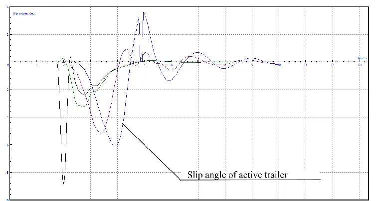
[image:7.482.54.432.72.274.2]The context of this simulated experiment is that the road train at selected speed V0 then a sharp jerk of the steering wheel occurs, which results in swinging of the trailer (Fig.1). Fig. 2 and 3 show that the road train with active drive has higher slide-slip angles during turn, which should have a negative effect on this road train’s stability.Also, within an interval of 4.7-5 s on the chart it is possible to see a sharp decrease in sideslip angles down to zero with a further increase (see Fig.2).
[image:7.482.61.432.304.531.2]Fig. 2. Time-based sideslip angle dependence: turning of road train with active trailer.
Fig 3. Time-based sideslip angle dependence: turning of road train with passive trailer.
A break on the chart is related to lift-off of the active trailer's wheels from the surface. Probably the wheels lift off due to power feed to the wheels. At the same speed within the given time interval the road train with passive trailer has no loss of stability (see Fig.2, 3).
Time-based roll and yaw angle dependencies of the trailers with active and passive trailed links are close in shape and differ slightly in amplitude values.
5 Conclusions
The data received as a result of calculations and digital modeling bring us to a conclusion on how it is important to conduct a more serious software-aided and digital modeling, which will form a basis for practical experiments and help to develop a full process picture of how the road train with active and passive trailer, which is expedient to be used as a basis for the development of driverless road trains, moves. The analysis of results shows that it is required to increase the roll stiffness of suspension for trailers with electrical drive, which is important to consider in design of this type transport means.
We have indentified the need to develop an automatic TEM control system, which will make it possible to counteract the above-mentioned sideslips of trailer's wheels, reduce the road train's yaw angles as a whole; it is expected that this system can be used as a road train stabilization system and provide kinematic compatibility of links.
Modern technologies allow going back to the concepts of a road train with active and passive wheels; in this case it is possible to make design structures, whose operation is justified in a great number of life activities.
At this moment, the design of active trailers is a very interesting task that needs to be resolved, first of all, in electronic format, because the modern design capabilities make it possible to a greater extent of accuracy to simulate any structure, mechanism or design as well as different events involving them, which will greatly reduce capital costs during design of equipment and simplify the development and testing process for invented equipment. The use of hybrid schemes with possible energy recovery on vehicles is the most challenging and has a huge potential to save fuel saving and reduce atmospheric emissions with keeping and even increasing the vehicle’s self-sustainability as a transport means [12].
The principle of hybrid drive with a “motor-semi-axle" pattern for driving the trailer's drive wheels from an electric motor [14] is the bases of the concept. The development of more perfect wheel drives remain to be important and relevant issues [11] to allow road trains [15] to have a more improved cross-country capacity and maneuverability. One of the possible forms for developing the concept of hybrid road trains with proposed scheme can be a driverless road train, whose design basis will be formed by the results of conducted research, calculations and modeling.
References
1. E. Kochnev, Secrete motor vehicles of the Soviet Army (Yauza, Eskmo, Moscow, 2001)
2. KrAZ-260D History of the vehicle development [online]. Available at: http://zazsila.ru/news/2012-08-23-155 (2018)
3. Mytichinsky machine-building plant MMZ-881 [online], Available at: http://denisovets.ru/mmz/mmzpages/mmz881.html (2018)
4. V. Gorelovet al., N.E.Bauman, MSTU. Digital magazine, 12 (2016)
5. А. Vasiliev et al., Proceedings of scientific conference with international participation.
(Publishing house of Polytechnic University,Saint Petersburg, 2017) 6. Timber truck Ural with self-loading trailer[online], Available
at:http://www.sibpromtrans.ru/les/les_samopogruz.php (2018)
7. V. Tarasik, A theory of vehicle movement (BXV-Petersburg, Saint Petersburg, 2006) 8. Electrobuses [online], Available at: https://bkm.by/catalog/elektrobusy (2018)
9. Electric double-layer capacitors (ionistores)[online], Available at: http://www.elecond.ru/kondensatory_ionistory.php (2018)
10. M. Zapryagaev et al., Army vehicles. Design and calculation (Voenizdat, Moscow,1970)
11. Ya. Zakinet al., Designs and calculation of road trains(Publishing house “Machine building”, Leningrad, 1968)
12. V. Gaevsky, I. Odinokova, Scientific and technical magazine “Automotive industry”(2017)
13. R. Dobretsov et al., Proceedings of scientific and practical conference “Development and usage of electrical transmission systems for military equipment (JSC
VNIITransmash) (Publication of JSC VNIITransmash, Saint Petersburg, 2016) 14. А. Vasiliev et al., Proceedings of scientific conference with international participation.
Publishing house of Polytechnic University(2017)
15. А. Vasiliev et al., Proceedings of scientific conference with international participation (Publishing house of Polytechnic University, Saint Petersburg, 2017)