Abstract: Data compression techniques are explored in this paper, through which system memory size gets reduced in an effective manner. The size of the memory is always a key constraint in the embedded system. Larger memory size increases the bandwidth utilization which raises the cost of hardware and data transmission. It is difficult to transfer large data through the network. Data compression encoding technique is utilized to minimize the data size. The redundant character is reduced or encoding the bits in data is done to reduce the data size. The proposed system focused on lossless compression where the original information of the data is available even though the data size is compressed. The data compression is done through a dictionary-based compression algorithm and Alternating Statistical Run Length code (ASRL). In the existing system of ASRL, the compression ratio is about 65.16% and 67.18% for two benchmark circuits S5378 &S9234. The compression ratio of the test data is increased by combining the ASRL and Improved Dictionary-Based compression Technique. The proposed combined technique provides 80.25%& 82.5% compression ratio for two benchmark circuits S5378 &S9234. This reduces the power dissipation problem in the circuit and thereby the area of the circuit gets reduced.
Keywords: Improved Dictionary Based compression Technique, ASRL, ALE, UML.
I. INTRODUCTION
Memory plays a vital role in the embedded system where it decides the circuit area, power dissipation, and cost. Data compression is the method of encoding the input data with lesser bits without loss of information. The two categories of data compression are lossless and lossy compression. In lossless compression, the data is compressed and the data size is reduced without modifying or losing the original information. Normally text files are compressed under this category. In lossy compression, there is a difference between the compressed and original data. Images and audio are tested for compression through this technique. The original input data can’t be restored if the test data is compressed. But the compression ratio is higher than lossless compression. The lossless data compressions are Run-length encoding, Shanno-Fano coding, Huffman Coding and Arithmetic Coding.
Revised Manuscript Received on Aug 22, 2019
S.Anandhi, Research Scholar, Electrical Engineering Department, Annamalai University, Chidambaram, India.
R.Neela, Professor, Electrical Engineering Department, Annamalai University, Chidambaram, India.
M.Janaki Rani, Professor, Electronics and Communication Engineering Department, Dr.M.G.R. Educational and Research Institute, Chennai, India.
[image:1.595.308.539.287.421.2]In Embedded design, the designers mostly concentrate on the size of the chip/circuit. They mostly tried to reduce the size of the circuit by using Automatic Test Equipment (ATE) to store the test data. The size of the circuit also depends upon the memory of the system. This has made memory as the key constraint for processing. Power dissipation problem is caused as the ALE loads the data into chip where switch transition takes place during test mode.
Fig. 1 Test Data Methodology
The above block diagram shows the conventional test data compression the original data get compressed through an algorithm and is stored in memory. After that, the test data is retrieved from the memory and decompressed and transfer to the Device Under test Circuit (DUT) which is depicted in figure1. The formula for compression ratio is given below.
Compression Ratio =
--- Equ. (1)
In the Dictionary compression method, the instructional sequences get stored in the dictionary. Recently some techniques are proposed which enhance the dictionary compression method to the next level by analyzing the mismatches in the sequences. Thus by changing the bit position, it can reduce the data code. Sometime during the compression techniques, the system performance may get affected. So it is a typical task to select the compression technique which reduces the code into substantial code and avoid the decompression penalty (not affecting the system performance). An efficient code compression technique is proposed that improves compression ratio by combining the Improved Dictionary-Based Compression Technique and Alternating Statistical Run Length Scheme. The paper organization is as follows; Section II discusses the related work of the system. Section III explains the concept of Improved Dictionary based compression technique, and
Efficient Test Data Compression for SoC
through ASRL with Improved Dictionary based
Compression Technique
S.Anandhi, R.Neela, M.Janaki Rani
Test Data Compression Algorithm
Compressed data (memory)
alternating statistical Run Length scheme. Section IV discusses the proposed system and Section V deals with the results and discussions. Section VI discusses the conclusion.
II. RELATED WORK
Li et al. [1], proposed a method for analyzing the compression ratio where test data get compressed using dictionaries which are selective with fixed length indices. The data transmission is taking place through a small ATE channel. It provides a good handshaking approach between the ATE and SOC. The compression ratio is higher than the Huffman coding with variable indices' compression ratio. Rhen et al.[2], compares the Huffman and the LZW algorithm for data compression where images, audio, and text file are analyzed for measuring the compressed ratio by these algorithms. Through which, it is understood that the Huffman algorithm provides better compression for text files and audio files where LZW algorithm compression time for the image is less.
Alireza et al. [3], proposed a paper for data compression through the deflate algorithm where 3.39% of the compression ratio is achieved on an average. Raja et al. [4] propose a novel method for reducing the power dissipation during the examination of VLSI in the testing field. The power dissipation occurred due to the switching transition in the system. By LPT-X filling methods, the system achieves 83% of reduced power dissipation during testing. Komal et al. [5], analyzed the performance and efficiency of various lossless data compression techniques. Gonciari et al. [6] presented a new way for embedded core-based system on chip compression techniques. In this approach, analyze some parameters such as time, area overhead and compression ratio. Sanjay et al. [7] proposed a method to analysis the fault dropping on Huffman based test data compression technique. Yuvan et al. [8], enhance the compression ratio by count compatible pattern run length coding compression method. It analyzed by six largest ISCAS’89 benchmark circuits and achieved a 71.73% compression ratio. Kumar et al [9], proposed a 2n- PRL compression method for data compression. Through their theoretical calculation, it is understood that the code word length can be reduced which increases the compression ratio. Ajmal et al [10], proposed a compression method to reduce the memory requirement and testing time. In this method, evaluation takes place by the combination of Dictionary compression method and bitmask selection. It contributes on reducing the code size which increases the embedded system functionality. It utilizes bitmask selection and efficient dictionary which significantly reduce the time and memory requirement.
Kumar et al. [11], analyzed the compression technique through Huffman code, in order to reduce the channel bandwidth and storage size. ASIC and FPGA methodologies are used for designing the system. Shilpa et al. [12], presented the entropy encoding algorithm for lossless compression technique by binary tree method. Seo et al. [13], proposed a paper for compressing the test data through dictionary-based compression which provides a 65% compression ratio. Wolfe et al. [14], tried compression technique using the Huffman code where the main memory
holds the compressed code. A decompression unit is placed n between the memory and instructional cache.
Wolf et al. [15], compress the data using the arithmetic and Markov model. In Lekatsas et al. [16], the data is compressed using dictionary-based compression. In this method, the data get decoded per cycle in the system. After a few years, some researchers found a way to decode multiple instructions per cycle [17]. Liao et al.[18], proposed a method for reducing the cost of the DSP circuit. Hemaraj et al. [19], reduce the concurrency of the input file through the LZ77 data compression Algorithm. Rosienger et al [20], tried to save the power up to 97% on SOC. Ruan et al.[21], reduce the volume of test vector which gets automatically stored in automatic test equipment (ALE). Yuan et al.[22], propose a method to reduce the power dissipation using alternating statistical run-length coding (ASRL). The test set data of this method undergone the preprocessing stage where testing and verification is done. After that, it filled with don’t care bits in it. But it suffers from area overhead in SOC. To overcome this hindrance, the system can be combined with the Advance dictionary-based compression approach. Paper [23] has Proposed a technique which is a combination of the bit mask dictionary and 2nd pattern run length-coding method improves the efficiency of compression without adding any penalty in decompression.
Count Compatible pattern Run-Length(CCPRL)
compression method has been proposed in [24]. A part of test pattern is retained from the test pattern set as the first step. In the second step, don’t care bits are filled so that the subsequent test patterns are made compatible with the patterns that are retained in the first step. As the third step, the compatible patterns (equal attends) are represented as ‘0’ and contrary patterns are represented as ‘1’ in the codeword. An improved bitmask selection technique is proposed for test data to achieve maximum pattern matching [25]. It used the combination of both dictionary and bitmask selection technique which has efficiently reduced the memory requirement and testing time. System-on-a-chip compression technique is combined with alternating statistical run-length coding is proposed in [26]. Preprocessing of test data is done using 2D reordering scheme. 4m partitioning for runs and filling of don’t care bits greatly improves the compression ratio. A flexible run aware PRL is proposed in [27]. 2n runs of inversely compatible or compatible is iteratively coded by the external N-PRL coding technique. This achieves the higher compression ratio and reduced test application time.
The compression efficiency is enhanced without adding any decompression penalty.
[30] Presents a new run length compression technique which encodes the 2n runs either inside or across test data segments. An Optimal Selective Count Compatible Run Length coding is proposed in paper[31] to achieve maximum data compression against reduced test cost. It is a hybrid techniques using both 10 Coded run length(10 CPRL) and Selective CCPRL(SCCPRL) techniques. In this method, the complete data is segmented into blocks of data and compression is carried out using intra and inter block level merging techniques. For encoding, SCCPRL is used and 10CPRL is used for decoding at sub block levels. In case of no matching found at the block levels, then the pattern is retained along with the categorization bits.
Paper [32] aims at achieving high compression ratio through Augmented Recurrence Hopping based Run Length coding. The group code based test vector is compared with its duplicates. Volume of data sequences are reduced along with its memory requirement. In paper [33], a novel and hybrid X-filling and compression technique which has two stages of compressions for digital circuits is proposed which greatly reduces the power consumption and data volume. Modified 4m filling is combined with adjacent filling techniques to reduce the switching activities. Unspecified bits found in the test cubes are divided by the multiples of four which increases the correlation among the test data patterns. Two stage compression techniques are used to encode the filled test cubes.
III. EXISTING WORK Alternating Statistical Run Length scheme
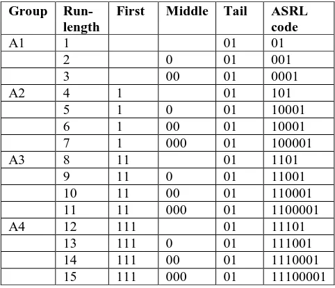
[image:3.595.306.551.190.277.2]The alternating statistical run-length scheme is a variable-variable run length code. Let A1, A2, A3, A4 are the four groups and the code is split into first, middle and tail. The first code represents the position of the run length code in the group. Here every 1 represents the 4bits of 0 or 1s. The middle codes the number of 0’s represent the remaining run length code in the group. The tail code is expressed as 01. At last the ASRL code can be created from these combinations.
Table. 1 Alternating statistical run-length code [22]
Group Run-length
First Middle Tail ASRL code
A1 1 01 01
2 0 01 001
3 00 01 0001
A2 4 1 01 101
5 1 0 01 10001
6 1 00 01 10001
7 1 000 01 100001
A3 8 11 01 1101
9 11 0 01 11001
10 11 00 01 110001
11 11 000 01 1100001
A4 12 111 01 11101
13 111 0 01 111001
14 111 00 01 1110001
15 111 000 01 11100001
[image:3.595.312.539.449.695.2]The Table.1 states that the first group assigns value 1s. The middle value gets decreased by each bit. The tail value is assigned as 01, so the ASRL code for the first group is assigned as 01, 001, 0001. After this, the ASRL Code gets divided based on the group. For each 4th run-length, 1 is combined with each bit. In the 1st section, 1 is assigned as 01and 00 is assigned as 001. In the 3rd section, the 6 run length code is divided into subsections where 4 bit of 0 is assigned as 1 and 2 bit 0 is assigned as 00, takes place in the 4th section. And the 1 is assigned as 01 which is tabulated in Table 1.
Fig. 2 Encoding Example
In figure 2, the conversion of test patterns into ASRL code is explained with an example. The Test pattern is about 18 bits which is coded based on the ASRL code. The MSB and LSB bit belongs to Group A1. The bits from 4th to 8th belong to Group A2. The next set of bit belongs to Group A3.
Dictionary-Based Compression
Dictionary-Based data Compression provides an advantage of both compression efficiency and fast decompression mechanism. It replaces the long substring with the variable length code. It commonly stores the instructional sequences which occurred in the process.
Input code Compressed Data (Compredded-0 Uncompressed – 1)
00000000 0 0
01001000 1 01001000
00011000 1 00011000
00100010 0 1
10000000 1 10000000
00011100 1 00011100
00100010 0 1
00111100 1 00111100
01000000 1 01000000
00000000 0 0
Fig. 3 Dictionary-Based Compression Technique [25]
Dictionary Index content
[image:3.595.48.289.577.784.2]The frequently occurring words are switched with code which represents the dictionary index, where the word is already stored. The string is replaced with the short variable length code in order to reduce the memory size. The compressed data is the constituent of a code word and uncompressed data. For example, a binary data consists of an 8-bit pattern, (i.e.) a total of 80 bits. The dictionary consists of totally two 8 bits (i.e.) 16 bits, the compressed data requires 62 bits. This is an example of variable length encoding. The technique is explained and illustrated in figure3.
Improved Dictionary-Based Compression Technique (Improved DBCT)
In this concept, the algorithm gets improvised by considering the mismatches. The mismatches occur due to the position of the instructional sequences in a few bit positions (Hamming distance). Finally, the compressed data’s are stored in the memory which is depicted in figure4.
Uncompressed code (Format) Decision
(1-bit)
Uncompressed data (32 bits)
Format for Compressed Data Decisi
on (1- Bit)
Number of bit changes /toggles
Locatio n (5 bits)
… …
Locatio n
(5 bits)
Dictionar y Index
[image:4.595.376.473.52.109.2]|--Extra bits for considering Mismatches ----|
Fig. 4 Encoding Format for Improved DBCT [25] The compressed data size depends upon the number of bit position. From figure 5, the compressed data can be easily matched with the index value of the dictionary. For example in the figure.5 the data code 00000010 is a compressed one whose bit position is matched by adjusting the position of the original data where mismatch value is 110.
The Dictionary-Based approach has some condition to select the compressed or uncompressed data. They are
1. If the MSB bit is 1, the data is uncompressed one and vice versa
2. If the data has consecutive one’s then the data is in uncompressed format.
3. Based on the dictionary value, the compressed and uncompressed data was declared.
Input code
Compressed Data
Mismatch Position
00000000 0 1 0
10000010 1 1 10000010
00000010 0 0 110 0
01000010 0 1 1
01001110 1 1 01001110
01010010 0 0 011 1
00000110 1 1 00001100
01000010 0 0 1 1
11000000 1 1 11000000
00000000 0 0 1 0
Fig. 5 Improved Dictionary-Based Compression Technique[25]
IV. PROPOSED WORK
ASRL with Improved Dictionary Based Compression Technique
In the proposed compression technique, the test data is constructed based on the combination of ASRL and Improved Dictionary Based compression. In existing ASRL the input bit is nearly 18 and the compressed bit is about 13. But our method provided an optimizing solution where the17 bits are taken for input and compressed into 3 bit. This solution is achieved by the combination of the two methods. The compressed bit values are depicted in table 2. The ASRL with Improved Dictionary for compression methods steps is explained clearly in algorithm. The test vector is taken as input and provides a Compbit as output. The algorithm for the proposed method is given below.
Algorithm: ASRL with Improved Dictionary for compression
Input : Let x be the input test pattern Output: Improved Compbit //variable
1. Initialize codeword // variable refer from ASRL table 1 2. Assign m=0
3. Loop: i be the start position of code word and i+1 be the successive position.
4. Loop: Assign count = 0
5. REPEAT
6. If x[i] == x[i+1], count the number of repeated bits (count = count + 1).
7. UNTIL (symbol unequal to next one) 8. Compressed Bits[]= codeword[count] 9. GOTO Loop
10. m =m+1;//m Increased by 1 11. IF m > 1
12. output m
13. GOTO Loop //Repeat the Algorithm till end of data stream
14. ASRL compbit = compressed Bits //variable as ASRL compressed bits
15. IF ASRL compbit[L] != 16 Then // ASRL compbit Length Not equal to 16
16. Add bits=16- ASRL compbit[L]
17. Add zero padding to add bits with ASRL compbit data 18. Separate with 8 Bits as M1data and M2 data
19. Apply M1data and M2 Data to algorithm 2 20. Improved Compbit //From algorithm 2 get final compressed output
0-Compressed 1-Uncompressed
0-resolve mismatch 1-no action
[image:4.595.43.290.284.402.2]Decompression Mechanism
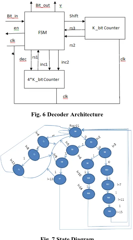
[image:5.595.58.277.176.569.2]Figure.6 shows the decompression architecture. This architecture consists of two counter (FSM), Bit swapping logic array and circuit under test. The FSM determines the binary value for the corresponding run length code. The bit in value is taken as input data from encoder and changed into FSM decode. The clock pulse is provided for each processing in the system. The rs1, rs2, and rs3 are the reset function. It states that whether the 4k counter is enabled or disabled.
Fig. 6 Decoder Architecture
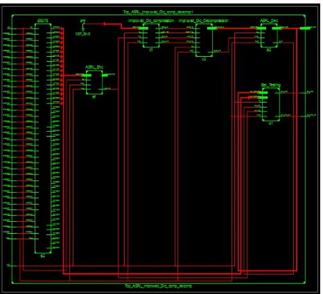
Fig. 7 State Diagram
The FSM model for the ASRL code is shown in figure.7.In this state diagram the state transition is taking place based on the run length value. For example, S0 is the
first state which is assigned with tail value for LSB as 01. This S0 is moved to two states S3 and S5. The length of this transition is measured based on the run length code. Binary values are taken for MSB (0 and 1). The length between S0 and S3 is 2 due to the value of 0 in MSB. 001 is the length (S0-S3) while checking the run length code it pointed the value as 2. Based on the MSB and LSB values the length of each transition is done.
V.RESULTS & DISCUSSION
To evaluate the proposed method, a series of experiment is performed for the S5378 and S9234 benchmark circuits. The proposed system output was analyzed against the existing system. The code is synthesized in Xilinx 14.2 SPARTAN-6 XC6SLX100-2FGG484 FPGA. The results are tabulated in Table 2.
Table. 2 Comparison of Compression methods Existing
ASRL[22]
Existing Improved
DBCT [25]
ASRL+ Improved
DBCT
S537 8
S923 4
S537 8
S923 4
S537 8
S923 4
Test Bits 48 48 48 48 48 48
Input Bits 18 18 16 16 18 18
Total Bits 864 864 768 768 864 864
Compressi on Ratio %
65.1 6
67.1 8
63.2 4
65.2 80.2 5
82.5
The total bits are calculated based on the equation. Total Bits (t0) = tb * i
Where, tb = Number of test Bits i = Number of Input Bits
Compression Ratio (CR) is calculated using equation 1.The analysis of existing ASRL technique and the proposed double compression technique using ASRL with improved Dictionary based compression is discussed in this section for the two sequential benchmark circuits S5378 and S9234. Table 3 gives the comparision of the above two compression methods.The graph is plotted to analyze the compression ratio between the proposed and existing method which is illustrated in figure 8.
Table. 3 Compression ratio (%) Comparision with other methods Bench Mark
Circuits ISCAS’89
CPRL [24]
OSCCPRL [31]
FR-PRL [27]
ASRL [22]
Improved DBCT [25]
ASRL+Improved DBCT [Proposed method]
S5378 61.08 71.15 61.04 65.16 63.24 80.25
S9234 62.95 75.93 59.02 67.18 65.2 82.5
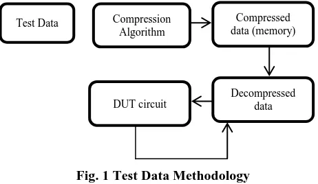
Fig. 8 Compression Ratio for Benchmark circuits The area, power and delay comparisons of the proposed technique for the two benchmark circuit’s s5378 and s 9234 are given in Table.4. The RTL Schematic of the proposed compression methods are shown in figure.9 and figure.10.
Table. 4 Area, Power and Delay Comparisons
Parameters
ASRL-Improved DBCT
ASRL-Improved DBCT
S5378 S9234
Slice Registers
422 397
LUT 690 736
Occupied Slices
315 306
MUX 164 160
IOB 54 32
Delay(ns) 5.515 7.686
Power(mW) 91 91
Among these two circuits, can see a variation in LUT and MUX based on the process and get different delay values. S5378 circuit provides a 5.515 ns delay whereas S9234 circuit provides 7.686 ns delay. These two consuming the same power for its process it about 91mW.
Fig. 9 S5378 RTL Schematic Diagram
Fig. 10 S9234 RTL Schematic Diagram
VI.
Conclusion
In VLSI, the chip size plays a vital role in designing the system. If the circuit size gets larger then it may affect the power of the circuit. In order to reduce the memory utilization, the code has to be compressed in an adequate manner. This can take place through the double compression technique. In the proposed system, the Improved DBCT approach and Alternating Statistical Run Length Scheme is used for enhancing the compression ratio. In the existing ASRL system, the compression ratio is about 65.19% and Improved DBCT is about 63.24%, whereas in the proposed system the compression ratio is about 80.25% for s5378.The compression ratio for s9234 is 82.25% in the proposed work which is 67.18% in ASRL and 65.2% in Improved DBCT. Thus our approach provides an advantage of having better compression ratio than the previous methods. In future this work can be enhanced by reducing the testing power using some power reduction techniques.
REFERENCES
1. L. Li, K. Chakrabarty and N. Touba, “Test data compression using dictionaries with selective entries and fixed-length indices,” ACM Transactions on Design and Automation in Electronic Systems, Vol. 8, no. 4, pp. 470–490, 2003.
2. RhenAnjeromeBedruz and Ana RizaF.Quiros, 2015, "Comparison of Huffman and Lempel-Ziv Algorithm for Audio, Image and Text Compression", IEEE - Philippine Section”, pp. 9-12.
3. AlirezaYazdanpanah and Mahmoud Reza Hashemi, 2011, “A simple lossless preprocessing algorithm for hardware implementation of Deflate data compression”published in Electrical Engineering (ICEE),
19th Iranian Conference.
4. P. Raja Gopal and S. Saravanan, 2015, “Low Power Estimation on Test Compression Technique for SoC based Design”, Indian Journal of Science and Technology,Vol. 8, no. 14
5. Komal Sharma and Kunal Gupta, 2017, “Lossless Data Compression Techniques and Their Performance”,International Conference on Computing, Communication and Automation (ICCCA2017)
6. Gonciari PT, Al-Hashimi BM, Nicolici N, 2003, “ Variable-length input Huffman coding for system-on-a-chip test”, IEEE Transactions on Computer Aided Design, Vol. 22, no. 6, pp. 783–796
7. SanjoyMitra and Debaprasad Das, 2018, “An experimental analysis of the effect of fault dropping on Huffman based test data compression techniques”, International Journal of Pure and Applied Mathematics, Vol. 119, no. 15, pp. 391-398.
0 20 40 60 80 100
S5378
[image:6.595.53.286.524.736.2]8. Yuan H, Mei J, Song H andGuo K, 2014, “Test data compression for system-on-a-chip using count compatible pattern run-length coding”,Journal on Electronic Testing, Vol. 30, no. 2, pp. 237–242
9. E. JebamalarLeavline, K. Thaneesh Kumar, C. Vimal Raj and B. Surya Raj, 2015, “Enhanced 2n PRL Code for Efficient Test Data Compression”, International Journal of Innovative Research in Computer Science & Technology (IJIRCST),Vol. 3, no. 5
10. MD. AjmalSadiq,T.NagaRaju and Kumar. Keshamoni,
2013,“Modeling And Simulation Of Test Data Compression Using Verilog”, International Journal Of Electronics And CommunicationENGINEERING &TECHNOLOGY (IJECET), Vol.4, no. 5, pp. 143-151
11. VijayakumarSuvvari and M.V.H. BhaskaraMurthy, 2013, “VLSI Implementation Of Huffman Decoder Using Binary Tree Algorithm”,
International Journal Of Electronics And Communication Engineering & Technology (IJECET), Vol. 4, no. 6, pp. 85-92
12. Shilpa.K.Meshram and Meghana.A. Hasamnis, 2011, “Huffman Encoding using VLSI”, International Journal of Electrical and Electronics Engineering (IJEEE), Vol. 1, no. 2, pp. 2231 – 5284 13. Seok-Won Seong and PrabhatMishra, 2008, “Bitmask-Based Code
Compression for Embedded Systems”, IEEE Transactions On Computer-Aided Design Of Integrated Circuits And Systems, Vol. 27, no. 4,
14. A. Wolfe and A. Chanin, 1992, “Executing compressed programs on an embedded RISC architecture”,In Proceedings of International Symposium, pp. 81–91.
15. H. Lekatsas and W. Wolf, 1999, “SAMC: A code compression algorithm for embedded processors”,IEEE Transactions on Computer Aided Design and Integration Circuits Systems, vol. 18, no. 12, pp. 1689–1701
16. H. Lekatsas, J. Henkel and V. Jakkula,2002, “Design of an one-cycle decompression hardware for performance increase in embedded systems”,In the Proceedings of Design and Automation Conference, pp. 34–39.
17. C. Lefurgy, P. Bird, I. Chen, and T. Mudge, 1997, “Improving code density using compression techniques”, In the Proceedings of International Symposium MICRO, pp. 194–203.
18. S. Liao, S. Devadas, and K. Keutzer, 1995, “Code density optimization for embedded DSP processors using data compression techniques”,In the Proceedings ofAdvanced Research in VLSI, pp. 393–399. 19. HemrajKumawaAndJitendraChaudhary, 2013, “Optimization Of Lz77
Data Compression Algorithm”, In International Journal Of Computer Engineering &Technology (IJCET),Vol. 4, no. 5, pp. 42-48
20. Rosinger P, Gonciari PT, Al-Hashimi BM and Nicolici N , 2001, “Simultaneous reduction in volume of test data and power dissipationfor systems-on-a-chip”, Electronic Letters, Vol. 37, no. 24, pp. 1434– 1436
21. Ruan X and Rajendra K, 2006,“An efficient data-independent technique for compressing test vectors in systems-on-a-chip”, Emerging VLSI Technologies and Architectures. In: IEEEComputer Society Annual Symposium
22. HaiyingYuan,Kun Guo1,Xun Sun2 and Zijian, 2016,“A Power Efficient Test Data Compression Method for SoC using Alternating Statistical Run-Length Coding”, Journal of Electronic Testing, Vol. 32, no. 1, pp 59–686
23. C. Kalamani and K. Paramasivam, 2015, “Test Data Compression Using a Hybrid of Bitmask Dictionary and 2nd Pattern Runlength
Coding Methods , International Journal of Computer, Electrical, Automation, Control and Information Engineering, Vol:9, No:3, pp. 831-836
24. Haiying Yuan, Jaiping Mei, Hongying Song, Kun Guo, 2014, “ Test
dataCompression for System-on-a-Chip using count compatible pattern Run-length coding”, Journal on Electron test, Vol. 30, pp.237-242.
25. MD. AjmalSadiq and T. Naga Raju, 2015, “Modeling and simulation of test data compression using VERILOG”, International Journal of Electronics and Communication Engineering & Technology (IJECET), Vol. 4, no. 5, pp. 143-151
26. Haiying Yuan, Kun Guo, Xun Sun and ZijianJu, 2016, “A Power Efficient Test Data Compression Method for SoCusing Alternating Statistical Run-Length Coding”, Journal of Electronic Testing, Vol. 32, pp. 59–68
27. Haiying Yuan, ZijianJu, Xun Sun, Kun Guo and Xiuyu Wang, 2016, “Test Data Compression for System-on-chip using Flexible Runs-aware PRL Coding”, Journal of electronic testing, Vol. 32, no. 5, pp. 639-647
28. AnjuAskona and J.P Anita, 2016, “ Multistage test data compression technique for VLSI techniques”, International Conference on Advanced Communication, Control and Computing Technologies, pp. 65-68
29. KanadBasu and PrabhatMisra, 2010, “Test data compression using efficient bitmask and Dictionary selection method”, IEEE transactions on Very large Scale Integration(VLSI), Vol. 18, no. 9, pp. 1277-1286 30. Lung-Jen Lee, Wang-Dauh Tseng, Rung-Bin Lin and Cheng-Ho
Chang, 2012, “2n Pattern Run-Length for test data compression”, IEEE transactions on Computer Aided Design and Systems, Vol.31, no. 4, pp. 644-648
31. Harpreetvohra and Amardeep Singh, 2016, “Optimal Selective Count Compatible Runlength Encoding for SoC Test Data Compression”, Journal for Electronic Testing, Vol. 32, no. 6, pp. 735-747
32. K. Radhika and D. MohanaGeetha, 2018, “Augmented Recurrence Hopping Based Run Length Coding for Test Data Compression Applications”, Wireless Pers Communications, Vol. 102, no. 4, pp. 3361-3374.
![Fig. 4 Encoding Format for Improved DBCT [25]](https://thumb-us.123doks.com/thumbv2/123dok_us/8180240.254740/4.595.43.290.284.402/fig-encoding-format-improved-dbct.webp)