International Journal of Innovative Technology and Exploring Engineering (IJITEE) ISSN: 2278-3075, Volume-8, Issue-11S, September 2019
Abstract: Face recognition system is widely used for human identification particularly for security functions. The project deals with the look and implementation of secure automatic door unlockby using Raspberry Pi. Web camera for capturing the images from the video frame is operated and controlled by raspberry pi using Open CVPython library to train and store human faces for recognition. In this project we are using Raspberry Pi as face recognition module to capture human images and it will compare with stored data base images. If it matches with authorized user then system allows to supply power to electromagnetic lock to create magnetic field for unlocking the door. The need for facial recognition system that is fast and accurate is continuously increasing which can detect intruders and restricts all unauthorized users from highly secured areas and aids in minimizing human error. Face recognition is one of the most Secured System than the biometric pattern recognition technique which is used in a large spectrum of applications.The time and accuracy factor is considered about the major problem which specifies the performance of automatic face recognition in real time environments. Various solutions have been proposed using multicore systems. By considering present challenge, this provides the complete architectural design and proposes an analysis for a real time face recognition.
Thus, the image extracted and allowed to match with the database pictures. If the images are matched, the door unlocks mechanically. the planning of the face recognition system exploitation Raspberry pi will create the smaller, lighter and with lower power consumption, therefore it's a lot of convenient than the PC-based face recognition system. Principle element analysis LBPH (Local Binary Pattern Histogram) algorithmic program is employed for the face recognition and detection method. Then acknowledgement are send through Zigbee module from transmitter to receiver. If image isn't detected in database then it'll ask for manual four digit pin for unlocking the door.The developed theme is affordable, fast, and extremely reliable and provides enough flexibility to suits any environment of various systems.
Problem Statement:In theworld of emerging technology, security became an essential component in day to day life. Information theft, lack of security and violation of privacy etc. are the essential components which are needed to be protected. Using smart secure systems for door lock and unlocking became popular nowadays. This is system is being adapted by many countries and first grade countries such as USA, Japan etc., already makes use of this system. This system provides either a facial recognition security feature or a keypad is provided to enter the passcode which unlocks the door. Although, it provides security to the doors, it also has somelimitations and drawbacks: Firstly, if the system mainly uses a facial recognition module, there might be a slight chance that sometimes the face may not be detected and hence the door cannot be unlocked. Secondly, if the system uses a
Revised Manuscript Received on September 22, 2019.
Vijayalakshmi.M, Assistant Professor, SRM Institute Of Science And Technology, [email protected]
Krishna Vamsi Thulluri, B.Tech CSE 4th Year, SRM Institute Of Science And Technology, [email protected]
Charan Sai Kanchana, B.Tech CSE 4th Year, SRM Institute Of Science And Technology, [email protected]
keypad to enter the passcode to unlock the door, there might be a chance that the key maybe be recorded or can be observed by others without users consent. Hence, a two-step verification is developed which makes use of facial recognition as first step and passcode as its following step. But the same issues pertain in the newly developed system. Thus, a new model which rectifies all the above issues is developed.
Keywords—Face recognition; Local Binary Histograms; keypad password; electromagnetic lock.
I. INTRODUCTION
Security deft have suggested various preferred approaches like biometric and password to enhance security. But the technology is developed and growing with usage of different equipment's. The trend’s moved from fingerprint to face recognition. So, we prefer face recognition system for unlocking the door. Facial recognition is widely used in various industries and corporate sectors. This door unlocking system mainly uses facial recognition. A latest camera is used to detect the images and the images are send to the database. If the image matches with the admins image then the door is unlocked and an acknowledgement is sent via Zigbee as “y” if it does not match the image an acknowledgement is send as “n”. A pass code column is shown which takes values from the keypad to unlock the door. In today’s world by using smart devices we makeour needs smart. By following trends and updates we have to consider and remove drawbacks in existing system and add more features and updates. Face detection system is more complex because of unstable characteristics. Example: let us consider glasses and beard will show some impact to detect the faces. So, by considering the different angles and multiple images of faces and it will influence on detection process. The study of Open-CV and its inbuilt library functions helps to generate a code will do correct and authentic facial recognition system with new and more efficient use of hardware. Human body will be identified as an input within environment by capturing live video from web camera and the process will be done on captured video frames. The images will run through raspberry pi3 and check with the stored data base in this case used a 16gb memory card. The compilation process will performed in VNC Viewer which helps to run Raspbian Os and the response will send to micro controller which is connected to Zigbee receiver and power is supplied to this micro controller by transformer and a keyboard is connected to this micro controller and display board is also connected to it. This will control motor driver to lock and unlock the door. To run this model there are different algorithms in that we took LBPH because it will provide more accuracy results when compare to other
algorithms. By this we can say that door locking and unlocking by detecting faces is a new
Face Recognition Door Unlock System
model which includes an alternate manual pass code unlocking system by using keypad which helps to gain access to that door in necessary situations.
II. RELATED WORK
This section provides various approaches towards door unlocking system. In previous works they deal with different algorithms technologies and equipment’s for unlocking door. In reference article 8 study by Somjit Nath, Paramita Banerjee proposed “Arduino Based Door Unlocking System with Real Time Control”. This approach implemented with RFID codes to scan for unlocking the door. So, when a person wants to enter the door, he needs to scan the card then he gains access to that door. If he misplaces that card he cannot access through that door and there is chance of insecurity that anyone can access to door with that misplaced card. which stands as a drawback to this system. In reference article 7 study by Charoen Vongchumyen, Pakorn Watanachaturaporn, pattaya proposed “Door locking system via web application”. In this approach a web application is designed to monitor the door so that user can easily access door by his mobile and he can also check the status whether it is locked or not. There is a drawback in this system: when someone hacked and got security code then hackers can easily access to that room. In reference article 2 study by Suchit Shavi proposed” Secured Room Access Module”. In this approach a keyboard-based door unlocking system is implemented with micro controller. So, the user needs to enter his password to unlock the door. In this approach is secured when compared to the previous models and well used in today’s world. Even though, this system is secured there might be a drawback: If someone observes your password, they can gain access to that door by using the same password you have entered. In reference article 1 study by Muhammad Kashif shaikh, Syed annas bin Mazhar proposed “Comparative Analysis for a Real Time Face Recognition System Using Raspberry Pi”. This approach did an analysis of various algorithms on face recognition system. This analysis took LBPH (Local Binary Pattern Histogram), Fisher Faces, Eigen Faces Algorithms for comparison and checked with different processors to know time complexity and accuracy of various algorithms. This approach is most secured and without matching face no one can access that door. Hence this survey work proves that face recognition system is best approach for using in present days. By referencing this approach we designed a new type of door locking and unlocking system.
III. SYSTEM ANALYSIS 3.1 Transmitter
In this, we've got a tendency to using Raspberry Pi for connecting with the camera module to capture photos continuously through the open CV platform. This open CV runs in VNC viewer that helps to run raspbian Os. At first, we've to attach raspberry pi with LAN port then our pi is going to be assigned to associate degree IP address. we've to configure the same IP address in VNC viewer to run raspbian Os through this python code can execute and pictures are
[image:2.595.312.540.94.210.2]going to be captured through the camera and compared with saved data images and send an acknowledgment signal to a different controller unit through Zigbee.
Fig. 1: Block diagram of Transmitter
3.2 Receiver
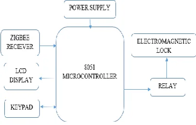
Receiver unit gets the acknowledgment signal from the Zigbee transmitter and works consistently according to the acknowledgement data. If the received signal is “Y” then power is directly equipped to the electromagnetic lock through the relay. If the signal is “N” then it'll arouse a keypad pass-code. we've to enter that code manually through four X 4 matrix keypad that is connected to the micro-controller with the input of +5V. The pass-code that entered is valid then power equipped to electromagnetic lock through the relay. If the entered pass-code isn't valid the door standing remains locked.
Fig. 2: Block diagram of Receiver
IV. EXISTING SYSTEM
The purpose of this present mechanism is for secure a sectionthat will be lockedthat might be opened only by providing a signature. The preset countersign is holding on in data. If someone needs to open the lock, they must enter the valid countersign, by utilizing the 4 by 4 matrix keypad. If the countersign matchesthe retention none, the micro-controlleroperates the relay switch and therefore the lock will be open. when the lock opened, the micro-controllerwill reset the relayto its previous state and, therefore, the lock closes mechanically. Ifthey entered an invalid password, the liquid crystal display will show to the user enter password. The most complete plan is to supply a lock which might be free by coming into a sound and a previously saved countersign that
[image:2.595.309.511.405.534.2]International Journal of Innovative Technology and Exploring Engineering (IJITEE) ISSN: 2278-3075, Volume-8, Issue-11S, September 2019
fundamental representation that will shows all the foremost blocks that helps to frame this module.
This includes the following:
1. Power supply 2. Micro-controller 3. keypad
[image:3.595.57.290.182.284.2]4. liquid crystal display 5.Electromagnetic Relays.
Fig.3: Block diagram of Existing system
The power obtained from the controller is applied directly to the microcontroller and requires +5V. The keyboard input key is input to the microcontroller. The display on the LCD is the same when scanning and characterizing the buttons. The keyboard is connected to port 1, and the alphanumeric screen is connected to port 2 of the microcontroller. During the reset, the first password will be deleted and the new password must be saved in its memory. Once the wrong password is entered, the relay controller will not send enough voltage to control the relay circuit and the door will remain closed. After entering the correct password, the relay controller sends enough voltage to the relay circuit to unlock the door. The +12V generated by the controller is applied to the relay circuit. In addition, often use EEPROM
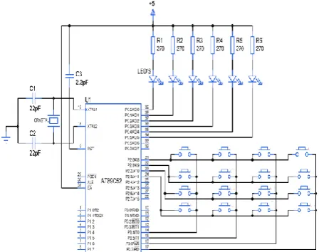
Fig. 4:Circuit diagram of Existing system
4.1 8051 MICROCONTROLLER
8051 MICROCONTROLLER is that the IC from C51 micro-controller family. The AT89S52 may be a high performance and low power consumption of CMOS and nonvolatile storage that is programmable and efface able scan solely memory (PEROM) having an 8-bit digital computer with 8Kb. The device is an Atmel factory mistreatment of
high-density non-volatile memory and is compatible with the usual trade of 80S51 and 80S52 instruction set and pin-out. Flash allows a system or non-volatile memory software engineer to reprogram the memory of the on-chip program. Combine a flexible 8-bit host with Flash on a single chip. The 8051 will be a powerful digital computer that provides a cost-effective and versatile solution for a wide range of small management applications.It is an 8-bit small.
PROPOSED SYSTEM
In proposed system presents regarding using of LBPH (Local Binary Pattern Histogram) algorithmic program. This algorithm can offer us a lot of correct results after we compare to different sorts of algorithms like Fisher Face, Eigen Faces Algorithms. This LBPH algorithm can take the number of pictures as you would like in several angles and check those all images at the time of face nonrecognition. In our case, we tend to are taking twenty pictures of someone with totally different angles and it'll be holding on in our database. For this algorithmic program, we tend to are using the VNC viewer to run raspbian Os for detection pictures from the info. At first, we've to save pictures by using data sets and then, we are going to train that faces to algorithmic program then it stores into the info. At first, it converts color pictures to grayscale images then it converts into constituents for detection this will divide the image into numerous items then it stores the values of every pixel. If pixels are less then it'll be described as zero and pixels that are high are one then it will be organized in 3 x 3 matrix format for recognizing the new pictures on screen compared to info stored images. Here are some totally different variations of faces that's capture and a flow diagram for LBPH algorithm controller which is three timers, Port one having four parallel ports. It is a 40-pin Dip package IC which is 128 bytes of RAM and 4KB of read only memory. It runs at a frequency of 11.0592 MHZ 4.4.
IV. DISADVANTAGES It Provides less security
Every time password entering required for unlocking
Micro controller cannot interface high power devices directly
V. PROPOSED SYSTEM
In proposed system presents regarding using of LBPH (Local Binary Pattern Histogram) algorithmic program. This algorithm can offer us a lot of correct results after we compare to different sorts of algorithms like Fisher Face, Eigen Faces Algorithms. This LBPH algorithm can take the number of pictures as you would like in several angles and check those all images at the time of face nonrecognition. In our case, we tend to are taking twenty pictures of someone with totally different angles and it'll be holding on in our database. For this algorithmic program, we tend to are using the VNC viewer to run raspbian Os for detection pictures from the info. At first, we've to save pictures by using data sets and then, we are going to
[image:3.595.49.277.484.661.2]info. At first, it converts color pictures to grayscale images then it converts into constituents for detection this will divide the image into numerous items then it stores the values of every pixel. If pixels are less then it'll be described as zero and pixels that are high are one then it will be organized in 3 x 3 matrix format for recognizing the new pictures on screen compared to info stored images. Here are some totally different variations of faces that's capture and a flow diagram for LBPH algorithm
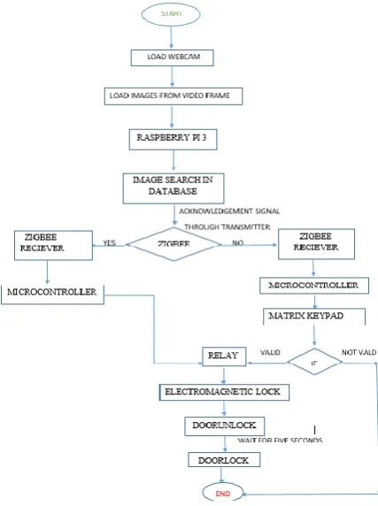
Fig 5 : LBPH algorithm flow diagram
This face detection method starts from the digital camera and image captured from the video frame are send to image acquisition. during this acquisition attractive work are going to be done there the image will be converted to greyscale and image improvement will be done at the moment it filters the image on balance this method face detection will be processed and data will share through Zigbee then it sends to the micro-controller. If image match then the door will unlock with electromagnetic lock
Fig.6 : Pre-Processing block of face detection
5.1 Proposed Methodology
[image:4.595.312.529.269.384.2]In this methodology provides secured verification door unlocking system that which will be unlocked by either automatic face recognition or by physical pass-code enter through matrix keypad. At first, the image are detected from the video frame of the digital camera and sends data to the raspberry pi. This pi searches captured image with database pictures. If the pictures are detected within the info then an acknowledgment signal “y “ are sent through Zigbee. Then data sends to micro-controller it provides power to relay to operate electromagnetic lock by supply power to form a magnetic field within the lock. If the acknowledgment signal is “ n” then micro-controller asks for four digit pass-code during this case. If the entered pass-code is valid it provides power to lock else door can stay within the locked state. when valid face or pass-code door are unlocked and it waits for five seconds and door will lock again
Fig 7 : Comparing three algorithms of face recognition rate
[image:4.595.308.522.412.698.2] [image:4.595.49.281.626.751.2]International Journal of Innovative Technology and Exploring Engineering (IJITEE) ISSN: 2278-3075, Volume-8, Issue-11S, September 2019
5.2 Advantages of Proposed system
1. High reliability.
2. It provides enough flexibility to suit the requirements. 3. More secure due to face detection.
4. Add more features according to user requirements 5. Easy to run and maintain
5.3 METHODOLOGY
Local binary pattern (LBP):It will be a simple and efficient function operator that marks image elements by thresholds close to each pixel and treats the result as a binary variable. It was initially developed as Local Binary pattern as known as (LBP) in 1994 and has since been found to be a robust function which is assigning a unknown image to one of set of known classes. it's been resolved on that once Local binary patterns are combined with histograms to adjusted gradients is called (HOG). Significantly improves detection performance in some data sets. Using LBP combined with a histogram, we can use a vector of direct knowledge to represent the image of the face. Since the LBP can be a visual descriptor, it can be used for facial recognition tasks, as shown in the following description.
1. Frame work:
Radio: Radius helps to make the native binary pattern circular and represents the radius around the center of the image. Usually it is built on one
Neighbor: Creates sample points for the circular native binary mode. The many sample points you hold, the higher the value of the machine.
Grid X: The number of cells in the horizontal direction. A large number of cells, the finer the mesh, the higher the part of the feature vector. Usually it is set to 8.
Grid Y: The number of cells in the vertical direction. A large number of cells, the finer the mesh, the higher the part of the feature vector. Usually it is set to 8.
2. Algorithm training:
First, we want to train the algorithm program. To do this, we want to use a set of data with the facial image of the person we want to identify. We want to create a correlation ID (which can also be a person's kind or name) for each image, so the algorithm can use this data to identify the relevant input image and provide output. Images of the same person must have the same identity. A training set has been created, let's take a look at the steps of the LBPH machine.
3. LBP operation:
[image:5.595.312.549.48.132.2]The first step of the LBPH machine is to make an associated intermediate image that describes the first image in a very superior way, highlighting the facial characteristics. To do this, the algorithmic program uses the idea of a window, it supports the radius of the parameters and the neighbors.
Fig 9: Pixels and binary conversion image
For example, we have a grayscale image that will get the image size of a 3x3 matrix pixel with an intensity (0-255). Then, due to the threshold, we prefer to use the center value of the pixels in the matrix. The pixel value will be used to represent the new value of the eight surrounding neighbors. For each center pixel value, we will create a substitute binary value. Compared to the threshold, we will assign one for the higher value and zero for the lower value. The matrix will now only contain binary values (ignoring the center value). We want to connect all the binary values of each position of the matrix clockwise and replace the threshold with a binary value (for example, 10001101). We then convert this binary value to a decimal value and set this decimal value to the center value of the matrix, which is actually the image element of the first image. At the top of this process (LBP program), we have a replacement image that replaces the larger features of the first image.
Fig 10 : converted pixels arranging according to
radius
4. Histograms extraction:
Using the image generated in the last step, we will use the parameters of Grid X and Grid Y to divide the image into multiple meshes.
1. Since we have a grayscale image, each bar chart (each grid) can only contain 256 positions (0~255), indicating the appearance of the intensity of each image element.
[image:5.595.315.550.347.465.2]Fig 11 : Image conversion and grid arrangement
In this step, the algorithm program has been trained. Each created bar chart is used to represent each image in the guided data set. Therefore, given an input image of relevance, we tend to perform the steps on the new image again and create a bar graph representing the image.
1. In order to find an image that matches the input image, we tend to simply compare the two bar graphs and get the image with the closest histogram.
2. We can use various methods to verify the histogram, and the grayscale filtered image becomes a column array.
3. The local binary pattern operator works in the 3X3 pixel window of an image ..., R = [a11 ... ..amn]
4.I (X, Y) and let's say that gp denotes the gray scale value of a sampling point with the coordinates Xp, Yp in a circular neighborhood uniformly spaced from p sampling points and radius r around points Xc, Yc.
LBPH (Xc, Xy) = Σ7 n = 0 s (en-ic) 2n Hi = Σx, and I {fl (x, y) = i}, i = 0, ..., n - 1, Ni = HiΣn - 1j = 0Hj. (two)
Therefore, the result of the algorithmic program is that the ID of the image with the bar graph of the nearest histogram. The algorithmic program must arrive together at the calculated distance, which could be used as a "confidence" measure.
5.4 CONCLUSION
1.LBPH is one of the simplest facial recognition algorithms.
2.Represents native options within the images.
3.It is feasible to encourage good results.
4.It is useful for monotonic grayscale transformations.
[image:6.595.300.554.96.219.2]5. It is provided by the Open CVlibrary.
Fig. 12: sample data set training images
5.5 DISCUSSIONS
In this result, we test in different types of systems to know the accuracy of this system according to the speed of the system's processing. This case that we capture and show different
machines that are used in the tests are listed below with their configurations.
Table 1: Machines used for time accuracy
Machine processor RAM Time
Required
Dell G3 Corei5(8th
generation)
8 GB 0.01399
Lenovo Corei7(4th
generation)
8 GB 0.01434
Dell inspironxps
Corei5(2nd generation)
6 GB 0.01514
Acer Aspire Corei3(4th generation)
4 GB 0.01567
This is the graphic representation of the performance and time needed to detect the human face by using the LBPH algorithm in the processors and systems listed above. The system with high configuration requires less time to recognize the face compared to other processors.
5. MODULES
1. Transmitter section:This consists of Raspberry pi,
[image:6.595.305.540.379.484.2]camera and Zigbee module. The camera captures images through Open CV and compared with stored authorized images. If it matches the control will send some unique character through Zigbee.
Fig. 13 : Transmitter Section
2. Receiver Section: This system consists of 8051 micro
[image:6.595.306.548.557.729.2]controller, keypad, LCD, Motor Driver, Zigbee and DC motor. The controller receives data of unique character and control movement of the motor. Here we are using L293D IC for controlling direction.
[image:6.595.60.288.649.700.2]International Journal of Innovative Technology and Exploring Engineering (IJITEE) ISSN: 2278-3075, Volume-8, Issue-11S, September 2019
VI. RESULT
All the modules present in this system are tested individually and then integrated into a single main module. Raspberry Pi was successfully programmed using python with open CV and Micro controller successfully programmed using Embedded C in the Keil vision software to achieve the unlocking system of the facial recognition door. The people who were authorized to access the door are placed in front of the camera and will capture the image of that person and compare it with the images in the database. If the images are recognized then the door will automatically unlock. When a person's images are not detected, they will ask for a manual pin to unlock the door. If that person entered a valid pin, the door will unlock. When a person enters the wrong password, the door does not open and he is denied access to the room. When image recognition is detected, the correct password is detected and the relay releases the door and allows the person to enter. This is tested by different combinations of face and password.
VII. RESULT & CONCLUSION
In this proposed door access system by using face recognition the images are stored in data base. This system is used door unlock access for Residential and Commercial Purposes. Here we have designed a highly secured door unlocking system by using Raspberry pi and micro controller under python and embedded platform.
Finally, this paper concludes for the advanced implementations achieved by integrating embedded system models against the convention.
We would like to thank S.Jagadeesan our guide who helped us in every step of the project
VIII. REFERENCES
1. (2017) “Comparative Analysis For a Real Time Face Recognition System Using Raspberry Pi” muhammad kashif shaikh , syed annas bin mazhar.
2. (2017) ”Secured Room Access Module” Suchit Shavi.
3. (2017) “Automatic Semantic Face Recognition”: Mark S. Nixon
University of Southampton Southampton, United Kingdom
4. (2017)“Real-Time Implementation of face recognition system” by Neel Ramakant Borkar and Sonia Kuwelkar, India
5. (2017) “IoT based Home security through Digital Image Process Algorithms” by A. Beatrice, Dr S. Britto Ramesh Kumar and J. Jerlin
Sharmila, India
6. (2017) “Secured Room Access Module” by Suchit and Shanvi, India
7. (2017)“Door locking system via web application” Charoen Vongchumyen, Watjanapong Kasemsiri, Kiatnarong Tongprasert,
Aranya Walairacht, Pattaya.
8. (2016) “Arduino Based Door Unlocking System with RealTime Control” Somjit Nath, Paramita Banerjee, Rathindra Nath, Biswas, Swarup
Kumar, Mitra.
9. (2014) K.Gopalakrishnan, V.Sathish Kumar “embedded image capturing system using raspberry pi system” international Journal.
10.(2014) “Development of Intelligent Automatic Door System” Daiki Nishida, Kumiko Tsuzura1, Shunsuke Kudoh1, Kazuo Takai,
Tatsuhiro Momodori.
11.(2012) “Face Recognition Based on Magnetic Door Lock System Using Microcontroller” Harnani Hassan, Raudah , Abu Bakar Ahmad
Faculty of Electrical Engineering.
12.(2005) “Real-time Embedded Face Recognition for Smart Home” by F. Zuo and P. H. N. de.