Rochester Institute of Technology
RIT Scholar Works
Theses
Thesis/Dissertation Collections
8-1-1993
Computer aided design and simulation of an
intergrated photonic delay line system for phased
array antenna and other microve signal processing
applications
Kevin Baldwin
Follow this and additional works at:
http://scholarworks.rit.edu/theses
This Thesis is brought to you for free and open access by the Thesis/Dissertation Collections at RIT Scholar Works. It has been accepted for inclusion in Theses by an authorized administrator of RIT Scholar Works. For more information, please [email protected].
Recommended Citation
Approved by:
Computer Aided Design and Simulation of
an Integrated Photonic Delay Line System
for Phased Array Antenna and Other
Microwave Signal Processing Applications
by
Kevin Baldwin
A Thesis Submitted
in
Partial Fulfillment
of the
Requirements for the Degree of
MASTER OF SCI ENCE
in
Electrical Engineering
Prof.
David ASumberg
(Thesis Advisor)
Prof.
1. Lorenzo
Prof.
FryTseng
Prof.
_
(Department Head)
DEPARTMENT OF ELECTRICAL ENGINEERING
COLLEGE OF ENGINEERING
ROCHESTER INSTITUTE OF TECHNOLOGY
ROCHESTER, NEW YORK
ABSTRACT
Overthe past few years, phasedarray antennas and variable RF/Microwave
delay
lines havebeen the subject of much research. This thesis presentsaphotonic solution to
the generation of multiple, compact
delay
lines. Variable time delays are generatedby
optically
tapping
points on an acousto-optic cellby
theuse of adeformablemirrordevice.Isolation of a particular time
delay
is accomplishedby
the conversion of a timedelay
point intoacorrespondingspatial
frequency by
the use of appropriate optics. The desired timedelay
is recoveredby heterodyning
a local oscillator with the desired spatialfrequency,
selectedby
a tiltable mirror device. Multipledelay
lines are producedby
theuse of a
binary
optic device. The design and simulation ofthe integrated optical systemwas carried out using a real ray
tracing
program writtenby
the author. Theoretical signalACKNOWLEDGMENTS
I would like to thank Dr.
Tseng
and Dr. DeLorenzo for sitting on my advisingcommittee and especially Dr.
Sumberg,
without whose patience and guidance this endeavor could nothave
come to realization. I would also like to thank Captain Ed Toughlian oftheRomeLaboratory
Photonics Center forextendingto methe opportunity to work on thistruly
novel project in times when original ideas are scarce, Dr.Henry
Zmuda for his advice, RIT's Department ofElectricalEngineering
for the marvelous educational opportunitygiven to me, Dr. A. Matthew forallowing meto work inone of thebestareas ontheRIT campus,Mom, Pop,
andtheGrandparents.Iwould also liketo thank some special people I have come to know overthe past
few years. To
fully
express the rolesthey
have played, I must draw an analogy to a sonnet:"The housewasold,withtangledwings
outthrownof which no one could evenhalf
keep
track. Andinasmallroom,somewhat neartheback,was an odd windowsealed with ancient stone.
There, inadreamplaguedchildhood,quitealoneIusedto go,
when nightreignedvague andblack,
partingthecobwebswitha curiouslackoffear andwithawondereachtimegrown.
One later
day
Ibroughtthemasonstheretofindwhat viewmydimforbears hadshunned,
butastheypiercedthestone
arush of airburst fromthealien voidthatyawnedbeyond.
They
fled,butIpeeredthrough
andfoundunrolled allthewild worlds of whichmy dreams hadtold." - HowardPhillips Lovecraft
I would like to thank Khaleda Najeem for revealing to me corridors yet to be
explored, Evelyn
Monsay
forhelping
remove the rubble from windows re-sealedby
others,Lee Minich who stoodby
myside atthewindowand offeredhiscouncil, and, mostimportantly,
Mr. Eric Rogala who has also forsaken the masons and dared to strideTable
ofContents
ABSTRACT ii
ACKNOWLEDGMENTS iii
Table ofContents iv
ListofTables ix
ListofFigures x
List ofAcronyms xv
Table ofSymbols xvi
I. Introduction 1
n. Phase
Array
Antenna Fundamentals 3Phased
Array
Antenna Operation 3DerivationofRequired Time
Delay
forAchieving
Steering
Angle 5Phase
Shifting
versusTrue TimeDelay
BeamSteering
8IE. Special Components Used intheIntegrated System Design 1 1
OperationoftheAcousto-OpticCell in
Bragg
Mode 1 1DerivationoftheExpectedAcoutso-Optic Cell Output: Amplitude
Modulation 12
Significanceofthe
Bragg
Angle 18DerivationoftheExpected Acoutso-Optic Cell Output:
Frequency
Modulation 18
DependenceofOutput Angle onAcoustic
Frequency
21Operationofthe
Binary
Optic Device 22IV. SinglePhotonic
Delay
Line Concept 24Generationof aTrue Time
Delay (TTD)
24General OpticalSystem for
Tapping
thePhotonicDelay
Line 26V. DesignoftheIntegrated Photonic
Delay
Line System 29The Significanceof
Ray
FansandDelay
Lines for System Design 29Underlying
Values Used forDesigning
30SimTI: ComputerSimulation andDesign Tool 31
Integrated System Overview 31
General DesignoftheIntegrated System 33
A Closer LookattheIntegrated System Front End Design 36
ACloser LookattheLocal Oscillator PortionoftheSystem Front
End 43
ACloser LookattheMultiple
Delay
Line Generation 54A CloserLookattheThird PortionoftheSystem: Collimationof
theIndividual
Delay
Lines 57ACloser LookattheFourth Sectionofthe System: Extractionof
theProper TTDandConfigurationforDetectionofthe Heterodyne
Signal 63
Specificationof
Coupling
Lens for DetectionAssembly
71VI. Real
Ray
Tracing
withTechniques for Computer Realization 80General
Ray Tracing
Technique 80Background 81
Basic
Philosophy
behind "UserFriendly"Optical System Design 81
Optical Componentstobe Considered 81
Useof aGlobal Coordinate System 82
General
Terminology
82RepresentationofOptical Surfaces 83
Describing
Planar Surfaces 84Describing
Spherical Surfaces 84ApplicationofSnell'sLaw 85
Atan
Arbitrary
Planar Surface 85Atan
Arbitrary
SphericalSurface 86AlignmentofOpticalComponents AbouttheOptical Axis 87
A Common Mathematical Operation 87
DecompositionofOptical Componentsinto Respective Surfaces 88
SpacerDecomposition 88
Wedge Decomposition 89
Lens Decomposition 91
Ray
Tracing
ThroughtheBragg
Cell 94Ray Tracing
ThroughtheBinary
Optic Device 96VU. SimH: An Overview 97
Introduction 97
Specifying
Components (UnitsofMeasurement)
97ParametersofOpticalComponentsUsed
By
Simll 97Block Parameters 98
Wedge Parameters 98
Lens Parameters 98
Acousto-OpticCell 100
GeneralProgramUsage 101
Entry
andManipulationofData 101Back-Tracking
To Abort UndesiredOperations 102Examining
anOptical System 102General
Terminology
104Optical System
Entry
andManipulation:The File Pulldown 105DescriptionsofthePulldown Functions 106
Ray Tracing
ThroughtheSystem: TheTracing
Pulldown 109DescriptionsofthePulldown Functions 110
Viewing
Generated Data: The Output Pulldown 115DescriptionsofthePulldown Functions 115
Viewing
theOptical System: The Graphics Pulldown 118Descriptionsofthe Pulldown Functions 118
AnImportant Note About
Using
theGraphics Screenfor Analysis 123EvaluationoftheIntegrated System: The Simulation Pulldown 125
Descriptions ofthePulldown Functions 126
MethodofOptimization 130
VIII. CalculationofSignaltoNoise Ratio 132
The Form ofOptics Related SignaltoNoise Ratios 132
Signal Power 132
The Classical Noise Sources 133
AdditionalConsiderations in SNR: EffectsofNon-Ideal Detector Size 138
DeterminationoftheSignal andLocal Oscillator Electric Fields 139
Determination of
Intensity
PatternatDetector Plane 142Quantification oftheEffectofDetectorSizeonSNR 149
Bibliography
154Works Cited 154
Additional References 155
Appendix A 156
Simll Source Code 156
AppendixB 157
Analysisofthe
Binary
Optic 157AppendixC 161
DerivationofTrigonometric
Identity
161Appendix D 162
List
ofTables
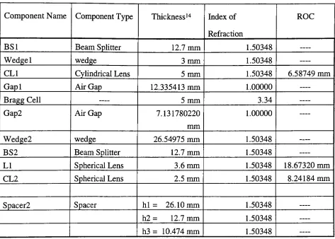
Table 1. SpecificationofFrontEnd
Components
53Table2. Specificationof
Delay
Line CollimationComponents 56Table 3.SpecificationofIndividual
Delay
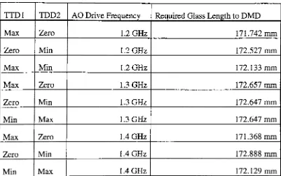
LineCollimation Components 62Table 4. Various Lengths ofGlassUsedin
Specifying
DMD Distance 67Table 5. InputGaussian Beam Characteristics 73
List
ofFigures
Figure 1. BlockDiagramofaPhased
Array
AntennaSystem 3Figure 2.GenerationofPlanar Wavefront fromMultiple Point Sources 4
Figure 3. Phased
Array
Antenna Output Field 5Figure 4. DerivationofRequired ProgressivePhase
Delay
for BeamSteering
6Figure 5. AntennaOutput for
Steering
Angleof 15o 7Figure6.Antenna Outputfor
Steering
Angleof45o 8Figure 7. Squint
Pointing
Error in Antenna Output 9Figure 8. An Acoutic Wave
Propagating
intheTransducerof anAO Cell 11 Figure 9. ReflectionsofaBeamofLightoffof aStructurePossessing
aPeriodicIndexofRefraction 13
Figure 10. AngleDefmationsUsed in Fresnel Coeffecient Calculations 14
Figure 11. Typical Heterodyne Detection Scheme 21
Figure 12.
Intensity
DistrubutionoftheOutputoftheBinary
Optic foraPlaneWave Input: Mesh Plot 22
Figure 13.
Intensity
DistrubutionoftheOutputoftheBinary
Optic foraPlaneWave Input: Contour Plot 23
Figure 14.
Tapping
aSpecific TimeDelay
ontheBragg
Cell 24Figure 15. Architureof aSingle Photonic
Delay,
asProposedby
ZmudaandToughlian 26
Figure 16.
Geometry
fortheDerivationofRequired Mirror Tilt Angle in Terms oftheDesired TTD 27
Figure 17. The Integrated System:
Ray
Fan Analysis 33Figure 19. SystemFrontEnd
Terminology
37Figure 20.
Focusing
LasertoActive AreaofBragg
Cell 38Figure 21.
Maintaining
ProperBragg
Angle Incidence 39Figure22.
Maintaining
ProperBragg
AngleIncidence:Required Wedge Angle 39Figure23.Collimationof
Ray
FansExiting
SystemFront End 42Figure 24. The LocalOscillator PortionoftheSystem Front End 44
Figure 25. ASimple Telescope Configuration 45
Figure 26. TheDesignofSpacerl fortheSystem Fron End 47
Figure27. Possible LocalOscillatorBranch Configurations 48
Figure 28. Final Spacerl Dimensions 49
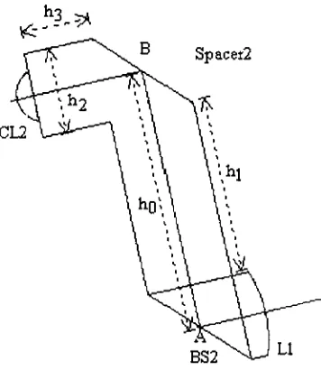
Figure29. DesignofSpacer2oftheSystem Front End 49
Figure 30. System for GenerationofMultiple
Delay
Lines 54Figure 31. Collimationof anIndividual
Delay
Line 57Figure 31. Collimation ofanIndividual
Delay
Line 58Figure32. DeterminationofDMD Location for
Ray
FanConvergence 64Figure 33. SeparationofSignalandLocal Oscillator Beams 69
Figure 34. Iterative
Ray
Tracing
Process 80Figure 35.Global Coordinate System 82
Figure 36. DefinitionofComponent Descriptors 83
Figure 37. RealizationofSnell's Law in Coordinate System 85
Figure 38. DecompositionofaSpacerinto Surfaces 88
Figure 39. DecompositionofaWedgeinto Surfaces 90
Figure 40.Decompositionof aPlanoconvex lens intoSurfaces 1 91
Figure 41.Decompositionof aPlanoconvexlens into Surfaces II 92
Figure43.Decompositionof aPlanoconvex lens into Surfaces II 94
Figure45.
Specifying
Lens OrientationtoSimll 100Figure46.SimHFront End 101
Figure 47. A TypicalSelection Boxin SimH 101
Figure 48. A TypicalPrompt BoxinSimH 102
Figure 49. ASample System DescriptionWindow 103
Figure 50. TheSample System
Description,
as seenusingtheGraphicsOption 104Figure51. Introductionto
Terminology
usedinDescribing
theIntegratedSystem 105Figure 52. The File Pulldown 105
Figure 53. Macro Alter Window 106
Figure 54. Add Component Window 106
Figure 55. Enter Parameters Box for
Adding
aComponent 107Figure56. Processof
Inserting
aComponentintoanExisting
Optical System 108Figure 57.
Altering
theParametersof anExisting
Optical Component 109Figure58.
Ray Tracing
Pulldown 1 10Figure 59.
Ray Tracing
Parameters 1 10Figure 60. Sign Convention Used in Simll for
Describing
InputRay
Trajectories IllFigure 61. Sign Convention Used
by
SimllinDescribing Binary
Optic DiffractedOrders Ill
Figure62. Resultof
Using
theRay
Trace Option 112Figure 63. Beam Trace Window 1 12
Figure 64. Result of
Using
theBeam Trace Option 113Figure 65. Multi-Beam Trace Prompt Box 113
Figure 66.
Ray Tracing
OptionsundertheMulti-Beam TraceOption 114Figure 68. SimHDefaultWindow 114
Figure 69. Output Pulldown 1 15
Figure70. Sample
Ray
Trace Information Window 1 16Figure 71. A Detailed
Description
Windowof aSystem Component 117Figure 72. Windows
Showing Refracting
Surface Parameters 117Figure 73. The OutputOptions Box 1 18
Figure 74. GraphicsPulldown 118
Figure 75. A Sample OpticalSystemasSeen FromtheTextScreen 119
Figure 76. A Sample Optical Systemas SeenFromtheGraphics Screen 1 19
Figure 77. TheGraphicsOptionsWindow 120
Figure 78. An Exampleof
Showing
theIntercept NumbersontheGraphics Screen 120Figure 79. An Exampleof
Showing
Surface PointsontheGraphics Screen 121Figure 80. An Exampleof
Plotting
DataUsing
Simll 123Figure 81. An Optical System Under Normal View 124
Figure 82. An Optical System Under Increased Magnification 124
Figure 83. An Optical System Under Further Magnification 125
Figure84. An Optical System Under Still Further Magnification 125
Figure85. The Simulation Pulldown 126
Figure 86. Information Generated
By
AO Collimation Check Under SimulationPulldown 126
Figure 87. The Physical
Meaning
oftheLens Displacement OptionundertheSimulation Pulldown 127
Figure 88. Lens
Steering
Parameter Window 128Figure 89. Optimize Thickness Window Available intheSimulation Pulldown 130
Figure 91. Originofthe
Cylinderical Signal
Beam 140Figure 92.ACondensed
Ray
Diagram
oftheIntegrated System 149List
ofAcronyms
DMD DeformableMirror Device
TTD TrueTime
Delay
AO Acousto-Optic
Table
ofSymbols
Squarerootof- 1
Section II.
0
X
As
k
4>(0)
C0(
v
d
td
'oBeamsteeringangle
Wavelengthofantenna
driving
signalDifference inperpendiculardistances
Wavenumber of antenna
driving
signalProgressivephase
delay
Angular
frequency
ofantennadriving
signalSpeedat which emittedsignalpropagatesinair
Antennaelementspacing
Time
delay
Section UI.
q
corf, ^
So
vs
n
An0
O
e
Acousticwave number
Acousticsignal angular
frequency
Amplitudeof acoustic wave
Speedof sound intransducer
Averageindexof refraction oftransducer
Maximumdeviationoftransducerindex fromaveragevalue, n
Phase shift ofacousticwave
Angulardifference between incidentopticalray andacoustic
Ar Incrementalchangeinreflectance
Ax Incrementalchangeinposition onthe transducer
dr/dx Change inreflectanceperchangeinposition
k Wavenumberofoptical wave
dn/dx Change in indexofrefractionper changeinposition
dr/dn Changeinreflectanceperchangein indexof refraction
01 Angle between incidentrayandsurface normal
02
Angle betweentransmittedrayand surface normal3
Anglebetweenreflectedrayand surface normaln\ Indexof refraction seen
by
incident rayn2 Index of refraction seen
by
transmittedrayL Optical beamwidth projectedontransducer
A Wavelengthofacousticwave
0B
Brag
angle^signal
Frequency
oftheacousticsignalnBragg
Indexof refraction ofBragg
cellr Reflectance
c0'
^optical
Angularfrequency
of optical wavet Time
Ejn
Electricfieldamplitudeincidentonthe transducerEout
Electricfieldamplitude reflectedby
acoustic wavefronts4*5
(t)
Signalwaveusedinheterodyning
^LOW
Local oscillatorwave usedinheterodyning
As
Amplitude ofsignal wavetoet
*s
A0
^signal
Intensity
seenby
thedetectorPhaseshift of signalbeamwithrespectto thereferencebeam
Change in
Bragg
angleDifferencein RFsignalinthe
Bragg
cellfromcentraldriving
frequency
Section IV.
xo
t
em
F
q
Distancefromx=0point
alongthecenter ofthe transducer
Truetime
delay
Tiltangle of mirror
Focallength
Anglebetween desired spatial
frequency
and optical axisSectionV.
d
Fl
F2
F3
Beamdiameter
Focal lengthofLI
Focal lengthofL2
Focal lengthofL3
nglass>nBK7 Indexof refraction oftheglass usedinthe systemconstruction
Indexof refraction of air
Eedgeangle ofWedge 1 andWedge2
Minimumfocal lengthneededfor CL1
Focal lengthofCL1
Radiusof curvature
Thickness of
Gap
1 noiair0w
1min
fCLl
ROC
A0 One halftheangular spread ofaray fan
fLl
FocallengthofL1Dm
Diameterofbeam enteringtelescope^out
Diameterofbeamleaving
telescopeFl,F2 Focal lengthoflenses usedintelescope
d Lengthof glassbetweenCL2andLI
0OA
Angle betweenoptical axisbeforeand afterthesystemfrontend0}Vf
Angle between reflectingsurfaceofSpacerl andinputoptical axishx
A dimensionofSpacer2dgst
Estimated lengthofglassbetween CL2andL 1dact
Actual length of glassbetween CL2andLI A% Percentdifferencebfl Back focal length
yjast Heightof ap rayasitexitstheopticalsystem
6'last
Angle exiting p raymakes withtheopticalaxistBL
1est Estimated lengthofBL 1ROCspiest
Estimatedradiusof curvature ofSP1(L3)
fSPlest
Estimated focal lengthofSP1*BL
1 Actual lengthofBL 1Cside
Lengthof a sideofa pentaprismmx Slopeof aline
bx
y interceptofalinexo>Yo Apoint on aline
tBL2
Lengthof glassbetween SP1 andBS3A, B, C,
DZo
w,
z
0,
oo
Elements
oftheparaxialraymatrixRayleighrange of aGaussianbeam
Waistradius ofGaussian beam
Distance from beamwaisttocurrent position onbeamaxis Beam divergence angle
SectionVI.
xo>yo
R
'm
Or
0,
3V
m
0q
9i
A
X
Centerof curvature
Radius of curvature
Angle betweenrefractingplaner surface and xaxis
Angle between incidentray and x axis
Angle between incident ray and surface normal
Angle between exiting rayand x axis
Angle betweensurface normal andexiting ray
Angle betweensurface normal and x axis
Diffractiveordernumber
Angle betweenmthdiffractiveorder and optical axis
Angle between incident rayand opticalaxis
Periodofdiffraction grating
Angulardifference betweenadjacentdiffractiveorders
Section VII.
R Radius of curvature
n Indexof refraction
Section VIII.
/
Mean-squared
value of a randomvariableerf
Varianceof random variabletfshot
Noisepowerassociatedwith shot noiseai2<tor*
Noisepowerassociatedwithdarkcurrenta]
johmon Noisepower associatedwiththermalnoise<isig> Averagevalueof signalcurrent
9-t
Responsivity
ofadetectorq Fundamentalcharge of anelectron
/zco
Energy
storedinaphoton<PS> Averageopticalpowerinsignalbeam
<Pl> Average optical powerinreferencebeam
B Bandwidthofthedetectionsystem
R,
Rl
Totalresistancein detectioncircuitk Boltzman'sconstant
T Ambienttemperature(in
Kelvin)
ir\
DarkcurrentTs
fractionoftotalinputpower placedinsignalbeamT^o
Transmission efficiencyofBragg
cellTp
Transmission efficiencyofPolarizerTcube
Transmission efficiencyofbeamsplitterGpjn
GainofphotodetectorGamp
GainofdetectioncircuitBO
Splitting
ratioofBinary
OpticAs
Amplitude of signalbeamfo
Opticalcarrierfrequency
fs
RFsignalfrequency
X
Opticalwavelengthx, y,z Cartesiancoordinates
0 Mirrortiltangle
V
Velocity
of soundinthetransducerT Desiredtruetime
delay
F Effectivefocal lengthofthesystem
fx
Spatialfrequency
O,
f
, ())"Relativephaseshifts
Es
Electricfieldof signalbeamELO
Electric fieldofLocal Oscillator beamTl Intrinsic impedanceof air
I
Intensity
patternPLO Power
density
oflocal oscillatorbeamPs Power
density
of signalbeamPDC
DCcomponentoftimevaryingintensity
patternpSIG
ACcomponentoftimevaryingintensity
patternL Introduction
Phasedarrayshave beenthesubjectofintensiveresearchforseveral
decades,
withtheprimary focus oftheseefforts centeredonmicrowave components and system. More
recently,
however,
optically basedsystems have beenproposed as possible alternatives tosome ofthemoreconventionalelements.
Many
true timedelay (TTD)
beam steering systems have beenproposed, such asthe schemes presented
by
Toughlian & Zmuda1'2 andSumberg
& Toughlian3>4- Thesystem addressed
by
this thesis combines an acousto-optic deflector with a segmentedmirrordevicetoobtaintime
delay by
thefollowing
process.AnopticalbeamofdiameterDpasses throughan acousto-optic deflectortowhich
an RF
frequency
is applied. The laserbeam that passes through the acousto-optic cellcarries afinite time slice ofthe RF signal.
By
means of a shift inthe opticalfrequency,
that time slice is impressed upon across section ofthe laser beam. The signal carrying
optical beam is then transmitted through an integrated (all glass) optical system to a
photodetector, where it combines with a second beam at the unshifted laser frequency.
The two beams produce a heterodyne signal.
Using
a mirror to steer one of the laserbeams,
it ispossibleto select variousdelay
points oftheoriginaltime slice and reproducethe instantaneous RFsignal occurring atthat point. Time delays up to
D/vs
are possible,wherevs isthevelocityof soundpropagating intheacousto-optic cell.
1H.ZumdaandE.Toughlian,"Variable PhotonicDelayLinefor Phased
ArrayAntennasand
RF/Microwave SignalProcessing",Final TechnicalReport,(RomeLaboratory,Griffiss Air ForceBase,
NewYork,June 1991)
2H.ZmudaandE.Toughlian,"Adaptive Microwave Signal Processing: A PhotonicSolution,"
Microwave
Journal,Vol. 35,No.2Feb 1992,pp 58-68
3D.Sumberg,"An Integrated PhotonicDelayLineforPhased
Array
AntennaApplications",Final TechnicalReport,(RomeLaboratory,Griffiss Air ForceBase,NewYork,May
1993)4D.Sumberg,"An Electro-optic Based VariablePhotonic
Delay
Linefor PhasedArrayAntennaThe potential advantages of the segmented mirror photonic
delay
line overexisting architectures lie in it's ability to provide extremely rapid reconfiguration ofthe
antenna pattern and an
infinitely
variable time delay. An important advantage lies insteering the beam using a TTD technique as opposed to employing a phase shifting
technique. In some existing antenna systems, optical
heterodyning
schemes have beenemployed to provide an RF phase shift that
is,
unfortunately, independent of the RFfrequency. Such a system suffers from a phenomena know as squint, which results in
different
frequency
components of the RF carrier pointing in different directions.By
utilizing aTTD beamsteering technique,theeffects ofsquint areeliminated5
.
This thesis addresses the concept and design of a integrated photonic
delay
linesystem, concentrating on the role of a personal computer in
determining
systemspecifications andperformanceevaluation. The integratedsystemis capable ofproviding
25 separate
delay
lines (although only 20 lines will utilized in the actual system) with ahigh packing density.
The availability oftrue time
delay
lines for RF signals mayalso be utilized intherealization of microwave signal processing architectures.
By
using the variable photonicdelay
lines in conjunction with a photonic amplitude weightingdevice,
a microwavetransversal filtercan be realized. Such an amplitude weighting effect can be included in
theoptical system
by
theuse ofliquidcrystal lightvalues.5H.ZumdaandE.Toughlian,"VariablePhotonicDelayLine for PhasedArray Antennasand
RF/MicrowaveSignalProcessing",Final Technical Report,(RomeLaboratory,Griffiss AirForceBase,
II. Phase
Array Antenna
Fundamentals
Phased
Array
Antenna Operation
A phased-array antennais an antenna system which steers the outputbeamofthe
antenna
by
adaptivilycontrolling
the time ittakes fora common signal emitted from thesource to reach a particular radiative element. A simplified block diagram of a
one-dimensionalantennaarrayisshownbelow:
Phase Fronts
Delay: 8
(
nj ,0)Delay:
8(
1*2,8)Common
Source
/113
Delay: 6
(
n3
,0)Delay: 6
(
n4,0)Delay:
6(
n5,8)Figure 1. Ablock diagramof a phasedarrayantenna system. Theoutputdirectionofthebeam,specified
by
theangle6with respectto thearraynormal,iscontrolledbyvaryingthe timerequiredfora signal emittedfroma common sourcetoreach a particularelementintheantenna. Thus,theamount oftimedelayneededat a particular elementisafunctionofboththespatiallocationof a particular element andthe desired steeringangle.
Theamountoftime
delay
depends onthe desiredsignaldirection,
specifiedby
theangle 0 in Figure
1,
and the spatial location of the radiative element, designatedby
n[.Thus,
in order to achieve a desired steeringdirection,
the signal must be delayed anThe mechanism
by
whichthe beam is steered canbe seenby
firstconsidering theoutputfield resulting fromthe emissionsof an
arrayofsynchronized pointsources. Each point source represents anidealized
radiating
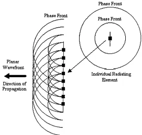
elementintheantennaarray.Phase Front
Phase Front
Planar
Wavefiront
Directionof Propagation
Individual
Radiating
Element
Figure 2. The resultingoutputfield fromanarrayof synchronized point sources. Sphericalwavefronts of equal phase are shownemergingfromeach point sourceinthearray. Itisevidentthat thesuperposition of thesphericalwavefrontsfromeach source contributeto thegeneration of a planar wavefrontpropagating
normalto thearray.
By
considering the linear array ofradiating antenna elements as an array of pointsources, the output field of the antenna array may be explored. As in Figure
2,
theresulting output field from the antenna generated
by
a linear array of synchronized oscillators will appeartobea planerwaveinthe farfield.This statement has been supported using aMathCad simulation to determine the
[image:27.557.136.425.154.429.2]by
summing
thesphericalfields generatedby
1 1 point sources, symmetrically distributedaboutthe 0 point ofthe x axis and with a separation distance between adjacent elements
of one half a wavelength. The figure below represents a contour plot of the resulting
outputfield.
300-+00
300
200-
100-M
Figure3. Contourplot ofthefieldresultingfromthesuperposition of1 1pointsources,locatedalongthe loweraxisoftheplotand centered aboutthe"zero"point. Theseparationusedbetweenadjacent elements
was one-halfthewavelength ofthecarrier wave. Notethat theresultingfieldappearstobequiteplanar, propagatingnormalarrayorientation.
From MathCad result shown in Figure
3,
it is apparent that the resulting outputfield distribution displays planer wavefronts characteristics in the "forward looking"
region,
directly
in frontofthearray.Derivation
ofRequired Time
Delay
for
Achieving Steering
Angle
As has been already stated, inordertosteerthe resulting beamatime
delay
inthesignal between adjacent elements must be introduced.
Since,
in this example, the signalberealized as a phase delay. Sincetotalphase
delay
isbeing
considereditcan bedirectly
usedinthequantificationof atime delay.
Theexpressionfortherequiredtotalphase
delay
interms ofthesteer anglecan bederived
by
considering Figure4:DirectionofPropagation
PlanarWavefiront
Wave Fronts contributing toPlanar Wavefiront
Figure 4. The geometryofthesituation
leading
to thederivationoftheamount of required phasedelay
betweenadjacent antennaelementsinordertoachievedesired steeringangle oftheantenna outputbeam.
Inthefigure,Asrepresentsthedifferenceinperpendiculardistances fromthewavefronttoadjacent point
sources and0issteeringangle ofthebeamwith respectto thearraynormal.
By
taking
a"snapshot"
in time of the wavefronts that contribute to a planar
wavefront, an expression canbe derived for the progressive phase
delay
in terms ofthesteeringangle. FromFigure 4:
sin0=
As As
Element
Spacing
X
2As=
A,sin0
(1)
Theprogressive phase
delay, O(0),
willbegivenas:,/nN , . 2%
XsinQ
. .(Q)
=kAs=- =7usin0
X
2(3)
wherekisthewavenumber, -y-.
Fromthis derivation it canbe seenthat inorderto steerthe beamat angle 0 with
respect to the array normal, the signal radiated
by
a particular element shouldpossess aphase
delay
of +/-O(0) comparedto the elements adjacent to it. The +/- factorreflectsthe not
knowing
if the adjacent element is on the "right" or "left" of the element inquestion. Inordertoillustratethe point,severalMathCad beam steering simulationshave
been carried out forvarious steer angles. In allcases, the antennais alinear array of 1 1
elementsarranged alongthexaxis, centeredabouttheorigin.
PhaseFronts ofOutput Field
500-
400-
300-
200-
100-n 1 1 r
100 200 300 400 500
M x
Figure 5. Acontour plot oftheoutputfield distribution fora steer angle of15with respecttothenormal
Phase FrontsofOutput Field
mkp 3y-'X'
^
40CT300"
Pi
P
20CT
P)P
1 '
100-&'!' 0-]
()
1 100
1 200
1 300
1
400 50
M x
Figure 6. Acontour plot oftheoutputfield distributionforasteer angle of45with respecttothenormal
to thelinearantenna array.
Noting
thattime andphasearelinearly
relatedata signalfrequency,
therequiredtime
delay,
tj,maybe expressedintermsofthephasedelay:_
<E>(0)
_7tA,osin0
_
X,osin0
(4)
coo
27T.V 2vThus,
the proper directional orientation of the output beam of a phased arrayantenna maybe achieved
by
generating the proper time delays for each element, baseduponthedesired steeringangle.
Phase
Shifting
versusTrue Time
Delay
Beam
Steering
As stated in the
Introduction,
some phased array antenna schemes make use of afixed phase
delay
system to control the direction of the output beam.However,
forbroadband signals such adirectional controller will result in the pointingerror knownas
squint. Squint results from different
frequency
components of the transmitted signalgeneralizing
the derivation of the beam steering angle,0,
presented earlier to multiplewavelengths.
Recalling
fromequation 1 that:A?
sin0=
(5)
Element
Spacing
Forthe transmission ofabroadbandsignal, it is no longerpossible to specify the
spacingofthe radiatingelementsinterms ofthetransmissionwavelength, as was done in
theearlierderivation.
Therefore,
letthespacingbetweenadjacentelementsbe fixedatavalue ofd. Thephase
delay
requiredtosteerafrequency
component oftheoutputbeamwillbegivenby:
<p= dsind
(6)
X
For a fixed phase system, O will remain a constant value for all frequencies
(wavelengths). Since all valuesareconstrained in equation exceptforthe beam pointing
angle, the beam pointing angle will become a function of wavelength, resulting in the
specification of adifferent beam direction for each
frequency
in thedriving
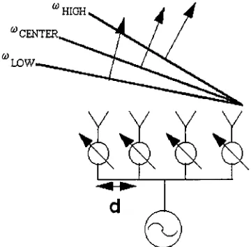
signal. Thisphenomenais known as squint. Thissituationisshownin Figure 7.
[image:32.557.187.367.446.623.2]"high
Figure 7. Theeffectofusinga phaseshiftingschemetogeneratetheoutputfieldof a phasedarrayantenna. Differentfrequencycomponentswill resultin different beam steeringangles. This pointingerroristermed
On theother
hand,
itcan be seenthatby
using aTTD scheme to steerthe outputbeam
direction,
that theeffects of squint canbeeliminated. Thiscan beseenby deriving
therequiredtime
delay
fora givensteeringanglefromequation6:$ 2ic . . A rf . n
td
= = -dsm0= sm0(7)
co A v
where dis the separation distance between elements inthe array and vis the velocity of
theoutputbeamradiation. Fromthisrelationship it is clearthatthe steeringangle isnow
independent of the signal frequency. Thus the effects of squint are removed from the
III. Special
Components
Used in
the
Integrated System
Design
Operation
ofthe
Acousto-Optic
Cell in
Bragg
Mode
The
Bragg,
orAcousto-Optic,
cell is the heart of the integrated optical system,providing abridge between electrical and optical signals.
By
utilizing an Acousto-Opticcell,inthe
Bragg
mode,itispossibletodeflect(steer)
anincidentbeam proportionally totheacoustic
frequency
propagatingthroughthecell as wellasplacetheRFfrequencies onanoptical carrier.
Themechanism
by
which theBragg
cell accomplishes these taskscanbe derivedby
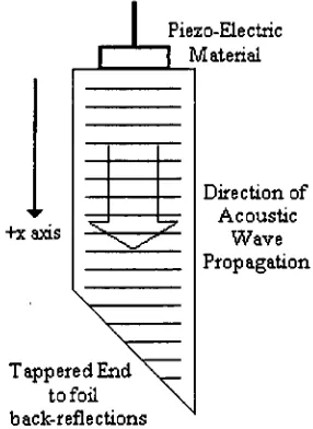
adopting a geometrical optics point ofview ofthe cell's operation. In this simplisticmethod of analysis, the acousto-optic cell may be looked at as a piece of material, the
transducer, into which an acoustic wave is introduced
by
the use of a piezo-electricmaterial, as showninthefigure below:
+xaxis
V
v
Piezo-Electric
1 Material
\
TapperedEnd
tofoil back-reflections
Figure8. Anacoustic wavepropagating inthe transduceroftheacoutso-optic cell.
Directionof
Acoustic
Wave
[image:34.557.208.351.428.624.2]Derivation
of
theExpected Acoutso-Optic Cell
Output:
Amplitude
Modulation
Theacoustic wave
traveling
inthe transducerisgivenby
theexpression6:s(x,t)=
S0cos(qx-L~lt)
(8)
2tc where Q.=
2nf
isthe angularfrequency
ofthe signal andq= is thewavenumber. In Athis case, the acoustic wave is propagating down (+x
direction)
the cell. The acousticwave
traveling
inthe transducerestablisheslocalizedchangesintheindexof refraction of the transducer proportional to amplitude of the acoustic wave. Under these conditions,the index of refraction in the transducer may be written as a function of spatial
coordinatesinthetransducerandtime7:
n(x,t)=
n-An0cos(qx-L~lt)
(9)
In order to simplify the determination of the interaction of light with the
time-varyingsinusoidal indexgrating,it is observedthat the optical
frequency
is much greaterthan the acoustic frequency. Under this condition, the periodic index structure will
appeartobealmost stationary with respect tothe light
during
the interaction8.Thus,
theindexof refraction ofthe transducermay bedescribedas:
n(x,t)=
n-An0cos(qx-0)
(10)
where O is the phase shift in the sinusoidal structure caused
by
taking
a"snap
shot"
ofthestructure at a particularpointintime.
Next,
considerilluminating
the transducerwith a plane wave that makes an angleof0with respectto theacousticwavefronts,as shownin Figure 9.
6B. SalehandM.CTeich,FundamentalsofPhotonics. (John
Wiley
&Sons, Inc.,New York 1991) Chap. 207B.SalehandM.CTeich,FundamentalsofPhotonics.(John
Wiley
&Sons,Inc.,New York 1991) Chap. 20+xaxis
-172
Lsinfl Lsinfl
Figure 9. Reflectionsof abeamoflightoff of a structurepossessinga periodicindexof refraction.
From a prior
knowledge,
the beam reflected off of the periodic structure is thebeam desired for analysis. It is assumed thatthe incidentwave is partially reflected
by
each periodin the transducer, due to the changing refractive index inthe transducer, and
that thereflectancedoes notsignificantlyreducetheamplitude ofthe transmittedlight9.
If Ar=
dr/
a* is the incremental reflectance at apoint x onthetransducer,then
the total reflectance overadistance L isgiven
by integrating
the infinitesimal reflectanceovertheilluminatedportion ofthetransducer:
ci/2 ., a dr
r=\ ej2kxsme^-dx
(11)
J"^2
OXwhere a phase
factor,
exp[y2fcsin0], has been introduced in order to account for thedifference in phase across the beam with respect to the x = 0 point. An expression for
dy,
may be foundby
consideringdy.
=dry dry
The expression for
dry
may be obtainedby
examining the expressions for thereflectanceinthe transducerwhenthelight incident iseitherintheTEorTMmode.
TM Case
In general, the expression for the Fresnel reflection coefficient,
describing
theportion oftheincidentelectricfieldreflected off a
boundary
interface,
isgivenby:_
,^2cos01-n1cos02
HjCOsOj+^COSOj
wherethedefinitionsofthequantitiesareshowninthefigure below:
(12)
Incident
Ray
SurfaceNormal ReflectedRay
Boundry
Refracted
Ray
Figure 10. Theangulardefinitionsrequiredintheanalysis oftheFresnelcoefficientsfortheTEandTM
cases.
When applying the formula to determine the reflectance from a period index
structure, the
following
values mustbe adopted: ni = n +An,
n2 = n,
Q\
= 7T./20,
andSnell's Law is requiredforthe determinationof02- Theorigin ofthese valuesis obvious
by
reviewing the situation. Upon substituting into the TM Fresnel reflection coefficientn-sin(9)-(n+-An)- |l
(th-An)
(n+ An)sin(9)-hn- \l
-(n-t-An)2
J
(13)
Anexpressionfortheincrementalchangeinrintermsof asmall changeinnmay
be found
by
writingtheFresnelcoefficient as aTaylorseries expansion,about0,
intermsofAnandextractingtermsontheorderofAn.
Thus,
anapproximationfor Arisgivenby;Ar= dr dAn An
(14)
An=0 Uponsubstituting:Ar =
L
(sinOJ-A/l-cosO)2)
1-cos(9)2|
/
-cos(e)2-Vi-
-cos(9)2-sin(9)+
\sin(e)-t-Vl-cos(9)2)
n-sin(9)-t-n"\/l-cos(9)
(15)
An
Simplifying
theexpressionutilizingtrigonometricidentities:
Ar:-1 /m2
/m (sin(0)-sin(9))
/
. ... 1 ...2 -cos(9) - sin(6)---sm(9)n cos(0)
sin(0) (sin(9)-i-sin(0)) sin(9)
(n-sin(9)-fn-sin(9))
An
(16)
Furthersimplification:
.._ sin(9)
Ar. An
2-n-sin(9)
(17)
Resulting
inafinalexpressionfortheinfinitesimalreflectionintheTM case:(18)
Ar= An
2sinz0 TECase
_
1cos01-n2cos02
(19)
HjCOsO^/^COSOj
Upon substituting in thevalues mentionedpreviously inthe evaluation ofthe TM
case:
rx =
(n-i-An)sin(9)-n- \l
-(n-i-An)
(n-i-An)-sin(9)-t-n- 1-
-(20)
(n-hAn)
Extracting
terms of the first order ofAn from the Taylor series expansion ofrxabouttheorigin:
dr Ar=
dAn
An
(21)
An=0
This leads to theexpression:
sin(9)
Ar:=
1 ...2 \sin(0)-Vl-cos(9)
'
, , . ...
cos(9) -- '~
sin(9) +
l-cos(9) sin(9)-i-A/l-cos(9) l-cos(9)
cos(9)
/
n-sin(9)+n-^/l -cos(9)
(22)
An
Theexpressionsimplifiesto:
Ar._l
>os(9)2-sin(9)2)
Ar 2
(-n-sin(0)2)
(23)
Theexpression yields afinalresultfortheinfinitesimalreflectionintheTEcase:
(24)
-cos20 .Ar= An
2sin20
By
utilizing the small angle approximation, cos20=l,
it can be seen that theresulting approximation formulas fromthe TE andTMreflection cases possess the same
Ar=
An
2wsin 0
(25)
Returning
to theexpression required fortheintegration,
the expressionfordry
7must be determined.
By
using the expression for the infinitesimal reflectance as afunctionofinfinitesimal indexchanges,an expressionfor
dry
may be derived:dr dr dn -1 d
dx dn dx 2nsin20c&c
dr -1
(n
-An0
cos(qx-O))
dx 2msin2 0
By
applying theidentity
that sin(;c)=reflectancefromthe
Bragg
cellbecomes:(26)
,qAn0sm(qx-<&)
(27)
the integral for the total eJX-e~JX
V
1 , v* fi/2
=jreJ
?J J-L/2
j(2ksin6-q)x
dx 1 , -/>
(LU
jr e J <
0J J-L/2
J{7ksia&+q)x
dx
Solving
forthefirst integral:(28)
2" i, T J eJ(2ksin6-q)x dx= 2j(2k%ixi-q)
2 2(29)
1 ;<j> r= jreJ a 2J j(2ksmB-q)^ -j(2ksind-q)^e 2 -e 2
ra =yr'e*
-sinc[(2Jfcsine
-q)]
(32)
2 2k
wheresinc(x)=
sin()/
. v '/tut
Therefore,
evaluationoftheentire reflectanceintegral leadsto:r =yrV<I,-smc[(2A:sin0-gr)]-jre'^
-smc[(2ksmQ+q)
]
(33)
2 2k 2 2k
Significance
of
theBragg
Angle
Since the maximum of the sine function occurs when the argument ofthe sine
function is zero, the resulting expression for the total reflectance will be at a maximum
when either 2sin0=
q or
2sin0
=-q. Underthecondition when 2sin0=q, thefirst
term ofthe expression dominates. This represents the
"up
shifted"case and corresponds
to the operating mode ofthe
Bragg
cell usedin the optical systemoperation. Anexplicitstatementofthe
Bragg
conditionis givenbelow:sin0s=^
2A(34)
sin0B =
^
=Xfsisnal
(35)
Derivation of
theExpected Acoutso-Optic Cell Output:
Frequency
Modulation
Another important resultthat can be seen from the reflectance term occurs when
the temporal dependenceofthereflectanceisreintroduced
by letting
O >L~lt:r= Lsinc[(q-2k
sinQ)]ejni
(36)
2 2k
Consider aplane wave incident on the
Bragg
cell at theBragg
angle. The outputE0Ul=rEin
(37)
Suppressing
the spatialdependence
ofthe inputelectricfield,
the output electricfield displaysajcottime dependence:
EoutocreJ(ap,"f
(38)
Substituting
inforthereflectance expression:Eout
oc-jr'Lsmc[(q-2ksmQ)]eja,ejm^(39)
2 2k
Again,
suppressingthenon-temporal relatedtermsfound intheexpression:0,~ey("+<W'
(40)
Fromthis result, itis apparent thatthe output fieldwillbe
frequency
shifted fromtheinputfield
by
the valueofthe acousticfrequency
foundinthe transduceroftheBragg
cell.
Thus,
if a plane wave is introduced into theBragg
cell at theBragg
angle (formaximum reflected output from the cell,) the acoustic signal
traveling
in the transducerwillbeplaced upon an optical carrier. The resulting
frequency
ofthe outputfield is givenby:
(0TOr=Q+(i)opllcal
(41)
RecoveryofAcousticSignal: Optical
Heterodyning
By
theprocess of optical heterodynedetection,
anRF signal thathas been placedon an optical carrier is recovered
by "beating
down" the optical carrier with anon-frequency
shifted reference beam. The process of signal recovery can be examinedby
consideringtheinterferenceofthetwobeamsat anopticalsquare-law detector.
The signal beam can be characterized as a plane wave of amplitude
As,
opticalfrequency
co0, and an RFfrequency
(ORp.Therefore,
the signal wave will possess theform:
,(0
=Os
represents a relative phase shift between the signal and the local oscillatorbeam.
Thereference,orlocaloscillator,wave will alsobea plane wave. Howeveritwill
onlyexhibitthe
frequency
oftheoptical carrier:LO(t)
=ALOexp[jG>0t]
(43)
Since bothbeams are coherent, the resulting
intensity
at the detectorwill be thesquare ofthemagnitudeofthesumofthewaveforms:
^(OH^O
+^otOf
(44)
whichmay bewritten as:
Id*
=%%
+*A
+^'lo
+%*u>
(45)
By
employingthewellknowntrigonometricidentity:eje+e'fi
cos0=
(46)
2
theform ofthe
intensity
atthe detectorisfoundtobe:IDel
=|^r+|Aor
+2A/|^|2|^o|2cos(((0o+(0^)/-{Do('+<&s)
(47)
Upon simplifying, theresulting form isshown
below,
IDe,
(0
=IS
+ho
+^hho
cos(co^r+Os
)
(48)
which indicates that the
intensity
pattern incident on the detector will vary in time at arate equal to the RF
frequency
placed onthe signalbeam,
with a phasedelay
equal to thephase
delay
presentin thesignalbeam. Sincethe electrical signalwill beproportional tothe
intensity
incidentonthesquare-lawdetector,
theRFsignal willberecovered.Atypical optical setupusedin theplacement and extraction of an RFsignal on an
Beamsplitter
Laser
Optical
Frequency
Shifter
Optical Phase
Shifter
Beamsplitter
/
M\Mirror N / Mirror
Figure11. Ablock diagramof atypicalscheme usedinheterodynedetection. Electrical
Signal
Various means may be used to place the RF signal on an optical carrier.
However,
in the case ofthe optical system only aBragg
will be considered.Also,
thepresence of an optical phase shifter, in the case of the integrated system, is rather
complex and willbe discussedlater.
TheConnectionBetweenHeterodyne SystemsandPhasedArravAntennas
From the classic heterodyne optical system, one can see a possible application of
technique tophased array antennas. Ifeach radiating elementof the antenna were to be
attached to an separate
heterodyning
system, the RF signal to be broadcast could beplaced upon the signal beam
(utilizing
the opticalfrequency
shifter) and then phaseshifted the amount neededin orderto steerthe beam in a particular direction. Some of
the problems that exist with such a configuration is the amount of space required for
configuration and the high price ofthe components required. The integrated system is a
novel way ofrealizing multiple
heterodyning
systems, possessing ahigh packingdensity
ofthe
delay
linesthatisnot presentinthemultiple system case.Dependence
of Output Angle
onAcoustic
Frequency
Upon varyingthe
frequency
of the acoustic wave in the cell, the deflection angleapproximationto the
Bragg
equation anddifferentiating
the output angle,0,
with respecttothesignal
frequency,
fsjg.^~Vsignal
A0=
-2nBraggVS
(49)
Operation
ofthe
Binary
Optic
Device
Ingeneral, a
binary
opticis an optical component on which asurfacereliefpatternhas beenetched thatwill result in phase shifts ofthe incidentbeam
by
values of0 or-K.The surface relief pattern is governed
by
the input and desired output field pair. Thebinary
optic deviceused in the integratedsystem has been designed tobreak an incidentplane wave into 25 equal
intensity diverging
plane waves, each beam will represent anindividual
delay
line. In order to confirm the operation ofthebinary
optic, the phasefunction ofthe surface was enteredinto aMATLAB program andthe magnitude squared
of the Fourier transform of the transmission function was found. The is analogous
examining the farfield
intensity
pattern thatresults when a plane wave is incidenton theBinary
Optic. A mesh and contour plot of the resultingintensity
pattern are shownbelow.
|2-D FFT|A2 of
binary
optictransmission function200
100
|2-D FFT|A2 of
binary
optictransmission function25 Equal
Intensity
Diffracted Orders
50 100 150 200 250
Figure 13. Acontour plot oftheresulting
intensity
pattern withtheBinaryopticis illuminateswith a uniform plane wave. Notethe25 distinctorders.Introduction
to the
Deformable
Mirror Device
(DMD)
The deformable mirror device is a two-dimensional array of electronically
controlled mirrors. Eachmirror may be addressed, controlling the X and Y tilt angle of
the mirrored surface.
Using
state-of-the-art technology, it is possible to generate devicepossess over one million mirror segments in an area of one square centimeter, with an
active
(reflecting)
area greaterthan70% ofthesurface10.10L.Hornbeck,"Deformable-MirrorSpatial LightModulators,"
ProceedingsofSPIE,Vol. 1150-1206.
IV.
Single
Photonic
Delay Line
Concept
Generation
ofaTrue Time
Delay
(TTD)
The time delays required for the operation of the phased array antenna are
obtained
by
actively selecting, ortapping,
points on aBragg
cell illuminatedby
acollimatedbeam. The source ofthe time delays canbe seen withthe aid ofthe diagram
shownbelow:
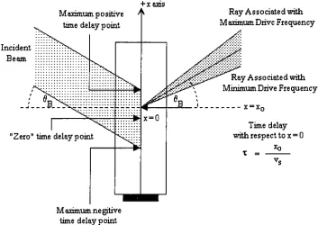
+xaxis
Maximumpositive A
time
delay
pointIncident
Beam
*
"Zero"
timedelaypoint
Ray
As s o ciatedwithMaximumDrive
Frequency
Ray
As s ociatedwithMinimumDrive
Frequency
x= xr
Time
delay
with respecttox=0
Maximum ne gitive
time
delay
pointFigure 14. TheBraggcell,
indicating
theregionfromwhichtimedelayscanbeselected and arayfanassociated with aparticulartimedelay. The illuminatedportion oftheBraggcelldefinestheregionfrom whichtimedelayscanbetapped.
In this case, the
Bragg
cell is illuminatedby
abeamofdiameter d andis drivenby
thedesired output signal oftheantenna. The availability of signaldelaysresults fromthe
finite time it takes the RF signal to propagate through the AO Cell across the beam
[image:47.557.103.456.242.492.2]illuminated
by
the source dividedby
the velocity of soundtraveling
in the transducermediumor:
D
.
co!ei=_D^
vs
vscos0flInordertomaintain somesymmetry intheopticalsystem, the"zero" time
delay
point waschosentobe thecenter oftheincidentillumination.
Therefore,
thepossibletime delays fall intherange of:
^
S,S+(51)
2vscos0B
2vscos0B
Aparticulartime
delay
value ofthesignal may bechosenby
"tapping" the outputface of the
Bragg
cell.Tapping
the cell may be interpreted as selecting out aninfinitesimally
smallarea(equivalentto adeltafunction)
from theilluminatedportion ofthe
Bragg
cell.By
tapping
the cell at a particularpoint,theresulting lightleaving
thecellfromthatpointwill serveas acarrier,carryingthesignal
frequency
aswell astheselectedtime delay. In Figure
14,
theBragg
cell isbeing
tapped at a point adistance ofx0 fromthe center(x=
0)
oftheincident beam.Thus,
thesignal placed onBragg
celltap
atx=x0willbeadvancedfromthesignal placed on abeamtappedat x=0
by
a value oftd
=+-e-seconds(52)
vs
As the signal propagatingthrough the
Bragg
cell varies, the outputbeam from theAOcell will be deflectedaccordingly. The highestandlowestfrequencies serveto define
aray fan thatwill be associated with a particulartime
delay
forall RF signal frequenciesGeneral Optical System for
Tapping
the
Photonic
Delay
Line
From the previous section, it is known that each particular time
delay
for allsignals can be looked at as
tapping
particular points of theBragg
cell.However,
theproblemofselecting a particularrayfan (time
delay)
forthepurposes ofbeating
downtorecoverthe time delayedsignalmustbeexamined.
A novel optical architecturehas been proposed
by
ZmudaandToughlian in orderto select particular ray fans (time
delays)
in order to recover the delayed signal11. Asimplified version (a driver for only one element of the antenna) of the
heterodyning
systemisshownbelow:
Splitter
Tiltable Mirror
Bragg
CellPositive Lens
Figure 15. Architectureofa single photonicdelay,as proposedbyZmudaandToughlian.
In theabovesystem, theray fans aretransformed into planer waves
by
the use of apositive lens that is placed suchthat its focal length is located atthe center ofthe
Bragg
cell.
Thus,
the positive lens serves to collimate the fans. Once the fans are collimated,each time
delay
is associated with aparticularplane wave ofa unique spatial frequency.nH.ZmudaandE.Toughlian, "Adaptive Microwave SignalProcessing:APhotonic
Solution,"
Microwave
In orderto select aparticular plane wave (time
delay,)
atiltable mirroris introduced intothe system.
By
controlling the tilt angle ofthe mirror differentpoints on theBragg
cellmaybe tappedas shown abovein Figure 15.
Thus,
by
adjustingthe angle ofthe mirror, aparticular location on the AO cell is selected, corresponding the to the selection of a
particular time
delay
forall signals. The selected plane wave isthen interfered with thelocal oscillator of the
heterodyning
system. In this system, the timedelay
becomes afunctionofthe tiltangle ofthe mirror andthefocallengthofthepositive lens used. The
appropriate mirror tiltangle associated with selecting a particulartime
delay
is givenby
the
formula12,
assumingthat the tiltangleoftheBragg
cellisnegligible:0m=|tan-l^
(53)
This formula is derived from the geometry of the system and considering the
reversibility oflight. Consider
tracing
a plane wave back through the system,traveling
normalto the face ofthe detector. Such a plane waveis associated withthe desiredtime
delay. Upon
tracing
theplane wavebackthrough the signal portionin the system, itwillbe brought to afocus at some point onthe
Bragg
cell, as shown in Figure 16. The pointselected onthe
Bragg
cell correspondstothedesiredtimedelay
extraction point.-X
Tiltable Mirror
BraggCell
Positive Lens
Figure 16. Geometryforthederivationof required mirrortiltangleintermsofthedesiredTTD.
12H.ZmudaandE.Toughlian,"Adaptive Microwave Signal Processing: APhotonicSolution,"
Microwave
In order to cause the signal beam to become parallel with the optical axis, the
mirror mustbe tilted at an angle of20. This is due to the law ofreflectivity,
0r
=0'r-Fromthe
diagram,
it isobviousthat thefollowing
relationshipexists:tan0=^ F
(54)
Ifthe center ofthe cell is assumed to bethe zero
delay
reference point, then thetime
delay
associated with x0 is simply the value of x0 dividedby
the velocity of thesignalpropagatinginthetransducer,or:
(55)
tan0=^iL
F
where
tj
isthetrue timedelay
ofthesignal.Recalling
thatthemirrortiltangle shouldbetwice the value of
0,
or20 =0m,
yieldsthe result shown previously for mirrortilt anglerequiredtoachieve a certaindelay:
0m
2
fv
VS tld\
V. Design
ofthe
Integrated
Photonic
Delay
Line System
The
Significance
ofRay
Fans
andDelay
Lines for System
Design
As stated in the previous section, ray fans are generated in the system
by
considering afixedpoint on the
Bragg
cell and varyingthedriving frequency
ofthe cellbetween thehighestandlowestRFvaluesinthe signal. The highest
frequency
will resultin thelargestpositive deflection ofthebeamfromthe
Bragg
angle, thus it willdefine theupperlimitoftheray fanasitexitsthe
Bragg
cell. The lowestfrequency
will resultinthegreatestnegativedeflection ofthebeam fromthe
Bragg
angle, thusdefining
the low limitofthe ray fanas itexitsthe
Bragg
cell. Sincearay fanis associated withafixed pointonthe
Bragg
cell,itisassociatedwitha specificTTD forallRF frequencies.Aphotonic
delay
line,
orsimplydelay
linefor short, is the superposition ofthe allpossibleray fans alongtheilluminatedregion ofthe
Bragg
cell.Therefore,
adelay
line iscomposedof all possible
delay
values. Aparticulardelay
value isselectedby
probingthedelay
linetoselectout a particularray fanassociated with a particularTTD. Thepurposeof the optics of the integrated system, and the simple system shown previously, is to
create a situation in which the individualrays fansare causedtoconverge in a mannerin
which the
delay
line may bemanipulated to extract a particularTTD value. In both theintegrated and the simple photonic
delay
line system all ray fans converge upon adeformable mirror
device,
which can select a particular ray fan(TTD)
for heterodynedetection (conversion ofthe optical signal to the desired delayed electrical signal) from
Underlying
Values Used for
Designing
Before
describing
how the system isdesigned,
it is importantto present some ofthefactors thatwillbeconsideredthroughoutthe design. The importanceofthesevalues
willbecomeapparentinthesystemdesign.
The laser source used in the systemis an IR source, operating at
1319nm,
whichhasan outputbeam diameterof0.6mm.
Unless otherwise stated, all glass components used in the system are fabricated
from BK7. At the particular wavelength of the laser to be used in the system, the
refractiveindexofBK7 is 1.50348. Therefractiveindexof airisconsideredtobe 1.0. The central RF operating
frequency
of theBragg
cell is 1.3*109 Hz. Thebandwidth ofthe system is 0.2* 10^
Hz,
resulting in the highest
driving frequency being
1.4*10^ Hzandthelowest
driving frequency
1.2*10^Hz.The index of refraction of the
Bragg
cell is 3.34. The distance that the activeregion ofthe cell occupies along theoptical axis ofthe systemis 5 mm. The velocityof sound propagating in the
Bragg
cell 5125 m/s. From these parameters, theBragg
anglemay be determined:
(l319*10-9m)(l.3*10V)
sin0B=-^ ^; - =0.1672878
(57)
B
{2)5\25mls
0B
=9.63016=0.16808rad(58)
The angular spread of a ray fan may be calculated from the bandwidth of the
system. The angular difference betweenthe an extreme RF
frequency
andthe central RFfrequency
isgivenby:A0=
^
=1^^(O.1*1OV)
(59)
"sound
5125%
A0=O.O257366rad
Simll: Computer
Simulation
andDesign
Tool
In this section, the name Simll will be mentioned several times in the
determination of componentspecifications. Simll is aprogram, written
by
the author, inorder to carry out a real ray
tracing
analysis of the integrated system, as well as otheroptical systems.
By
usingSimll information concerningtherelative displacement of raysat particular planes in the surface, i.e. a geometrical estimation ofbeam
diameters,
anddifference in optical ray slopes after surfaces, i.e. a measurement ofthe collimationofa
beam,
the performanceoftheoptical systembeing
designedcanbeevaluated. Simll hasalso has the capability to optimize optical component parameters, i.e. the thickness ofa
component, until the difference in slopes after a user designated surface falls within a
given tolerance. Suchanoptimizationisquiteuseful,removing fromtheuser theneedto
closely calculate component parameters to achieve well collimated beams. Since the
optimization is accomplished using real ray tracing, the error introduced from applying
paraxial methodsforthe calculationhas beenminimized.
Integrated System
Overview
The design ofthe integrated system is an extension ofthe single photonic
delay
line system shown earlier. The extension to the system is done in order to increase the
number of optical
delay
lines available and insure that each new individual opticaldelay
line is a reproduction ofthe singledelay
line associated with the "simple" system. Theinsertion of extra opticsbetweentheoutputofthefrontend ofthe systemandtheDMD is
requiredin orderto accomplish the replication ofthe
delay
line. Oncethedelay
line has beenreplicated, additional optics are furtherrequiredtoshapetheindividualdelay
lines.The integrated optical systemmay be looked at as
being
composed offour majorend,"
is to place the RF signal onto an optical carrier via an acousto-optic cell, to break
the input beam into reference and local oscillator
beams,
and to recombine the beamsafter the RF signal has been place on the optical carrier for later heterodyne detection.
The output