White Rose Research Online URL for this paper:
http://eprints.whiterose.ac.uk/124711/
Version: Accepted Version
Article:
Hu, Y., Zhu, Z.Q. orcid.org/0000-0001-7175-3307 and Odavic, M. (2017) Comparison of
two-individual current control and vector space decomposition control for dual three-phase
PMSM. IEEE Transactions on Industry Applications, 53 (5). pp. 4483-4492. ISSN
0093-9994
https://doi.org/10.1109/TIA.2017.2703682
© 2017 IEEE. Personal use of this material is permitted. Permission from IEEE must be
obtained for all other users, including reprinting/ republishing this material for advertising or
promotional purposes, creating new collective works for resale or redistribution to servers
or lists, or reuse of any copyrighted components of this work in other works. Reproduced
in accordance with the publisher's self-archiving policy.
[email protected] https://eprints.whiterose.ac.uk/ Reuse
Items deposited in White Rose Research Online are protected by copyright, with all rights reserved unless indicated otherwise. They may be downloaded and/or printed for private study, or other acts as permitted by national copyright laws. The publisher or other rights holders may allow further reproduction and re-use of the full text version. This is indicated by the licence information on the White Rose Research Online record for the item.
Takedown
If you consider content in White Rose Research Online to be in breach of UK law, please notify us by
Abstract -- The relationship between the two-individual current control and the vector space decomposition (VSD) control for a dual three-phase permanent magnet synchronous machine (PMSM) is investigated in this paper. It is found that the VSD control is more flexible on controlling the fundamental current in sub-plane and the fifth, seventh current harmonics in z1z2 sub-plane with different PI gains, while the
two-individual current control is comparable to the VSD control in having the same PI gains in the and z1z2
sub-planes. It is also found that the two-individual current control may have potential instability issues due to the mutual coupling between the two sets of three-phase windings. If the mutual coupling between the two sets is weak to some extent, then the two-individual current control could have the same dynamic performance as the VSD control without the stability issues. Experiments are conducted on a prototype dual three-phase PMSM to validate the theoretical analysis.
Index Terms--double d-q synchronous frame current control, double-star motor, dual three-phase, instability, two-individual current control, VSD control.
I. INTRODUCTION
Multi-phase machines have been extensively employed in various applications such as electric ship propulsion, locomotive traction, electric and hybrid electric vehicles, “more-electric” aircraft, and high-power industrial applications [1-3]. They provide outstanding advantages [4-8], such as reduced phase current rating and torque ripple; a lower DC-link harmonic current; smooth magneto-motive force (MMF); improved efficiency; excellent fault tolerant characteristics and higher reliability at system level.
One of the most studied multi-phase machines is the six-phase machine [9], which can be easily driven by two individual classical three-phase voltage source inverters (VSIs). According to the shifted angle between the two sets of three-phase windings, the six-phase machine can be classified as symmetrical (shifted by 0° or 60°) and asymmetrical (shifted by 30°) six-phase/dual three-phase machine. The asymmetric dual three-phase machine is more attractive than the symmetrical one due to the cancellation of 6th torque harmonic [10]. The typical VSI for the dual three-phase machine with two isolated neutral points is shown in Fig. 1 [10], where the machine has two sets of three-phase windings, one set is designated as ABC, and the other set is XYZ shifted by 30° electrical degrees.
6
s
[image:2.595.316.537.217.294.2]
Fig. 1 Asymmetrical dual three-phase drive system [10].
Numerous current control strategies have been developed for the dual three-phase drive system [4-7, 11-18]. Two of the most interesting and widely used strategies are the vector space decomposition (VSD) control [11, 13, 16, 17], which treats the machine as a six-phase machine, and the two-individual current control [4, 5, 7, 12], which treats the machine as two single three-phase machines.
Since there is no mutual coupling between the sub-plane and z1z2 sub-plane [11, 14] in the VSD control, the
currents in the sub-plane and z1z2 sub-plane can be
regulated separately. As the torque is only related to sub-plane, the VSD control can provide excellent dynamic torque performance without the influence of coupling voltages between two sets.
The two-individual current control is based on the double
dq synchronous frames model [4, 5, 7, 12], where there is mutual coupling between the two dq-synchronous frames. Instead of the six-phase VSI, PWM strategies[11, 19-21], and complex matrix transformation of VSD control, two individual commercial single three-phase VSI inverters can be employed to drive each set of single three-phase windings in the dual three-phase machine individually. The two-individual current control is a very practical method in industry applications as it duplicates the vector control for a single three-phase machine. Meanwhile, it has the inherent advantage of suppressing the current unbalance resulting from asymmetries between the two sets of three-phase windings [5] and excellent fault tolerance capability.
The manuscript is expanding work in [22], as introduced in [22], the two-individual current control may have instability issues. The conditions for safely supplying the dual three-phase induction machine by two PWM-VSIs is introduced in [23, 24], where it was concluded that the multi-star machine supplied by independent PWM-VSIs has instability issues if a strong magnetic coupling between each set exists. In [25], the designs of coil pitch and special slot shape for a dual three-phase induction machine were
Comparison of Two-Individual Current Control and Vector Space
Decomposition Control for Dual Three-Phase PMSM
Yashan Hu
University of Sheffield Mappin Street, Sheffield
S1 3JD UK [email protected]
Z. Q. Zhu
Fellow, IEEE University of Sheffield Mappin Street, Sheffield
S1 3JD UK [email protected]
Milijana Odavic
Member, IEEE University of Sheffield Mappin Street, Sheffield
investigated, in order to increase the mutual leakage inductance to reduce the current harmonics for safe operation. However, how weak the magnetic coupling can be while still operating at a safe level for individual current control was not discussed.
In this paper, the two-individual current control and VSD control for dual three-phase PMSM are compared and their relationship is revealed. Based on their relationship, the instability of the two-individual current control is investigated. Firstly, the mathematical model of dual three-phase PMSM for two-individual current control and VSD control are briefly introduced in Section II. The relationship between them is demonstrated in Section III. Then, the instability of the two-individual current control is analyzed in detail with the aid of relationship to the VSD control in Section IV. Experiments are conducted in Section 0 to verify the analyses.
II. MATHEMATICAL MODEL OF DUAL THREE-PHASE PMSM
A. Inductance Modeling of Dual Three-Phase PMSM
Assuming that the induced back electromotive force (EMF) is sinusoidal; eddy current and hysteresis losses, mutual leakage inductance, saturation, the harmonic components in self-inductances and mutual inductances with orders higher than the second order [15] are neglected, the self-inductance can be expressed as
cos(2 )
PP sl dqavg dqdiff P
L L L L (1)
where
( ) / 2, ( ) / 2
dqavg d q dqdiff d q
L L L L L L (2)
The mutual inductance between phases in each set can be expressed as
cos( ) cos( )
PQ dqavg P Q dqdiff P Q
M M M (3)
The mutual inductance between phases in different set of windings can be expressed as
12 cos( ) 12 cos( )
PQ dq avg P Q dq diff P Q
M M M (4)
where P stands for phase A, X, B, Y, C, or Z, while Q stands for another phase that is different with phase P. P and Q are
the electrical angle of phase P and Q winding axis shifted from d-axis of PM rotor. Lsl is the phase leakage inductance,
(Lsl+Ld) and (Lsl+Lq) are the phase self-inductances when the
phase winding axis are aligned with d-axis and q-axis of PM rotor respectively. Mdqavg and Mdqdiff are the gains of DC and
second harmonic components in the mutual inductances between phases in each set. Mdq12avg and Mdq12diffare the gains
of DC and second harmonic components in the mutual inductances between phases in different sets
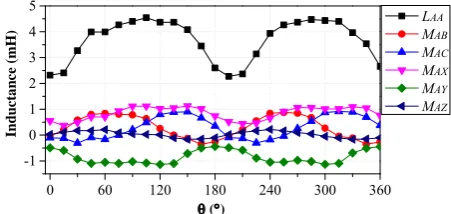
The measured self-inductances and mutual inductances of the prototype dual three-phase machine are shown in Fig. 2. After the FFT analyses of the measured inductances, it can be found that the dc components and 2nd harmonic components are dominant, which is in accordance with the inductance modeling(1), (3) and (4).
B. Two-Individual Single Three-Phase Model
The dual three-phase PMSM is considered as two single three-phase machines with mutual coupling [4]. The voltage equations for each single three-phase machine in dq-frame can be expressed as (5) and (6).
0 60 120 180 240 300 360 -1
0 1 2 3 4 5
In
d
u
ct
an
ce (m
H
)
()
LAA
MAB
MAC
MAX
MAY
[image:3.595.315.541.59.166.2]MAZ
Fig. 2 Measured self- and mutual inductances of prototype PMSM.
1 1 1 1 1
1 1 1 1 1
21 2 21 2
21 2 21 2
coupling voltages caused by another set
0 0
0
0
0
d s d d q q
q q q d d fd
d d q q
q q d d
v R L s i L i
v R L s i L i
M s i M i
M s i M i
(5)
2 2 2 2 2
2 2 2 2 2
12 1 12 1
12 1 12 1
coupling voltages caused by another set
0 0
0
0
0
d s d d q q
q q q d d fd
d d q q
q q d d
v R L s i L i
v R L s i L i
M s i M i
M s i M i
(6)
where the subscripts 1, 2 stand for set of windings identified by phase ABC and XYZ, respectively; vd1, vq1, vd2 and vq2 are
dq-axis voltages, id1, iq1, id2, iq2are dq-axis currents; Md21 and
Md12 is the mutual inductances between the d-axis in each
set, Mq21 and Mq12 is the mutual inductances between q-axis
in each set; Rs is the stator winding resistance; is the
electrical speed; fd is d-axis PM flux.
According to (1)-(4), the inductances in dq-framefor each set of single three-phase machines can be expressed as
1 2
1 1
2
2 2
d d sl dqavg dqavg dqdiff dqdiff
L L L L M L M (7)
1 2
1 1
2
2 2
q q sl dqavg dqavg dqdiff dqdiff
L L L L M L M (8)
21 12 3 12 12 / 2
d d dq avg dq diff
M M M M (9)
21 12 3 12 12 / 2
q q dq avg dq diff
M M M M (10)
If there is no mutual coupling between two sets, Mdq12avg
and Mdq12diff will be zero, therefore, Md21, Md12, Mq12 and Mq21
will be zero too, so as the mutual coupling voltages in (5) and (6). If there is full mutual coupling between two sets and between phases in each set, i.e. the Mdqavg and Mdq12avg are
equal to Ldqavg, the Mdqdiff and Mdq12diff are equal to Ldqdiff, then
(7)-(10) can be simplified as (11)-(14). In this case, there are large mutual coupling voltages in (5) and (6).
1 2 3 / 2
d d sl d
L L L L (11)
1 2 3 / 2
q q sl q
L L L L (12)
12 21 3 / 2
d d d
M M L (13)
12 21 3 / 2
q q q
M M L (14)
C. VSD Model
voltage equations in dq-frame in sub-plane and dqz-frame in z1z2 sub-plane can be expressed as (15) and (16)
respectively.
0 0
equ equ
d s d d q q
equ equ
q q q d d fd
v R L s i L i
v R L s i L i
(15)
0
0
dz s dz dz qz qz
qz qz qz dz dz
v R L s i L i
v R L s i L i
(16)
where the equivalent inductances in dq-frameand dqz-frame can be expressed as (17)-(20) when the inductances of dual three-phase PMSM are modeled as (1)-(4) [15].
1 12 2 21
equ
d d d d d
L L M L M (17)
1 12 2 21
equ
q q q q q
L L M L M (18)
1 12 2 21
dz d d d d
L L M L M (19)
1 12 2 21
qz q q q q
L L M L M (20)
As can be seen from (15) and (16), there are no mutual coupling voltages between dq-frame and dqz-frame. The VSD control can be shown in Fig. 3 [26].
* d i * q i , ,
a b c
i i i
, ,
x y z
i i i
6
[ ]T 1 z
i
2 z i q i * d v * q vi
i
d i 0 dzi
* v * v * 2 Z v * 1 Z v * 1 0 O v * 2 0 O v
i
i
qz i dzi
i
z12 z i dqz T 1 dqz T 0 qz
i
1 6
[ ]T
[image:4.595.59.290.95.156.2]* a v * b v * c v * x v * y v * z v * dz v * qz v 1 o i 2 o i
Fig. 3 VSD control [26].
III. RELATIONSHIP BETWEEN TWO-INDIVIDUAL CURRENT CONTROL AND VSD CONTROL
According to the vector control theory for single three-phase machine and the VSD control for dual three-three-phase machines (detailed in the Appendix), it can be deduced that the variables in the dual three-phase machine and in each set of the single three-phase windings have the following relationship considering (6k±1)th, k噺1, 3, 5… harmonics.
1 2
( ) / 2
dq dq dq
F F F ; Fdqz ( Fdq1Fdq2) / 2 (21) where Fdq1=[Fd1Fq1]T, Fdq2=[Fd2Fq2]T are dq-axis currents or
voltages in dq-frame for phase ABC and XYZ respectively.
Fdq=[Fd Fq]T, Fdqz =[FdzFqz]T are dq-axis currents or voltages
in dq- and dqz-framein the dual three-phase system. (21) means the currents or voltages in dq- and dqz-frames in a dual three-phase system can be obtained from the dq -axis currents or voltages in the single 3-phase ABC and XYZ; and vice versa, the dq-axis currents or voltages in single 3-phase ABC and XYZ can be derived from the currents or voltages in dq- and dqz-frames in a dual three-phase system, which can be expressed as
2
dq dq dqz
F F F ; Fdq1FdqFdqz (22)
Usually, the PI controllers should be tuned on their respective plants. However, the first and the second set of three-phase windings are identical and their respective plants are the same. Therefore, the current controllers for each set in the two-individual current control have the same proportional and integral (PI) gains. The outputs of PI controllers can be expressed as
*
1 1
i
dq p dq dq
k
v k i i
s
(23)
*
2 2
i
dq p dq dq
k
v k i i
s
(24)
where idq* means the dq-axis reference currents for each set,
idq1 denotes the dq-axis currents in the first set of single
3-phase ABC, idq2 denotes the dq-axis currents in the second
set of single 3-phase XYZ.
According to (22), (23) and (24) can be re-written as
*
1 0
i i
dq p dq dq p dqz
k k
v k i i k i
s s
(25)
*
2 0
i i
dq p dq dq p dqz
k k
v k i i k i
s s
(26)
Therefore, according to (21), the variables *
dq
v and *
dqz
v
in the dual 3-phase system can be expressed as (27) and (28) respectively.
* * * 1 2 / 2
i
dq dq dq p dq dq
k
v v v k i i
s
(27)
* * *
1 2 / 2 0
i
dqz dq dq p dqz
k
v v v k i
s
(28)
(27) and (28) are exactly the current controllers in
dq-frame in sub-plane and in dqz-frame in z1z2 sub-plane,
shown respectively in Fig. 3. They have the same PI gains in sub-plane and z1z2sub-plane. The above analysis shows
that the two-individual current control is equivalent to the VSD control with the same PI gains for the current controllers in both sub-plane and z1z2 sub-plane.
The two-individual current control can be illustrated in Fig. 4 [7]. The relationship of two-individual current control and VSD control can be demonstrated in the dashed box in Fig. 4. For two-individual current control, the part in the dashed box can be treated as a dual 3-phase machine. The inputs are the dq-axis voltages and outputs are dq-axis currents in each single 3-phase system.
1 dq
i
2 dq i i p k k s * 2 dq v * 1 dq v * * 1 2 2 dq dq dq v vv
* * 1 2 2 dq dq dqz v v
v
1 2 0
o o
v
dq v dqz v 1 2 o o v dq i dqz i 1
dq dq dqz i i i
2
dq dq dqz i i i
1 dq i 2 dq i i p k k s * dq i 1 2 o o i
[image:4.595.48.279.301.480.2] [image:4.595.313.543.592.712.2]Considering the variables’ relationship between the single and dual 3-phase systems, (21) and (22), the dual 3-phase model in the dashed box in Fig. 4 can be further expanded according to the VSD theory. In the dashed box, the variables in the dq-frame in single 3-phase ABC and XYZ are converted to the variables in the -z1z2-o1o2 sub-planes in
the dual 3-phase system, where Vdq*, Vdqz* and Vo1o2* are the
reference voltages in -z1z2-o1o2 sub-planes respectively,
the outputs are currents idq, idqz, and io1o2 in -z1z2-o1o2
sub-planes respectively, and then they are converted to the currents in dq-frame in single 3-phase ABC and XYZ. It is worth noting that the currents in o1o2 sub-plane are zero as
the neutral points of the two sets of single 3-phase windings are not accessible.
IV. INSTABILITY ANALYSIS OF TWO-INDIVIDUAL CURRENT CONTROL
The currents in sub-plane are related to electromechanical energy conversion and the currents in z1z2
sub-plane make no contribution to torque generation [11]. If VSD control is employed, the PI gains should be tuned according to the respective plants in sub-plane and z1z2
sub-plane. However, if the two-individual controller is employed, as discussed in Section III, the two-individual control is equivalent to the VSD control having the same PI gains in sub-plane and z1z2 sub-plane. To guarantee the dynamical performance of the two-individual current control, the PI gains should be optimized for its equivalent current controllers in sub-plane in VSD control. Since its equivalent current controllers in z1z2 sub-plane in VSD share
the same PI gains as that in sub-plane, the proportional gain may be relatively large in z1z2 sub-plane and cause
instability.
The equivalent inductances in sub-plane (17)(18) and those in z1z2 sub-plane (19)(20) are usually different due to
the mutual coupling. For example, if there is full mutual coupling between the two sets and full mutual coupling between phases in each set, i.e. Mdqavg and Mdq12avg is equal to
Ldqavg, the Mdqdiff and Mdq12diff is equal to Ldqdiff, (17)-(20) can
be simplified as
3 , 3 .
equ equ
d sl d q sl q
L L L L L L (29)
dz qz sl
L L L (30)
From (30), it can be seen that the inductances in z1z2
sub-plane are only related with self-leakage inductance in this case, which may be far less than the inductances (29) in sub-plane.
Neglecting the coupling voltages between the d-axis and
q-axis in dq-frameand the coupling voltages between the dz -axis and qz-axis in dqz-frame, the mathematical model in dq-
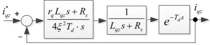
and dqz-frames shown in (15) and (16) can be simplified as a RL load [27, 28]. Then the current controller in dq- and
dqz-frame can be simplified as Fig. 5.
1
s
LsR d
T s
e
*
i i
i
p k k
s
[image:5.595.321.534.632.678.2]
Fig. 5 Typical current control scheme.
In Fig. 5, Td is the total delay time, which includes current
sampling delay, PWM output delay, etc. To simplify the design of PI gains, the delay function eT sd is usually
simplified to a low-pass filter 1/(1+sTd) [28, 29]. If the
dominant pole of –Rs/L is canceled by the zero point of the PI
controller, the open loop of the whole system can be simplified as a typical first order system , then Kp and Kican
be optimally designed as [29]
2 ; 2
4 4
s
p i
d d
R L
K K
T T
(31)
where is the damping factor, it is usually 0.707 for an acceptable rising time and overshot simultaneously.
When the PI gains of the two-individual current control are optimized for its equivalent current controllers in sub-plane in VSD, the PI gains for iq current controller will be
2 , 2
4 4
equ
q s
p i
d d
L R
K K
T T
(32)
If the PI gains are optimized for its equivalent current controllers in z1z2 sub-plane, the PI gains for iqz current
controller should be
2 , 2
4 4
qz s
p i
d d
L R
K K
T T
(33)
Define the ratio rd and rq as below
12 2 1
equ
d d
d
dz dz
L M
r
L L
(34)
12 2 1
equ
q q
q
qz qz
L M
r
L L
(35)
From (34) and (35), it can be seen that rd and rqincrease
as Md12 and Mq12 increase, which means the ratio rd and rq
will increase as the level of mutual coupling between the sets of three-phase windings increases.
If the PI gains for the two-individual current control loops are chosen for optimizing dynamic performance, the PI gains should be obtained from (32) for its equivalent q-axis current controller in sub-plane. Since its equivalent current controllers in z1z2 sub-plane share the same PI gains
as its equivalent current controllers in sub-plane, Kp for
the equivalent iqz current controller in z1z2 sub-plane can be
rewritten as (36), which is increased up to rq times of that in
(33).
2 2
4 4
equ
q q qz
p
d d
L r L
K
T T
(36)
Therefore, the equivalent iqz current control for
two-individual current control can be illustrated as Fig. 6.
1
qz s
L sR d
T s
e
*qz
i iqz
2 4
q qz s
d
r L s R
T s
Fig. 6 Equivalent current control structure for iqz.
To analyze the close loop root locus as the rqincreases,
d
T s
[image:5.595.57.274.682.718.2]than the low-pass filter approximation. Then the close loop transfer function in Fig. 6 will be
2
2
1 ( )
( ) 4
( )
1 ( )
1
( ) 4
q qz s
qz s
d
q qz s
qz s
d
r L s R M s
L s R N s
T s G s
r L s R M s
L s R N s
T s
(37)
The Eigen function of G(s) in (37) can be expressed as (38), which can be rewritten as (39).
2
2
( ) 4 ( ) ( ) ( )
= ( ) 4 ( ) ( ) ( ) 0
d qz s q qz s
q qz d qz s s
D s T s L s R N s r L s R M s
r L sM s T s L s R N s R M s
(38)
2
( )
1 0
4 ( ) ( ) ( )
q qz
d qz s s
r L sM s
T s L s R N s R M s
(39)
According to (39), the current controller with the same Eigen function as that in Fig. 6 can be shown in Fig. 7. As the close loop transfer function in Fig. 6 and Fig. 7 have the same Eigen function, they have the same root locus. In Fig. 7, the rq becomes the gain of the forward path, which is helpful
to analyse the root locus.
*
qz
i
iqz2
( )
4 ( ) ( ) ( )
qz
d qz s s
L sM s
T s L s R N s R M s
q
[image:6.595.50.274.315.358.2]r
Fig. 7 Current control with same Eigen function
In the following analysis, the second order Padé approximation is adopted. The root locus of iqz current
control can be shown in Fig. 8, when Td is 2e-4s. It can be
seen that all the poles are located in the left side of the plane when rq is equal to 1. However, when rq increases to the
critical value 3.3, one pair of poles are located on the image axis, which means the system is in a critical stable state. As
rq continues to increase, the pair of poles will cross over the
image axis, which means that the system tends to be unstable when the level of mutual coupling increases.
From the above analysis, it can be concluded that rq in (35)
should be lower than the critical value to guarantee the stable operation of the two-individual current controllers without compromising the dynamic torque performance, therefore the mutual inductance between the two sets should be carefully considered for the machine design.
-6 -4 -2 0 2
x 104 -1.5
-1 -0.5 0 0.5 1 1.5x 10
4
Real Axis
Im
a
g
Ax
is r = 1q
-6 -4 -2 0 2
x 104 -1.5
-1 -0.5 0 0.5 1 1.5x 10
4
Real Axis
Im
a
g
Ax
is r =3.3q
[image:6.595.313.545.399.479.2](a) rq = 1 (b) rq = 3.3 Fig. 8 Root loci of iqz current control.
It is worth noting that the accuracy of the root locus is also related to the accuracy of Lqz, R and d
T s
e , therefore, the precise critical value may be slightly different to the critical value of 3.3 in Fig. 8(b) due to the inaccuracy of the parameters and Padé approximation. However, the trend of poles of close loop transfer function moving towards to the right plane as rq increases is definitive.
V. EXPERIMENTS
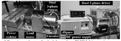
The hardware platform based on dSPACE DS1005 is shown in Fig. 9. The power topology is the same as Fig. 1, which has two individual single three-phase VSIs. The prototype dual 3-phase PMSM, whose design parameters are shown in TABLE I, is coupled to a PM dc machine used as an adjustable load by adjusting the power resistor. The execution rate of the current loop, current sampling frequency, and PWM frequency is configured to be 10 kHz. Two independent SVPWM modulators are employed for PWM generation for each channel.
Three experiments are conducted in this section. The first verifies that the two-individual current control is equivalent to the VSD control having the same PI gains for both and
z1z2 sub-planes. The second demonstrates the potential
instability of the two-individual current control. The third shows that the two-individual current control has the same dynamic torque performance as VSD control when it is in safe operation with PI gains optimized for its equivalent current controllers in sub-plane in VSD control.
Fig. 9 Experimental setup for dual three-phase PMSM drive testing.
TABLE IPARAMETERS OF PROTOTYPE DUAL THREE-PHASE PMSM
Parameters Value Resistance ( ) 1.1 Equivalent d-axis inductance in sub-plane Ld equ (mH) 4.58
Equivalent q-axis inductance in sub-plane Lq equ (mH) 5.19 Equivalent d-axis inductance in z1z2 sub-plane Ldz (mH) 2.42 Equivalent q-axis inductance in z1z2 sub-plane Lqz (mH) 1.44
rd (Ld equ / Ldz) 1.90
rq (Lq equ / Lqz) 3.60
No-load flux linkage (Wb) 0.075
Pole pairs 5
DC-link voltage(V) 40
A. Two-Individual Current Control and VSD Control
In this experiment, the drive works in constant current control mode, the iq reference is 1A. The currents under the
two-individual current control with PI gains optimized for current controller in sub-plane in VSD control are shown in Fig. 10(a). The currents under the VSD control with the same PI gains for both and z1z2 sub-planes are shown in
[image:6.595.308.552.509.618.2] [image:6.595.46.290.593.713.2]that they have the same spectrum, which means the two-individual current control is equivalent to the VSD control in this case.
-1.50 -0.75 0.00 0.75 1.50
-1.50 -0.75 0.00 0.75
0.00 0.05 0.10 0.15 0.20
-0.05 0.00
Cu
rrent (A
) ia
ix
Cur
re
n
t (
A
) i
i
Cu
rre
n
t (A
)
Time (s)
idz iqz
(a) Two-individual current control with PI gains optimized for sub-plane
-1.50 -0.75 0.00 0.75 1.50
-1.50 -0.75 0.00 0.75
0.00 0.05 0.10 0.15 0.20
-0.05 0.00
Cu
rre
n
t (A
) ia
ix
C
u
rr
en
t (A
) i
i
Cu
rre
n
t (A
)
Time (s)
idz iqz
(b) VSD control with same PI gains for both and z1z2 sub-planes as those in two-individual current control
-1.50 -0.75 0.00 0.75 1.50
-1.50 -0.75 0.00 0.75
0.00 0.05 0.10 0.15 0.20
-0.05 0.00
Cu
rre
n
t (A
) ia
ix
C
u
rr
en
t (A
) i
i
Cu
rre
n
t (A
)
Time (s)
idz iqz
[image:7.595.59.275.106.270.2](c) VSD control with PI gains optimized for and z1z2 sub-planes respectively
Fig. 10 Current profile comparison of two-individual current control and VSD control.
If the PI gains in the VSD control are optimized for the current controllers in and z1z2 sub-planes respectively, the
experimental current is shown in Fig. 10(c), and the corresponding harmonic analyses are shown in Fig. 11(c). It
shows that the peak value of idz and iqz are slightly higher
than that in Fig. 10(a) and (b). This is because a smaller Kp
(due to Lqz < Lqequ and Ldz < Ldequ) is applied when PI gains
are optimized for the current controller in z1z2 sub-plane
according to (31).
It is worth noting that although the references of idz and iqz
are zero in Fig. 3, idz and iqz are not zero and the amplitudes
are relatively large. This is because there are the 6th harmonic currents in idz and iqz due to the 5th and 7th harmonics in the
back-EMF and the inverter non-linearity, etc. The DC components can be regulated to zero by a PI controller. However, the 6th harmonic currents can only be suppressed rather than eliminated by PI controllers.
As demonstrated in the above three tests, it can be concluded that the VSD control is more flexible than the two-individual current control because the currents in and z1z2 sub-planes can be controlled separately and the PI gains for current controllers in each sub-plane can be optimized individually.
0 2 4 6 8 10 12 14 16 18 0.00
0.01 0.02 0.4 0.8 1.2
H
arm
oni
c c
urre
n
t(A
)
Harmonic order
i
i
idz iqz
(a) Two-individual current control with PI gains optimized for sub-plane
0 2 4 6 8 10 12 14 16 18 0.00
0.01 0.02 0.4 0.8 1.2
H
arm
oni
c c
u
rr
en
t(
A
)
Harmonic order
i
i
idz iqz
(b) VSD control with same PI gains for both and z1z2 sub-planes as those in two-individual current control
0 2 4 6 8 10 12 14 16 18 0.00
0.01 0.02 0.4 0.8 1.2
H
arm
oni
c c
u
rr
en
t(
A
)
Harmonic order
i
i
idz iqz
(c) VSD control with PI gains optimized for and z1z2 sub-planes respectively
Fig. 11 Current harmonics comparison of two-individual current control and VSD control.
B. Potential Instability of Two-Individual Current Control
When the PI gains in the current controller in the z1z2
sub-plane are optimized according to (31) by using inductances
Ldz and Lqz, the equivalent rd and rq are equal to 1. In this
case, the currents of idz and iqz at the ready state operation are
shown in Fig. 10 (c). However, when the PI gains in the current controller in the z1z2 sub-plane are chosen to be the
same as that in the sub-plane, rd and rq will be equal to 1.9
and 3.6 respectively. In this case, the currents of idz and iqz at
[image:7.595.57.276.485.649.2]The step current responses of idz and iqz in VSD control
are shown in Fig.12 (a) and Fig.12 (b) respectively. Although the current amplitude of idz and iqz at the ready state operation
in Fig. 10(a) and (b) are lower than that in Fig. 10(c), it is evident that there are more oscillations in the step current response when rq and rd are bigger than 1. Since the ratio rq
(=3.6) is larger than rd (=1.9), the oscillations in Fig.12 (b) is
larger than that in Fig.12(a), which means the iqz current
controller tends to be more unstable than the idz current
controller in this case study.
-0.002 0.000 0.002 0.004 0.006 0.008 0.010 0.5
1.0 1.5 2.0 2.5 3.0
Cu
rren
t (A)
Time (s)
rd = 1.9 rd = 1
(a) idz step response
-0.002 0.000 0.002 0.004 0.006 0.008 0.010 0.5
1.0 1.5 2.0 2.5 3.0
Cu
rre
nt
(A)
Time (s)
rq = 3.6
rq = 1
[image:8.595.53.280.185.356.2](b) iqz step response Fig.12 Step current response of idz and iqz.
When Kp for the two-individual current controller is
increased to 1.25 times of the proportional gain optimized for the current controller in the sub-plane (32), the equivalent gain rq of the forward path in Fig. 7 for current
controller in dqz-frame will be increased to 4.5. The equivalent rq is larger than the critical value 3.3 in Fig. 8(b)
(this may be inaccurate due to inaccurate parameters and approximation). In this case, the iqz current controller tends to
be unstable. The steady current under the two-individual current control is shown in Fig.13. It can be seen that the iqz
current controller tends to be unstable, while the idz current
controller and the current controllers in dq-frame in sub-planeare still stable.
-1.50 -0.75 0.00 0.75 1.50
-1.50 -0.75 0.00 0.75
0.00 0.05 0.10 0.15 0.20
-0.4 -0.2 0.0 0.2
Cu
rre
n
t (A
) ia
ix
C
urr
ent (A)
i
i
Cu
rre
n
t (A
)
Time (s)
idz iqz
Fig.13 Experiments of current steady response assuming rq = 4.5.
This experiment indicates that the two-individual current control may have potential instability issues if the actual rq is
larger than the critical value. To avoid the potential instability, Kp for two-individual control should be reduced,
and consequently, the torque dynamic performance will be compromised. Therefore, if the mutual coupling between the two sets of the dual three-phase machine is not designed properly, the current control stability and torque dynamic performance may not be guaranteed at the same time. If there is strong mutual coupling between two sets and the two-individual current control has to be employed, the PI gains can be tuned according to the current response in the sub-plane without causing the instability issues in the z1z2
sub-plane.
C. Comparison of Dynamical Performance
The torque dynamic performance of the two-individual current control and the VSD control are compared by step iq
current responses. The PI gains for the VSD control are optimized individually according to (31), whilst two-individual current control has the same PI gains as the current controller in sub-plane in VSD control.
The current reference is stepped from 0.5A to 1.5A at the time of 0s. The q-axis current feedback with VSD control and two-individual current control are shown in Fig. 14. It is evident that they have the equivalent iq response, which
indicates that they have the same torque dynamic performance. Therefore, if there is very strong mutual coupling between the first set and second set, the VSD control should be employed to guarantee the dynamic performance. However, if there is weak mutual coupling between the two sets, both two-individual current control and VSD control can be employed, depending on the practical implications of the application it is to be utilised for.
-0.002 0.000 0.002 0.004 0.006 0.008 0.010 0.25
0.50 0.75 1.00 1.25 1.50 1.75
C
u
rren
t (A)
Time (s)
[image:8.595.316.540.460.530.2]iq@VSD iq@2-Individual
Fig. 14 Comparison of dynamic performance.
VI. CONCLUSIONS
The two-individual current control and the VSD control for dual three-phase PMSM are compared and their relationship is revealed. The potential instability of the two-individual current control resulting from the mutual coupling between two sets of phase windings in the dual three-phase machine has been investigated. If the mutual coupling between two sets is weak, both the two-individual current control and VSD control can be employed. If the two-individual current control has to be employed in industry, to avoid the potential instability of the two-individual control, the ratio of the equivalent inductances in dq-frameand dqz -frame should be kept below a certain acceptable level, which provides the design criterion for mutual coupling between the two sets.It can be concluded that:
[image:8.595.58.273.548.711.2]in both and z1z2 sub-planes;
b) The two-individual current control has potential instability issues when there is a strong mutual coupling between the two sets of single three-phase windings;
c) The two-individual current control could have the same dynamic performance as the VSD control without stability issues if the mutual coupling between two sets is weak to some extent.
VII. APPENDIX A
VSD CONTROL FOR DUAL THREE-PHASE MACHINE Equation Section (Next)
According to VSD theory [11], the six-dimensional machine system can be decomposed into three orthogonal sub-spaces, i.e. , z1z2, o1o2 sub-planes. By the
transformation matrix(A1), different harmonics are mapped to different sub-planes. The fundamental and (12k±1)th, k噺1, 2… harmonics in real frame are mapped to sub-plane; the (6k±1)th, k噺1, 3, 5… harmonics in real frame are mapped to z1z2 sub-plane; the (3k)th, k=0, 1, 3, 5…
harmonics in real frame are mapped to o1o2 sub-plane.
1 2 1 2
6
T
z z o o
T
a x b y c z
F F F F F F
T F F F F F F
(A1)
where s = /6 and [T6] can be expressed as
61 cos( ) cos(4 ) cos(5 ) cos(8 ) cos(9 )
0 sin( ) sin(4 ) sin(5 ) sin(8 ) sin(9 ) 1 cos(5 ) cos(8 ) cos( ) cos(4 ) cos(9 ) 1
0 sin(5 ) sin(8 ) sin( ) sin(4 ) sin(9 ) 3
1 0 1 0 1 0
0 1 0 1 0 1
s s s s s
s s s s s
s s s s s
s s s s s
T
(A2)
By applying the standard Park transformation shown in (A3), the variables in sub-plane can be converted to dq
synchronous frame for dual three-phase system.
d dq q
F F
T
F F
;
cos sin
sin cos
dq
T
(A3)
The variables in z1z2sub-plane can be converted to a new
frame designated as dqz-frame by transformation as below [26].
1
2
dz z
dqz
qz z
F F
T
F F
;
-cos sin
sin cos
dqz
T
(A4)
where F is v, i, or , which correspond to voltage, current, and flux respectively. Then the (6k±1)th, k噺1, 3, 5… harmonics in z1z2 sub-plane are converted to (6k)th
harmonics in dqz frame.
REFERENCES
[1] E. Levi, "Multiphase electric machines for variable-speed applications," IEEE Trans. Ind. Electron., vol. 55, no. 5, pp. 1893-1909, 2008.
[2] E. Levi, "Advances in converter control and innovative exploitation of additional degrees of freedom for multiphase machines," IEEE Trans. Ind. Electron., vol. 63, no. 1, pp. 433-448, 2016.
[3] R. Bojoi, S. Rubino, A. Tenconi, and S. Vaschetto, "Multiphase electrical machines and drives: A viable solution for energy generation and transportation electrification," in Proc. International Conference
and Exposition on Electrical and Power Engineering (EPE), 2016, pp. 632-639.
[4] J. Karttunen, S. Kallio, P. Peltoniemi, P. Silventoinen, and O. Pyrhonen, "Dual three-phase permanent magnet synchronous machine supplied by two independent voltage source inverters," in Proc. Int. Symp. Power Electron., Electr. Drives, Autom. and Motion, 2012, pp. 741-747.
[5] G. K. Singh, K. Nam, and S. K. Lim, "A simple indirect field-oriented control scheme for multiphase induction machine," IEEE Trans. Ind. Electron., vol. 52, no. 4, pp. 1177-1184, 2005.
[6] R. Bojoi, A. Tenconi, G. Griva, and F. Profumo, "Vector control of dual-three-phase induction-motor drives using two current sensors," IEEE Trans. Ind. Appl., vol. 42, no. 5, pp. 1284-1292, 2006.
[7] R. Bojoi, M. Lazzari, F. Profumo, and A. Tenconi, "Digital field-oriented control for dual three-phase induction motor drives," IEEE Trans. Ind. Appl., vol. 39, no. 3, pp. 752-760, 2003.
[8] I. Zoric, M. Zabaleta, M. Jones, and E. Levi, "Techniques for power sharing between winding sets of multiple three-phase machines," in Proc. 2017 IEEE Workshop on Electrical Machines Design, Control and Diagnosis (WEMDCD), Nottingham, 2017.
[9] E. Levi, R. Bojoi, F. Profumo, H. A. Toliyat, and S. Williamson, "Multiphase induction motor drives - A technology status review," IET Electr. Power Appl., vol. 1, no. 4, pp. 489-516, 2007.
[10] K. Gopakumar, V. T. Ranganthan, and S. R. Bhat, "Split-phase induction motor operation from PWM voltage source inverter," IEEE Trans. Ind. Appl., vol. 29, no. 5, pp. 927-932, 1993.
[11] Y. Zhao and T. A. Lipo, "Space vector PWM control of dual three-phase induction machine using vector space decomposition," IEEE Trans. Ind. Appl., vol. 31, no. 5, pp. 1100-1109, 1995.
[12] Y. He, Y. Wang, J. Wu, Y. Feng, and J. Liu, "A simple current sharing scheme for dual three-phase permanent-magnet synchronous motor drives," in Proc. 25th Annu. IEEE Appl. Power Electron. Conf. and Expo., 2010, pp. 1093-1096.
[13] H. S. Che, E. Levi, M. Jones, W. P. Hew, and N. A. Rahim, "Current control methods for an asymmetrical six-phase induction motor drive," IEEE Trans. Power Electron., vol. 29, no. 1, pp. 407-417, 2014. [14] J. Karttunen, S. Kallio, P. Peltoniemi, P. Silventoinen, and O. Pyrhonen,
"Decoupled vector control scheme for dual three-phase permanent magnet synchronous machines," IEEE Trans. Ind. Electron., vol. PP, no. 99, pp. 1-1, 2013.
[15] S. Kallio, M. Andriollo, A. Tortella, and J. Karttunen, "Decoupled d–q model of double-star interior-permanent-magnet synchronous machines," IEEE Trans. Ind. Electron., vol. 60, no. 6, pp. 2486-2494, 2013.
[16] R. Bojoi, F. Farina, M. Lazzari, F. Profumo, and A. Tenconi, "Analysis of the asymmetrical operation of dual three-phase induction machines," in Proc. IEEE Int. Electron. Mach. and Drives Conf., 2003, pp. 429-435 vol.1.
[17] R. Bojoi, E. Levi, F. Farina, A. Tenconi, and F. Profumo, "Dual three-phase induction motor drive with digital current control in the stationary reference frame," IEE Proc. - Elect. Pow. Appl., vol. 153, no. 1, pp. 129-139, 2006.
[18] A. Galassini, A. Costabeber, C. Gerada, G. Buticchi, and D. Barater, "A modular speed-drooped system for high reliability integrated modular motor drives," IEEE Trans. Ind. Appl., vol. 52, no. 4, pp. 3124-3132, 2016.
[19] D. Yazdani, S. Ali Khajehoddin, A. Bakhshai, and G. Joos, "Full utilization of the inverter in split-phase drives by means of a dual three-phase space vector classification algorithm," IEEE Trans. Ind. Electron., vol. 56, no. 1, pp. 120-129, 2009.
[20] A. R. Bakhshai, G. Joos, P. K. Jain, and J. Hua, "Incorporating the overmodulation range in space vector pattern generators using a classification algorithm," IEEE Trans. Power Electron., vol. 15, no. 1, pp. 83-91, 2000.
[21] K. Marouani, L. Baghli, D. Hadiouche, A. Kheloui, and A. Rezzoug, "A new PWM strategy based on a 24-sector vector space decomposition for a six-phase VSI-Fed dual stator induction motor," IEEE Trans. Ind. Electron., vol. 55, no. 5, pp. 1910-1920, 2008. [22] Y. Hu, Z. Q. Zhu, and M. Odavic, "Comparison of Two-Individual
Current Control and Vector Space Decomposition Control for Dual Three-Phase PMSM," in Proc. XXII Int'l Conf. on Electr. Mach.(ICEM), 2016, pp. 989-995.
[24] N. Moubayed, F. Meibody-Tabar, and B. Davat, "Study and simulation of magnetically coupled multi stator induction machine supplied by independent three phase voltage-source inverters," in IMACS, 1999, pp. 59-64.
[25] D. Hadiouche, H. Razik, and A. Rezzoug, "On the modeling and design of dual-stator windings to minimize circulating harmonic currents for VSI fed AC machines," IEEE Trans. Ind. Appl., vol. 40, no. 2, pp. 506-515, 2004.
[26] Y. Hu, Z. Zhu, and K. Liu, "Current Control for Dual Three-Phase Permanent Magnet Synchronous Motors Accounting for Current Unbalance and Harmonics," IEEE J. Emerg. Sel. Topics Power Electron., vol. 2, no. 2, pp. 272-284, 2014.
[27] T. M. Rowan and R. J. Kerkman, "A new synchronous current regulator and an analysis of current-regulated PWM inverters," IEEE Trans. Ind. Appl., vol. IA-22, no. 4, pp. 678-690, 1986.
[28] A. Galassini, A. Costabeber, M. Degano, C. Gerada, A. Tessarolo, and S. Castellan, "Distributed current control for multi-three phase synchronous machines in fault conditions," in Proc. 2016 XXII International Conference on Electrical Machines (ICEM), 2016, pp. 1036-1042.
[29] V. Blasko, V. Kaura, and W. Niewiadomski, "Sampling of discontinuous voltage and current signals in electrical drives: a system approach," IEEE Trans. Ind. Appl., vol. 34, no. 5, pp. 1123-1130, 1998. [30] K. J. Astrom, "PID controllers: theory, design and tuning," Instrument
Society of America, 1995.
[31] C. GLADER, G. Högnäs, P. Mäkilä, and H. Toivonen, "Approximation of delay systems—a case study," Int. J. of Control, vol. 53, no. 2, pp. 369-390, 1991.
Yashan Hu received the B.Eng. and M.Sc. degrees in Electronic and Electrical Engineering from the Northwestern Polytechnical University, Xi’an, China, in 2002 and 2005, respectively. He has been working toward the Ph.D. degree at the University of Sheffield, Sheffield, U.K., since Jun 2012.
From 2005 to 2012, he was with Delta Green Tech (China) Co., Ltd., Shanghai, China, Shanghai Yungtay Elevator Co. Ltd as a Research Engineer, and Shanghai Welling Motor R&D Centre as Project Manager. His research interests are control of electric drives.
Z. Q. Zhu (M’90–SM’00–F’09) received the B.Eng. and M.Sc. degrees from Zhejiang University, Hangzhou, China, in 1982 and 1984, respectively, and the Ph.D. degree from the University of ShefÞeld, ShefÞeld, U.K., in 1991, all in electrical engineering.
From 1984 to 1988, he lectured in the Department of Electrical Engineering, Zhejiang University. Since 1988, he has been with the University of ShefÞeld, where since 2000, he has been a Professor of electrical machines and control systems in the Department of Electronic and Electrical Engineering, and is currently the Head of the Electrical Machines and Drives Research Group. His current major research interests include the design and control of permanent-magnet brushless machines and drives for applications ranging from automotive to renewable energy.
Milijana Odavic (M’13) received the M.Sc. degree in electrical and electronic engineering from the University of Zagreb, Zagreb, Croatia, in 2004 and the Ph.D. degree from the University of Nottingham, Nottingham, U.K., in 2008.
In 2013, she became a Lecturer in Power Electronics in the Department of Electronic and Electrical Engineering at the University of Sheffield, Sheffield, U.K. Prior to joining the University of Sheffield, she was a Research Fellow in the Power Electronics, Machines and Control Group at the University of Nottingham and in the Department of Electric Machines, Drives and Automation at the University of Zagreb. Her current research interests include modelling and control of power electronics dominated micro-grids,
![Fig. 1 Asymmetrical dual three-phase drive system [10].](https://thumb-us.123doks.com/thumbv2/123dok_us/7757766.169100/2.595.316.537.217.294/fig-asymmetrical-dual-phase-drive.webp)
![Fig. 3 VSD control [26].](https://thumb-us.123doks.com/thumbv2/123dok_us/7757766.169100/4.595.48.279.301.480/fig-vsd-control.webp)