© 2018, IRJET | Impact Factor value: 6.171 | ISO 9001:2008 Certified Journal | Page 2416
Evaluation of Coupled Shear wall in High-Rise Building
Prof. P.S. Lande
1Vishal S. Ankalkote
21
Associate Professor, Department of Applied Mechanics, Government College of Engineering Amravati,
Maharashtra, India.
2
PG Student Structural Engineering of Applied Mechanics, Government College of Engineering Amravati,
Maharashtra, India.
---***---
Abstract
-Shear wall is a basic important structural component. These walls can be utilized for giving more strength & safety to the structure, when the structures are subjected to external loads, such as earthquake loads, wind loads etc. these type of walls, basically play the main role for the construction of a tall structure. Provision of a shear wall is the structural system composed of braced panels (also known as shear panels) to counter the effect of the lateral load acting on a structure. It will act as vertical cantilevers to give the essential stiffness in a building.In this paper, four different models were considered for analysis of coupled shear. These all models have modelled in E-Tabs 2015 software by considering all geometric property are same. For equivalent static analysis and response spectrum analysis E-TABS 2015 software is used. In the result Storey displacement, storey shear, storey stiffness, storey drift is studied for all models.
Key Words: Coupled shear wall, Coupling beams, E-TABS 2015, Storey shear, Stiffness, Storey displacement, Storey drift, lateral load, Natural period.
1. Introduction:
The growth of population and land shortage in fast growing city areas are the two major problems for all developing cities as well as countries. In order to mitigate these problems, the structural designer’s choice to high rise building, which is rapidly growing in number, with various architectural configurations and use of structural materials. Due to the earthquake large amount of damage occurred in high rise buildings. So, this particular incident has shown that designers should provide adequate earthquake resistant provision to the high-rise buildings in terms of planning, designing and detailing in buildings to withstand the effect of an earthquake. The use coupled shear wall in one the possible option in high rise building.
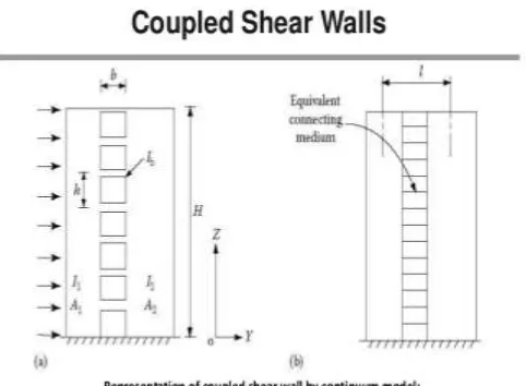
1.2 Coupled shear wall:
When two shear walls are interconnected by beams along their height then it is called as a coupled shear wall (as shown in fig.1). Coupling beams are the main key parameter in the coupled shear wall. These coupling beams are to be designed for ductile inelastic behaviour in order to dissipate
energy and provide damping during the earthquake. So, use of coupled shear wall is one of the potential options in comparison with special moment resisting frame(SMRF) and shear wall frame combination system in buildings. Shear and flexural behaviour are controlled by shear wall frame combination and SMRF systems whereas, the behaviour of coupled shear walls governed by flexural behaviour. However, behaviour of coupling beams is coupled shear wall is governed by shear capacity and behaviour of the conventional beam both SMRF and shear walls frame combination systems is governed by flexural capacity.
1.3 Coupling beams:
In multi-storey buildings, the lateral loads are resisted by shear walls due to their strength and stiffness. These walls have several openings such as windows, doors, elevators etc. which divide the whole shear wall into slender walls. To increase shear capacity these walls are interconnected by short beams along their height. These beams are called as coupling beams. Coupled shear wall system will give more economical as well as efficient structure systems than single shear wall systems also these systems possess higher stiffness, strength and energy dissipation. Design of coupling beam, there types and advantages are discussed as per ACI 318-11.
[image:1.612.326.567.504.681.2]© 2018, IRJET | Impact Factor value: 6.171 | ISO 9001:2008 Certified Journal | Page 2417
1.4 Need of Coupled Shear wall In Multi-storey Buildings:
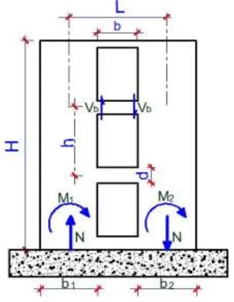
Fig.2) Section view of the coupled shear wall structure
In reinforced concrete high-rise structures, coupled wall structures as shown in Fig.2) can provide an efficient lateral load resisting system against wind and earthquake effects. When such structures are subjected to horizontal loading, the total overturning moment is divided into two components: primary bending moments, M1 and M2 taken by the individual walls and an axial bending moment Tl which is the axial force, T induced in the walls by the shear forces in the coupling beams, multiplied by a distance l between the neutral axes of the walls. The relationship between these two types of bending moment is given by single parameter. The degree of coupling (DOC) of coupled shear walls (CSW) is defined by the axial bending moment at the base of the structure, expressed as a fraction of the total overturning moment
Obtaining the different types of bending moment requires a full analysis of the structure as the relationship between these actions is dependent on the stiffness of the coupling beams. The continuous medium theory as applied to high-rise coupled shear wall structures allows a rapid assessment of the horizontal deflections when subjected to lateral loading. This makes it possible to derive expressions for the shear forces in the coupling beams in MSW structures. Establishing the maximum shear force, Vbmax in the critical coupling beam and its location up the height of the structure will yield a relationship between this peak shear force and an average shear force, Vb, average which is called the peak shear demand (PSD.
2. Related work:
Hoenderkamp (1): This paper presents a simple method of
analysis to determine the influence of single shear walls (SSW) on the degree of coupling(DOC)and on the peak shear demand (PSD) for beams of coupled shear walls (CSW) in mixed shear wall structures (MSW).
Harries et.al (2): An extensive parametric analysis of coupled
wall behavior was conducted. using elastic analysis and gross section properties, the role of representative geometric parameters in the response of coupled structures has been illustrated. The effect of using various code-prescribed reduced section properties is also discussed.
Subedi et.al (4): In this paper three basic modes of failurecan
be identified in reinforced concrete coupled shear wall structures, depending on the degree of interaction and the behavior of the coupling beams.
Rangolli and Hosur [11]: The growth of population and
shortage of land in town areas are two major problems for all developing countries. In order to mitigate these two problems, the designer’s choice to high-rise buildings, which are rapidly increasing in number, with various architectural configurations and use of structural materials. Due to frequent earthquakes occurring around the world, cause considerable damage to the large number of RCC high-rise buildings. This particular incident has shown that designers and structural engineers should ensure to offer adequate earthquake resistant provisions with regard to planning, design, and detailing in high rise buildings to withstand the effect of an earthquake. As an earthquake resistant system, the use of Coupled shear walls is one of the possible options.
3. Building parameter for modelling:
In this paper four different cases considered for analysis. Considering all geometric properties are same for all models and these models are modelled in E-tabs 2015 software as per structural details are given in Table.1
Table.1) Structural Details of RC Building
1 Type of structure Multistory rigid jointed plane
frame
2 Number of stories G+10
3 Floors height 3.5m
4 Size of column 550x550 mm
5 Size of beam 230x550 mm
6 Depth of slab 150 mm
7 Live load 1.On roof=1.5 KN/m2
2.On floor = 4 KN/m2
[image:2.612.88.258.116.335.2] [image:2.612.325.573.584.724.2]© 2018, IRJET | Impact Factor value: 6.171 | ISO 9001:2008 Certified Journal | Page 2418
9 Material M20 and Fe500
10 Grid lines (X) 5
11 Grid lines (Y) 5
12 Spacing along X and Y axis 5 m
13 Size of Coupling beam 230x1000 mm
14 Zone considered II
15 Importance factor 1
16 Response reduction factor 5
17 Damping Factor 0.05
18 Type of soil Hard
19 Wall load 17KN/m
20 Floor Finish 1.5 KN/m2
21 Response Spectra As per IS1893(Part1):2002
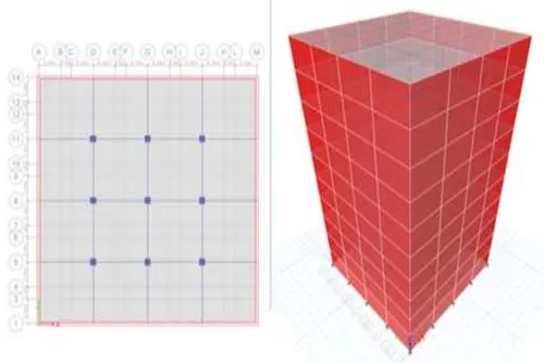
4. Modelling of Structure:
The given frame structure is modelled in four different ways and it is analysed by using E-TABS2015. Response spectrum analysis and equivalent static analysis are carried out for all models.
Model 1: Normal Building with Column beam joint.
Model 2: Building with opening in shear wall.
Model 3: Building with four side shear walls.
Model 4: Building with coupled shear wall
MODEL 1:
Fig.3) Normal Building with Column beam joint
MODEL 2:
Fig.4) Building with opening in shear wall
MODEL 3:
Fig.5) Building with four side shear walls
MODEL 4:
[image:3.612.330.563.93.276.2] [image:3.612.322.572.324.491.2] [image:3.612.59.277.465.655.2] [image:3.612.325.572.539.705.2]© 2018, IRJET | Impact Factor value: 6.171 | ISO 9001:2008 Certified Journal | Page 2419
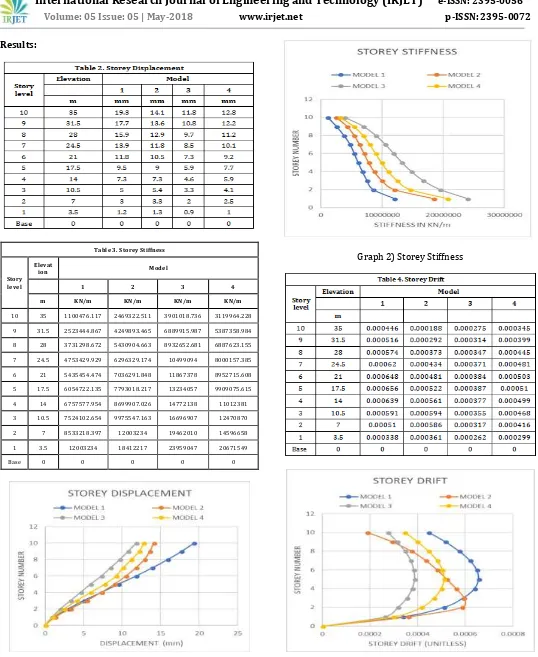
[image:4.612.36.574.43.700.2]Results:
Table 3. Storey Stiffness
Story level
Elevat
ion Model
1 2 3 4
m KN/m KN/m KN/m KN/m
10 35 1100476.117 2469322.511 3901018.736 3119964.228
9 31.5 2523444.867 4249893.465 6889915.987 5387358.984
8 28 3731298.672 5430904.663 8932652.681 6887623.155
7 24.5 4753429.929 6296329.174 10499094 8000157.385
6 21 5435454.474 7036291.848 11867378 8952715.608
5 17.5 6054722.135 7793018.217 13234057 9909075.615
4 14 6757577.954 8699907.026 14772138 11012381
3 10.5 7524102.654 9975547.163 16696907 12470870
2 7 8533218.397 12003234 19462010 14596658
1 3.5 12003234 18412217 23959047 20671549
Base 0 0 0 0 0
Graph 1) Storey Displacement
Graph 2) Storey Stiffness
© 2018, IRJET | Impact Factor value: 6.171 | ISO 9001:2008 Certified Journal | Page 2420
Conclusions
:Coupling beams are designed to take deformations as well as capable of taking shear capacity.
1. The displacement is least for the 3rd and 4th model compared
to other to models.
2. Storey stiffness is more for the 3rd and 4th model compared
to other two models.
3. Storey drift for the 1st model is highest and least for 3rd
model.
From the above graphical comparisons, it is concluded that model with coupled shear wall performance is same as shear wall provided all side and better performance than other two models. So, coupled shear with coupling beams is the potential option in high-rise building when there opening is provided between two shear walls in multistory buildings.
REFERENCES
[1] J. C. D. Hoerderkamp: The Influence of Single Shear Walls on the Behavior of Coupled Shear Walls in High-rise Structures (Vol. 25, No. 3, October 1998).
[2] Harries KA, Moulton JD and Clemson RL
(2004): Parametric study of coupled wall behavior implications for the design of coupling beams. Journal of Structural Engineering, ASCE. 130(3), pp. 480-488
[3] Stafford Smith B, Hoenderkamp J.C.D.3 and Kuster M (1984): Generalized Method for Estimating the Drift in High-Rise Structures. Journal of the Structural Division, ASCE. 110(7), pp. 1549-1562
[4] Subedi and N. K. (1991). "RC coupled shear wall structures Analysis of coupling beams." Structural engineering, ASCE, 117(3), 667-680.
[5] Hassan, M. and El-Tawil: "Inelastic dynamic behavior of hybrid coupled walls", Journal of Structural Engineering, ASCE, 130(2004) 285-296.
[6] Eljadei A: "Performance based design of coupled wall structures". Ph.D. Dissertation. University of Pittsburgh; 2012. 221p.
[7] B. Stafford Smith and D.P.Abergel: “Approximate Analysis Of High Rise Structures Comprising Coupled walls and Shear Walls”, Building and Environment, Vol. 18, pp 91-96, 1983
[8] Chaallal O, Gauthier D and Malenfant P. Classification methodology for coupled shear walls.
Journal of Structural Engineering, ASCE. 122, pp. 1453-1458
[9] Chitty L: On the cantilever composed of a number of parallel beams interconnected by cross-bars. Philosophical Magazine. 38(7).
[10] O.Lavan:Viscously coupled shear walls: Concept, simplifiedanalysis, and a design procedure.
[11] Sammed S. Rangolli and Dr.Vinod Hosur :
Analysis Of Multi-Storey Building By Using Coupled Shear Walls.
[12] Y. H. Chai and Yanfei Chen: Natural Periods of Coupled Shear Walls Via Differential Transformation.
[13] I.S. 1893: Criteria for Earthquake Resistance design of structures-part1, New Delhi (India),2002