White Rose Research Online URL for this paper:
http://eprints.whiterose.ac.uk/97551/
Version: Accepted Version
Article:
Iten, Raban, Colbeck, Roger orcid.org/0000-0003-3591-0576, Kukuljan, Ivan et al. (2 more
authors) (2016) Quantum circuits for isometries. Physical Review A. 032318. ISSN
1094-1622
https://doi.org/10.1103/PhysRevA.93.032318
[email protected] https://eprints.whiterose.ac.uk/ Reuse
Items deposited in White Rose Research Online are protected by copyright, with all rights reserved unless indicated otherwise. They may be downloaded and/or printed for private study, or other acts as permitted by national copyright laws. The publisher or other rights holders may allow further reproduction and re-use of the full text version. This is indicated by the licence information on the White Rose Research Online record for the item.
Takedown
If you consider content in White Rose Research Online to be in breach of UK law, please notify us by
Raban Iten,1 Roger Colbeck,2 Ivan Kukuljan,3 Jonathan Home,4 and Matthias Christandl5 1ETH Z¨urich, 8093 Z¨urich, Switzerland ([email protected])
2Department of Mathematics, University of York, YO10 5DD, UK ([email protected]) 3University of Ljubljana, 1000 Ljubljana, Slovenia
4Institute for Quantum Electronics, ETH Z¨urich, Otto-Stern-Weg 1, 8093 Z¨urich, Switzerland 5Department of Mathematical Sciences, University of Copenhagen,
Universitetsparken 5, 2100 Copenhagen Ø, Denmark (Dated: 15th March 2016)
We consider the decomposition of arbitrary isometries into a sequence of single-qubit and Controlled-not(C-not) gates. In many experimental architectures, the C-not gate is relatively ‘expensive’ and hence we aim to keep the number of these as low as possible. We derive a theoretical lower bound on the number ofC-notgates required to decompose an arbitrary isometry frommto
nqubits, and give three explicit gate decompositions that achieve this bound up to a factor of about two in the leading order. We also perform some bespoke optimizations for certain cases where m
andnare small. In addition, we show how to apply our result for isometries to give a decomposition scheme for an arbitrary quantum operation via Stinespring’s theorem, and derive a lower bound on the number of C-nots in this case too. These results will have an impact on experimental efforts to build a quantum computer, enabling them to go further with the same resources.
I. INTRODUCTION
Quantum computers would allow us to speed up several important computations including search [1, 2], quantum simulation [3] and factoring [4]. The ability to do the latter would render RSA [5], a widespread cryptographic protocol, unfit for purpose. However, constructing a de-vice capable of performing such computations is one of the biggest challenges facing the field, and many candi-date platforms remain in their infancy, operating only with a few qubits at best.
In spite of this, the theory of quantum computation is quite advanced. At an abstract level, a quantum compu-tation corresponds to a unitary operation, and a universal quantum computer should be able to perform arbitrary unitary operations (each to very high precision). Rather than having a different component for each unitary oper-ation, it is convenient to break down such operations in terms of a small family of simple-to-perform gates. This is the aim of the circuit model of quantum computation, which mirrors an analogous model for classical computa-tion, in which an arbitrary computation can be decom-posed in terms of (for example)not,and,orandC-not gates. In the quantum case, several examples of univer-sal gate libraries are known (see for example [6]). In this work we focus on one involving arbitrary single-qubit op-erations andC-notgates. This gate set is universal for quantum computation in the sense that an arbitrary n -qubit unitary can be decomposed in terms of these gates alone [7] and is particularly well-suited to certain archi-tectures in which these operations are relatively straight-forward to implement. Of these operations, C-not is often the most difficult to perform since in all experimen-tal architectures it involves connecting the qubits using an additional degree of freedom [8, 9]. This provides additional channels for the introduction of decoherence. The mediated interaction also typically requires longer
gate times, increasing susceptibility to direct qubit de-coherence. As an example, the current lowest infideli-ties achieved experimentally are<10−6 for single-qubit gates [10] and ∼ 10−3 for two qubit gates [11]. Tak-ing this as our motivation, we use the number ofC-not gates required in a decomposition as a measure of the complexity of a gate sequence and we consider circuits that minimize the number of such gates.
This task has been previously considered both for ar-bitrary unitary operations and for state preparation (see for example [12, 13] and references therein). In [12], a decomposition scheme was found for an arbitrary uni-tary operation onnqubits that requires 23484n C-nots to leading order, approximately twice as many as the best known lower bound [14, 15]. Similarly, in order to pre-pare a state ofnqubits (starting from the state|0i⊗n), the best known construction requires 23
242
n C-nots to
leading order if n is even [13], and 2n to leading order ifn is odd [16], which is again approximately twice the best known lower bound [13].
con-TABLE I: Lowest known upper bounds and highest known lower bounds on the number ofC-notgates required to decompose
mtonisometries for largen. For simplicity, all the counts are depicted to leading order. As is to be expected, the number of requiredC-notgates increases withm(i.e., when fewer of the input qubits start in a fixed state).
m Lower Bound [LB] Upper Bound [UB] UB/LB References for Upper bound
m= 0 (SP) 1
22
n[13] 23
242
n ≃1
.9 [13] (neven), Rmk. 5 (nodd)
16m6n−2 1 22
n+m−4m−1 2n+m− 1 242
n <2.3a Eq. (A21), (Theorem 2)b
m=n−1 3
164
n 23
644
n ≃1
.9 Eq. (A22)
m=n(Unitary) 1 44
n[14, 15] 23
484
n ≃1.9 [12]
aIf 16m6n−5 we have UB/LB.2 (for large enoughn). bIn the case 56m6 n−2 and evenn, Theorem 2 achieves a
slightly lowerC-notcount of 2324(2n+m+ 2n) to leading order.
sider the problem of synthesis of general isometries from
mqubits ton>mqubits.
This task was first considered by Knill [17], whose de-composition scheme is based on a dede-composition scheme for state preparation (and uses such a scheme as a black box). His decomposition scheme together with the state preparation scheme of [16] (or [13]) leads directly (with-out any optimizations) to an decomposition of m to n
isometries requiring about 2·2m+n C-nots to leading order. However, this can be modified (together with the decomposition scheme for state preparation described in [13]) to achieve 2m+n+ 2n to leading order, which is our first decomposition scheme.
We also introduce two others. Our second scheme is a column-by-column decomposition of an isometry that requires about 2m+n C-notgates to leading order. This decomposition also performs well for cases wherem and
nare small. For our final scheme, we adapt the decom-position of arbitrary unitaries [12] to isometries, leading to aC-notcount of about 0.16·(4m+ 2·4n) to leading order.
To compare the quality of our schemes we give a the-oretical lower bound on the number of C-notgates re-quired to decompose arbitrary isometries. These results are summarized in Tables I and II. As shown in Table I, for large enoughn, in the worst case our decomposition scheme uses roughly 2.3 times the number ofC-nots re-quired by the lower bound (the worst-case being ann−2 to n isometry). This is comparable to the factor of 1.9 already known in the special cases of state preparation and of arbitrary unitary operations.
In addition, we optimize the C-not counts for m to
n64 isometries in Appendix B (see Table III for a sum-mary). These are most likely to be of practical relevance for experiments performed in the near future.
TheC-not counts in Table I, Table II and Table III can be directly used to upper bound the total number of gates needed for the decomposition. Since each C-not gate can introduce at most two single-qubit gates into a quantum circuit without redundancy (cf. Section III for
similar arguments1), the number of single-qubit gates required for an isometry can be bounded by doubling the counts given in the two tables and adding n, the number of qubits in question.
Although we have ranked the decompositions in terms of gate counts above, there may be other features of a given decomposition scheme that make it preferable to another which may depend on the physical setup. It is also interesting to note that our decomposition schemes use others in a black box fashion (cf. Section V for more details), e.g., the decomposition scheme of Knill uses a scheme for state preparation as a black box. An im-provement in the decomposition of the black box would therefore directly improve the corresponding decomposi-tion for an isometry, potentially altering the ordering in terms of gate counts.
II. BACKGROUND INFORMATION AND NOTATION
We work in the circuit model of quantum computation in which the fundamental information carriers are qubits. A computational basis state of the 2n-dimensional Hilbert spaceHn =H⊗n
1 of ann qubit register can be written as|bn−1i ⊗ |bn−2i ⊗ · · · ⊗ |b0ior, in short
nota-tion, as |bn−1bn−2. . . b0i, where bi ∈ {0,1}. To abbre-viate further we write|bn−1bn−2. . . b0i=
Pn−1 i=0 bi2i
E
n, i.e., we interpret the bit string bn−1bn−2. . . b0 as a bi-nary number. If n = 1 we omit the subindex. Thus, |1i3=|001i=|0i ⊗ |0i ⊗ |1i, for example.
In the circuit model of quantum computation, informa-tion carried in qubit wires is modified by quantum gates, which correspond mathematically to unitary operations.
1Note that we count arbitrary single-qubit gates here (rather than
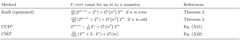
[image:3.595.54.564.97.183.2]TABLE II: Overview of the number ofC-not gates required to decomposem to n isometries using different decomposition schemes (NB: for smallnwe have done some additional optimizations—see Table III). Abbreviations used:aColumn-by-column
decomposition of an isometry;bDecomposition of an isometry using the Cosine-Sine Decomposition.
Method C-notcount for anmtonisometry References
Knill (optimized) 2324(2m+n+ 2n) +O n2
2m ifnis even Theorem 2
115 96(2
m+n+ 2n) +O n2
2m if
nis odd Theorem 2
CCDa 2m+n− 1
242
n+O n2
2m Eq. (A21)
CSDb 23
144(4
m+ 2·4n) +O(
[image:4.595.92.296.420.500.2]m) Eq. (A22)
TABLE III: Smallest known achievableC-not counts form
to 26n64 isometries. The counts forn=mare as in [12]. The counts for state preparation (m= 0) on two and three qubits are taken from [18], and the count for state prepa-ration on four qubits follows from the decomposition scheme described in Appendix A 5. The remaining cases are discussed in Appendix B. Note that theC-notcounts grow very fast. For example, any unitary on 10 qubits can be performed using about 500000C-notgates.
@ @@ n
m
0 1 2 3 4
2 1 2 3 − −
3 3 9 14 20 −
4 8 22 54 73 100
In particular, we will use the following single-qubit gates:
Rx(θ) =
cos[θ/2] −i sin[θ/2] −i sin[θ/2] cos[θ/2]
; (1)
Ry(θ) =
cos[θ/2] −sin[θ/2] sin[θ/2] cos[θ/2]
; (2)
Rz(θ) =
e−iθ/2 0 0 eiθ/2
, (3)
which correspond to rotations by angleθabout thex-,y -and z-axes of the Bloch sphere. One important special case is thenotgate,σx= iRx(π) in terms of which the C-notgate can be written as|0ih0| ⊗I+|1ih1| ⊗σx.
Lemma 1 (ZYZ decomposition) For every unitary operationU acting on a single qubit, there exist real num-bers α, β, γ andδsuch that
U =eiαRz(β)Ry(γ)Rz(δ). (4) A proof of this decomposition can be found in [6]. Note that (by symmetry) Lemma 1 holds for any two ortho-gonal rotation axes. Lemma 1 shows that a single-qubit gate can be specified by three real parameters neglecting the (physically insignificant) global phase eiα. This is analogous to the description of a rotation in 3-dimensions being parameterized in terms of threeEuler angles, here
β,γ andδ.
It is convenient to represent quantum circuits diagram-matically. Each qubit is represented by a wire and gates are shown using a variety of symbols. Conventionally time flows from left to right. We will use the concept of circuit topologies, as in [14, 15], throughout this paper. A general circuit topology corresponds to a set of quantum circuits that have a particular structure, but in which some gates may be free or have free parameters. For ex-ample, Lemma 1 can be expressed as an equivalence of two circuit topologies.
U = Rz Ry Rz
The general meaning of a circuit topology equivalence is the following: for all possible values of the (free) pa-rameters of the circuit topology on the left hand side there exist values for the parameters of the circuit topol-ogy on the right hand side such that the two sides perform the same operation (up to a global phase). For example, each of theRz gates in the above circuit represents a z -rotation gate with unspecified angle. If we use symbols for certain gates that have not been introduced before, they are considered to be arbitrary quantum gates (these will often be denoted byU). If the same symbol is used as a placeholder for more than one quantum gate, we mean that all gates are of this form, but the gates themselves don’t have to be identical (as in the previous example where althoughRz appears twice on the right hand side, each instance can have a different rotation angle).
III. LOWER BOUND
First we derive a theoretical lower bound on the num-ber ofC-notgates required to decompose an isometry. For this purpose we use a similar argument as that used to derive theoretical lower bounds for general quantum gates [14, 15] or for state preparation [13]. Letmandn
be natural numbers withn>2 and m6n. An m ton
isometry can be represented by a 2n×2mcomplex matrix satisfyingV†V =I
2m×2m. Therefore such an isometry is
described by 2n+m+1−22m−1 real parameters, where the −1 accounts for the physically negligible global phase.
state, which we take to be |0i2. Without any C-nots, all we can do is apply single-qubit unitaries individually to each of these nqubits. Each such unitary introduces at most 3 parameters (cf. Lemma 1). However, for the qubits that start in state|0i, only two parameters are in-troduced, since a qubit state is fully specified by two real parameters. In order to introduce further parameters, C-notgates are required.
One might expect each C-not gate to allow the in-troduction of six real parameters by placing arbitrary single-qubit rotations after the control and target. How-ever, since Rz gates commute with control qubits, and
Rx gates with target qubits, we can introduce at most four parameters for each additionalC-notgate [14, 15]. In essence we are using the following circuit identity
• Rz Ry Rz Rz • Ry Rz =
Rx Ry Rx Rx Ry Rx
which implies
U • U U • Ry Rz
=
U U U Ry Rx
(5)
We conclude, that we can introduce at most 3m+2(n−
m) + 4rreal parameters usingr C-notgates.
In order to be a valid circuit topology, i.e., one that can generate everymtonisometry by an appropriate choice of its parameters, the number of parameters introduced into the circuit by the single-qubit rotations must exceed the number of parameters required to specify an arbitrary
mto nisometry. Thus, the number ofC-nots required for such a circuit topology,Niso(m, n), must satisfy 3m+ 2(n−m) + 4Niso(m, n)>2n+m+1−22m−1. From this we obtain the following lower bound
Niso(m, n)> 1 4 2
n+m+1−22m−2n−m−1
. (6)
We remark that we can rephrase our result (by similar arguments as used in [14, 15]) as follows: almost every
mto nisometry cannot be decomposed into a quantum circuit (comprising single-qubit unitaries and C-nots) with fewer than ⌈1
4 2
n+m+1−22m−2n−m−1 ⌉ C-not gates. It is worth saying that the set of measure zero that is excluded from this statement contains sev-eral interesting isometries, for example that required for Shor’s algorithm [4]. This lower bound provides a limita-tion on auniversal quantum computer, rather than one tailored to a specific task.
2 Note that additional ancilla qubits will not affect the lower
bound. This can be seen by using the same arguments that we use in the derivation of the lower bound for quantum channels (see Section VI).
IV. DECOMPOSITION SCHEMES FOR ISOMETRIES
Any isometry, V, from m qubits to n qubits can be described by a 2n ×2m matrix. This can instead be represented by a 2n ×2n unitary matrix, U, by writ-ing V = U I2n×2m, where I2n×2m denotes the first 2m
columns of the 2n×2n identity matrix. Note that U is not unique (unlessm=n). Our aim is to find a decom-position of a quantum gate of the form U in terms of C-nots and single-qubit gates. We describe three con-structive decomposition schemes for arbitrary isometries. This section focuses on the ideas behind these decompo-sition schemes; the full technical details can be found in Appendix A. It is also worth noting that the proof of each of these schemes can be seen as an alternative way to prove the universality of the gate library containing single-qubit andC-notgates [7].
A. Notation for controlled gates
We use l-qubit-Cu
k(U) to denote a gate that performs a different l-qubit unitary for each possible state of k controlqubits, whereUis a placeholder for a size 2kset of 2l-dimensional unitary operations. We call an operation of this type a uniformly controlled gate (UCG). These are also referred to as “multiplexed gates” by some authors, e.g. [12]. Ifl = 1 we abbreviate the notation toCu
k(U). If we writeRx,Ry orRz instead ofU, we mean that all the 2k single-qubit gates that determine the UCG are of the form of the corresponding rotation gate.
In order to write such gates out more precisely, we split the Hilbert space ofnqubits into a 2k-dimensional space corresponding to the control-qubits, a 2l-dimensional space corresponding to the target-qubits and a 2f -dimensional space, where f := (n−l−k), corresponds to the free qubits, i.e., the qubits we neither control nor act on: Hn =Hk⊗ Hl⊗ Hf. If F is anl-qubit-Cu
k(U) gate, then it acts according to
F|i1ik⊗ |i2il⊗ |i3if=|i1ik⊗(Ui1|i2il)⊗ |i3if, (7)
where i1 ∈ {0, . . . ,2k −1}, i2 ∈ {0, . . . ,2l −1}, i3 ∈ {0, . . . ,2f −1} and U
i1 denotes the quantum gate act-ing on the target qubits if the control qubits are in the state|i1ik. If each member of the setUi1 apart from one (call this oneUj) are equal to the identity operation, we drop the word “uniformly” and call such an operation a
k-controlled l-qubit gate, denoted by l-qubit-Ck(Uj), or more generally a multi-controlled gate (MCG). Ifl = 1 and we want to emphasize the total numbernof qubits of the system being considered, we add annas a second subindex, i.e. Ck(U) becomesCk,n(U).
By way of example, the following circuit diagram shows a 2-qubit-Cu
C2,4(U)) gate in this order (from left to right). •
•
U • U
U
Note that theCk(U) notation does not specify which are the control- and which are the target-qubits and whether we control on|1i(filled circle) or on|0i(unfilled circle); these must be made clear in the particular context.
Each uniformly k-controlled gate can be decomposed into a sequence of 2kk-controlled gates, as should be clear from the following example for the casek= 2,l=n−2 andn>3.
• •
= • •
l \ U l \ U0 U1 U2 U3
The symbol “\” stands for a data bus of several (in this casel) qubits. Note that the UCG above has block struc-tureU0⊕U1⊕U2⊕U3.
Remark 1 In Table IV of Appendix A 2 we give an overview of C-not counts for some special controlled gates that are used for decompositions arising in this pa-per.
B. Decomposition of isometries using the decomposition scheme of Knill
In this section we combine the decomposition scheme for isometries of Knill [17] and the state preparation scheme described in [13]. The main result is as follows.
Theorem 2 Letmandnbe natural numbers withn>5
and m6n and V be anm to n isometry. There exists a decomposition of V in terms of single-qubit gates and C-nots such that the number of C-not gates required satisfies3
Niso(m, n)6(2m+ 1)(NU(⌊n/2⌋) +NU(⌈n/2⌉)) +2m+1NSP(⌊n/2⌋) +O n22m, (8)
where NU(n) denotes the number of C-not gates
re-quired for an arbitrary unitary on n qubits. Using the best known C-notcounts for unitaries and state prepa-ration (cf. Table I) this leads to
Niso(m, n)6 23 24(2
m+n+ 2n) +O n2
2mif nis even,
Niso(m, n)6 115
96 (2
m+n+ 2n) +O n2
2m ifn is odd.
3 The exact count for this decomposition can be obtained by
re-placingO(n2) by 16n2−60n+ 42
Remark 2For large n, the last two terms in (8) are negligible. The leading order for this scheme is therefore derived from that of a unitary onn/2qubits.
Consider a set of unitary operations {Vi}2m−1 i=0 such thatVi|0i=V|ii, i.e.,Vi is a unitary for state prepara-tion on the state corresponding to theith column of V. In the proof of Theorem 3.1 of [17] it is shown that
U =V2m−1Cn−1(P(θ2m−1))V2†m−1. . . V0Cn−1(P(θ0))V0†,
(9) where the gateP(θ) :=eiθ|0ih0|+|1ih1|. Consider decom-posing each Vi using the (reverse of the) decomposition scheme for state preparation described in [13]. This leads to a circuit containing 2m−1 instances of the following circuit diagram (shown in the case, wherenis even), each corresponding to a unitary of the formVi+1† Vi.
SP
•
U1 U3 •
SP†
..
. . .. ...
• •
U2 U4 ..
. . .. ...
We can merge the unitaries and define ˜U1:=U3U1and ˜
U2:=U4U2.
SP
•
˜
U1 •
SP†
..
. . .. ...
• •
˜
U2 ..
. . .. ...
We decompose all the terms of the formVi+1† Viin equa-tion (9) in this way. The gateV2m−1 andV†
0 can also be decomposed using the (reversed) decomposition scheme for state preparation described in [13]. TheCn−1(P(θi)) gates are special cases of Cn−1(U) gates. Hence, each can be decomposed into 16n2−60n+ 42 C-not gates (see Lemma 13). This leads to the claimedC-notcount given in equation (8).
C. Column-by-column decomposition
In this section we introduce a circuit topology corre-sponding to a column-by-column decomposition of an ar-bitrary isometry, i.e., we decompose any isometry into single-qubit andC-notgates proceeding one column at a time.
Theorem 3Letmandnbe natural numbers withn>2
ψ00
= ∗ ∗ ∗ ∗ ∗ ∗ ∗ ∗ ∗ ∗ ∗ ∗ ∗ ∗ ∗ ∗
Cu3(U0u,0) −−−−−−→ ∗ 0 ∗ 0 ∗ 0 ∗ 0 ∗ 0 ∗ 0 ∗ 0 ∗ 0
Cu2(U0u,1) −−−−−−→ ∗ 0 0 0 ∗ 0 0 0 ∗ 0 0 0 ∗ 0 0 0
Cu1(U0u,2) −−−−−−→ ∗ 0 0 0 0 0 0 0 ∗ 0 0 0 0 0 0 0
Cu0(U0u,3) −−−−−−→ 1 0 0 0 0 0 0 0 0 0 0 0 0 0 0 0
U0u,3
Uu 0,2
U0u,1
[image:7.595.151.490.57.232.2]U0u,0
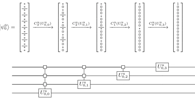
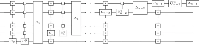
FIG. 1: Implementing the first column of an isometryV fromm>0 qubits ton= 4 qubits. The action ofG0on
ψ00
:=V|0im can be decomposed into operators{Gi0}i∈0,1,2,3, whereGi0 :=C3u−i(U0u,i). The upper part shows how these gates successively
zero the entries of the column, while the lower part gives the circuit representation. The inverse of this decomposition scheme was introduced in [16] for state preparation together with an efficient decomposition of the uniformly controlled gatesGi0 into C-nots and single-qubit gates. The symbol “∗” denotes an arbitrary complex number.
C-nots such that the number of C-not gates required satisfies
Niso(m, n)62m(Σns=0−1N∆Cu
n−1−s) +O n
2
2m,
whereN∆Cu
n−1−s denotes the number of C-notgates
re-quired to decompose a Cu
n−1−s(U) gate up to a
diago-nal gate ∆, i.e., to decompose the two gates together, where the Cu
n−1−s(U) gate is determined but we are free
to choose the diagonal gate ∆. Together with the best known decomposition scheme for UCGs (up to diagonal gates) [16] this leads to
Niso(m, n)62m+n+O n2
2m.
We defer a rigorous proof of the theorem to Ap-pendix A 3, and instead use this section to explain the main ideas behind the argument. Our proof is con-structive, and the exact C-notcount is given in equa-tion (A21).
As before, we represent the m to n isometry V by a 2n ×2n unitary matrix, here G†, by writing V =
G†I
2n×2m. Since a C-not gate is inverse to itself and
the inverse of a qubit unitary is another single-qubit unitary, searching for a decomposition scheme for
G† is equivalent to searching for a decomposition of a
unitary operationGsatisfyingGV =I2n×2m.
In essence, the idea is to find a sequence of unitary operations that when applied toV successively bring it closer toI2n×2m. We will do this in a column by column
fashion, first choosing a sequence of quantum gates, cor-responding to a unitary G0 that gets the first column right, i.e., G0V|0im = I2n×2m|0i
m = |0in, we then use G1 to get the second column right without affect-ing the first, i.e., G1G0V |1im=I2n×2m|1i
m=|1in and
G1G0V|0im=G1|0in=|0in, and so on (up to the 2mth
column). In other words, Gk gets the (k+ 1)th column right and acts trivially on the firstkcolumns ofI2n×2m.
The gateG0 can be decomposed into single-qubit and
C-notgates by reversing a decomposition scheme for the preparation of a state (applied toV|0im). It is natural to imagine repeating this construction for each column in turn. However, without further modification, this pro-cedure doesn’t work since the action required for the decomposition of later columns affects those that have already been done. In other words, if we construct a unitary ˜G1 again by reversing a decomposition scheme for state preparation, we can obtain ˜G1G0V |1im=|1in, but, in general, ˜G1G0V|0im6=|0in. We therefore intro-duce a modified technique that takes this into account while only slightly increasing the number ofC-notgates needed over that required for state preparation on each column. This technique develops an idea used for state preparation using uniformly controlled gates [16].
Lemma 4Let |ψ′i ∈ H1 and define r such that
hψ′|ψ′i=r2. There existU
0, U1∈SU(2), such that
U0|ψ′i = r|0i, (10)
U1|ψ′i = r|1i. (11) Proof. Define |ψi = 1
r|ψ
′i and |φi = − hψ|1i |0i+
hψ|0i |1i ∈ H1. ThenU0=|0ihψ|+|1ihφ|is unitary with detU0= 1 and obeys equation (10). U1 can be obtained analogously.
As noted above, the unitary operation G0 can be de-composed using the reverse of the decomposition scheme for state preparation as described in [16]. First we act with a UCG G00 = Cnu−1(U0,0u ) on the least signif-icant qubit. The gate G0
0 has a 2×2 block diagonal structure. Using Lemma 4 we can construct G0
ψ01
= 0 ∗ ∗ ∗ ∗ ∗ ∗ ∗ ∗ ∗ ∗ ∗ ∗ ∗ ∗ ∗
C3u(U1u,0)
−−−−−−→ 0 ∗ 0 ∗ 0 ∗ 0 ∗ 0 ∗ 0 ∗ 0 ∗ 0 ∗
C2u(U1u,1)
−−−−−−→ 0 ∗ 0 ∗ 0 ∗ 0 0 0 ∗ 0 0 0 ∗ 0 0
C3(U1,1) −−−−−−→ 0 ∗ 0 0 0 ∗ 0 0 0 ∗ 0 0 0 ∗ 0 0
C1u(U1u,2)
−−−−−−→ 0 ∗ 0 0 0 ∗ 0 0 0 ∗ 0 0 0 0 0 0
C3(U1,2) −−−−−−→ 0 ∗ 0 0 0 0 0 0 0 ∗ 0 0 0 0 0 0
C3(U1,3) −−−−−−→ 0 1 0 0 0 0 0 0 0 0 0 0 0 0 0 0
U1,3
U1u,2 U1,2
U1u,1 U1,1
Uu
[image:8.595.91.551.57.231.2]1,0 • • •
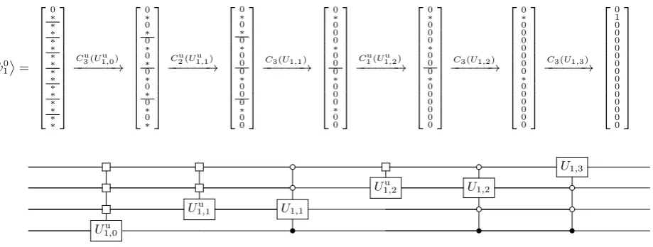
FIG. 2: Implementing the second column of an isometry V from m > 1 qubits to n = 4 qubits. The operation of G1 on
ψ01
:= G0V |1im can be decomposed into operators {G i
1}i∈0,1,2,3, where G01 = C3u(U1u,0), G11 = C3(U1,1)C2u(U1u,1), G21 =
C3(U1,2)C1u(U1u,2) and G31 =C3(U1,3). Note that all these gates act trivially on |0in. The symbol “∗” denotes an arbitrary
complex number.
that it zeroes every second entry of ψ00
:= V |0im (see Fig. 1). This corresponds to disentangling (i.e., rotating to product form) the least significant qubit, so we can write G0
0 ψ00
= ψ10
⊗ |0i for some state
ψ10
∈ Hn−1. Now we apply the same procedure to
ψ10
leaving the least significant qubit invariant. We act withG1
0:=Cnu−2(U0,1u ), which corresponds to condition-ally rotating the second least significant qubit, leading to G1
0G00 ψ00
= ψ02
⊗ |0i ⊗ |0i, for some ψ20
∈ Hn−2. We continue in this fashion until all the qubits have been disentangled. Thus we have constructed a quantum gate
G0:=Gn0−1G n−2
0 . . . G00 such thatG0 ψ00
=|0in4. In the following we describe how to construct a unitary
G1 setting the second column of G0V to (0,1,0, . . . ,0) without affecting the first column. We construct G0
1 =
Cu
n−1(U1,0u ) choosing the unitary operations such that the first entry of each pair becomes zero (see Fig. 2). In other words, defining ψ01
:= G0V|1im we have
G0 1 ψ01
=
ψ11
⊗ |1i, for some state ψ11
. Note that, by construction, the first column ofG0V in matrix form is (1,0, . . . ,0), and, sinceG0is unitary, the first row also has the form (1,0, . . . ,0). Hence the first entry of ψ10
is already 0 and we can set the upper most 2×2 block of the uniformly controlled gateG0
1, i.e. the block acting on the states|0in and|1in, to the identity. Therefore we can perform this step without affecting the first column, i.e. G01G0V |0im=G01|0in =|0in. The next step would be to do the same to
ψ11
(i.e., zero every second en-try). Doing so using aCu
n−2(U) gate would, in general, have a non-trivial effect on the basis state |0in.
There-4 Note thatG†
0 is a circuit for preparing the state
ψ00
; in this sense we have performed the inverse of state preparation.
fore we modify the procedure and instead use aCu n−2(U) gate to zero every second entry except that in the up-per most double block of ψ11
or equivalently that in the upper most block of four elements ofG0
1 ψ10
. We subsequently correct for this using an additional MCG acting on the second least significant qubit, i.e., we set
G11=Cn−1(U1,1)Cnu−2(U1,1u ). With this additional MCG we can directly address the quantum states correspond-ing to the two non zero entries in the upper-most four-element block. Indeed, controlling on|0i ⊗ |0i ⊗ · · · ⊗ |0i on the first (n−2) qubits and on|1ion the least signifi-cant qubit we can zero the second non zero entry of the upper-most four-element block without affecting|0in.
We conclude that G1 1G01
ψ01
=
ψ21
⊗ |0i ⊗ |1i and
G1
1|0in = |0in. We continue in this way, until the most significant qubit is disentangled. We have there-fore constructed a operationG1such thatG1G0V |1im=
G1 ψ10
=|1in andG1G0V|0im=G1|0in=|0in. This procedure can be continued in a similar fashion, leading to unitariesGksuch thatGkGk−1. . . G0V |kim= |kinandGk|ii=|iifor alli∈ {0,1, . . . , k−1}. For a gen-eral description of the construction of the unitaryGk see Appendix A 3. We can hence construct a unitary opera-torG:=G2m−1G2m−2. . . G0 satisfyingGV =I2n×2m.
In order to compute the number of C-nots used for such a decomposition, we use the following existing re-sults:
(i) N∆Cu
k = 2
k−1C-nots are sufficient to decompose
a UCG withkcontrols, up to a diagonal gate [16].
(ii) N∆(m) = 2m− 2 C-nots are sufficient to de-compose a diagonal gate acting non trivially onm
qubits [19].
Corollary 7.10].
To take advantage of (i), we require a small modifica-tion to our decomposimodifica-tion scheme. Note that instead of implementing the UCGs, we do so up to diagonal gates, i.e., for every k, instead of Cu
k(U) we implement ∆k+1Cku(U), for some diagonal gate ∆k+1onk+1 qubits. The effect of these diagonal gates is then be corrected for at the end of the entire circuit by adding a diagonal gate that acts non-trivially on m qubits and whose C-not count is given in (ii). (In fact, the number ofC-nots re-quired for this is of sufficiently low-order that it doesn’t feature in the count of Theorem 3.)
Furthermore, as shown in Lemma 4, we only require MCGsCn−1(W) forW ∈SU(2), and hence can use (iii). In fact, we have modified the decomposition described in [7] and used some technical tricks (see Appendix A 1) to obtain aC-notcount for aCn−1(W) gate with leading order 28n.
We conclude that we can decompose
each column of an isometry using at most
Ncol = Pns=0−1
N∆Cu
n−1−s+NCn−1(W)
=
Pn−1
s=0 2n−1−s−1
+O(n)
= 2n + O n2
C-nots. Note that (for simplicity) we have overcounted the number of additional MCGs, since in the above we have assumed each Gs
k requires an additional MCG. Therefore, to decompose anmtonisometry, we require at most 2mN
col+N∆(m) = 2m 2n+O n2+ 2m = 2m+n+O n2
2mC-nots.
Note that we implement every column of the isome-try in a similar fashion. However, there are a lot of constraints on the last few columns due to orthogonal-ity, or, in other words, the first k entries of ψ0k
:=
Gk−1Gk−2. . . G0V|kimare already zero by construction and so we have only to act on the other 2n−k entries. Therefore one might expect that the C-not count for
Gk decreases when k increases. Since we use 2n
C-nots to leading order for each column, our decompo-sition scheme doesn’t take an advantage of this fact (for large n). Hence the column-by-column decomposition has some inefficiency in the case wherem≃n(by com-parison to the casem≪n). To give an improved count in the casesm =n−1 and m=n, we introduce a fur-ther decomposition scheme based on the CSD, which is adjusted to the unitary structure, in Section IV D. Note that this scheme corresponds exactly to the decomposi-tion scheme of [12] in the casem=n.
Remark 3 In some physical realizations it is difficult to implement C-not gates between non-adjacent qubits. The decomposition in this section can be adapted to the gate library containing only nearest neighbourC-notand single-qubit gates in a relatively efficient way. To do so, note that the UCGs used to implement one column of an m to n isometry can be performed with at most
(5/3)2n +O n2
nearest neighbour C-not gates [16]. Furthermore, since aC-notgate acting between qubits a distance n apart can be decomposed using O(n) nearest
neighbour C-not gates [12], the MCGs used to imple-ment one column use O n3
nearest neighbour C-not gates. Therefore the decomposition of anm ton isome-try uses at most(5/3)2m+n+O n3
2mnearest neighbour
C-notgates.
D. Decomposition of isometries using the Cosine-Sine Decomposition
The most efficient known decomposition scheme for ar-bitrary unitary operators in term of the number ofC-not gates required uses the CSD [12]. In this section we adapt the decomposition scheme used in [12] tomton isome-tries. To simplify the exposition, the count given here is not the lowest we can obtain; an improvement is given in Appendix 23.
Theorem 5Let m and n be natural numbers with2 6
m6n andV be an isometry from m qubits tonqubits. There exists a decomposition ofV in terms of single-qubit gates andC-nots such that the number ofC-not gates required satisfies
Niso(m, n)63·22n−3−2n+ 2m−4(3·2m−8). (12) The Cosine-Sine Decomposition (CSD) [20] was first used by [21] in the context of quantum computation. In particular, the CSD states that every unitary matrix
U ∈ C2n×2n can be decomposed in terms of unitaries
A0, A1, B0, B1 ∈C2
n−1×2n−1
and real diagonal matrices
CandS satisfyingC2+S2=I:
U =
A0 0 0 A1
C −S
S C
B0 0 0 B1
(13)
The CSD can be summarized by the gate identity
Un
Ry =
n−1 \ \ Un−1 Un−1
Together with
Rz =
n−1 \ Un−1 \ Un−1 Un−1
(14)
(which is Theorem 12 of [12]) it allows a recursive de-composition of an arbitrary unitary operation in terms of single-qubit gates and uniformly controlledRy andRz gates.
In the case of an isometry, we again use a repre-sentation in terms of a unitary matrix, Vn, such that
V =VnI2n×2m. Now, if n > m, we can take the control
qubit of the first (n−1)-qubit-Cu
1(Un−1) gate to be in the state|0i, and hence this gate need not be uniformly controlled. Thus, the following circuit identity holds
|0i
Vn
|0i Ry
=
Note that Vn−1 represents an m to n−1 isometry. In the matrix representation the circuit identity above corresponds to setting B1 = B0 in equation (13). We can decompose the (n−1)-qubit-Cu
1(U) gate as above so that
|0i
Vn
|0i Ry Rz
=
n−1 \ \ Vn−1 Un−1 Un−1
We can use this idea to recursively decomposeVn. The uniformly (n−1)-controlled rotations can be decomposed using at most 2n−1C-notgates [19, 22]. The twoU
n−1 gates can be decomposed by using the CSD and the cir-cuit equivalence (14) recursively until two-qubit gates remain5 (each of which can be implemented with 3
C-nots). In this way it can be shown that each Un−1 re-quires at most (9/16)4n−1−(3/2)2n−1C-notgates [12]. Note that this is not the optimal count reached in [12], but we use this slightly weaker count here for simplic-ity (a count that takes into account the additional opti-mizations of the Appendix of [12] can be found in Ap-pendix A 4). TheC-notcount for an mto n isometry,
Niso(m, n), hence satisfies the recursion relations
Niso(m, i+ 1) =Niso(m, i) +9 84
i−2i, ifm6i < n ,
(15)
Niso(m, m) = 9 164
m−3 22
m. (16)
Solving these leads to the claimed count.
Remark 4 (CSD approach zeroes too many entries)
Recall that constructing a gate Vn such that
V = VnI2n×2m is equivalent to constructing a gate
V†
n such that Vn†V =I2n×2m. Therefore, rewriting
equa-tion (13), the first recursion step of the CSD approach leads to
C S
−S C
A†0 0 0 A†1
U =
B0 0 0 B1
(17)
Ifm < n−1we apply the same procedure toB0.
How-ever, in this case, we already zeroed more entries than necessary in the first recursion step. Specifically, it was unnecessary to zero at least half of the entries in the up-per right and in the lower left 2n−1×2n−1-dimensional
block of the matrix on the rhs of equation (17), and the number of unnecessary zeros grows asmdecreases. This intuitively explains why the CSD approach is not well-suited to m ton isometries, wherem < n−1: by zero-ing too many entries, more C-not gates are used than needed.
5 We could finish the recursion at any stage, such that only ˜n
-qubit unitaries reamain. Therefore, an improvement of the C-notcount for ˜n-qubit unitaries could help to improve theC-not
count given in equation (12) (and equation (A22)).
Remark 5 (Optimized state preparation) As a by-product of the above we obtain an improved bound over that of [16] on the number of C-not gates required for state preparation on an odd number n = 2k+ 1 > 5
of qubits. The optimized decomposition is based on [13] and described in Section A 5. The count (A30) using state preparation onk qubits, which requires 2k−k−1
C-nots (as in [16]), gives the following count for state preparation starting from the basis state|0i⊗n:
NSPopt(n)6 23 242
n−3 22
n+1
2 + 4/3. (18)
Previously, the bound of 23 242
n C-nots to leading
or-der was only known to be achievable for an even number of qubits [13] with a slightly weaker bound of2n C-nots to leading order in the odd case [16]. It is interesting to note the parallelizability of our circuit for state prepa-ration, similarly to [13]. The form of the circuit means that, for large (odd) n, the circuit depth (i.e., the num-ber of computational steps needed to perform the circuit) is about 3/4 of the total gate count. Measuring the cir-cuit depth only in terms of C-nots, our decomposition scheme has depth 23322n to leading order, improving the
previous best known bound of 23 242
n [13]. In the case of
evenn, the minimum known circuit depth is 23482n [13].
V. COMPARISON OF DECOMPOSITIONS
We introduced three constructive decomposition schemes for arbitrary isometries frommtonqubits and derived a lower bound on the number of C-not gates required for such decompositions. The asymptotic re-sults are summarized in Tables I and II. To compare the three decomposition schemes, we consider the ra-tioscK(m, n), cCC(m, n) and cCSD(m, n) of theC-not count for the optimized decomposition scheme of Knill, the column-by-column approach or the CSD approach, respectively, to that of the lower bound for an m to
n isometry. First note that for m > 5 and for large enough n the optimized decomposition scheme of Knill performs similarly to the column-by-column decomposi-tion (i.e., cK(m, n) ≃cCC(m, n)). For m 6 4 we have
cCC(m, n)≃2 andcK(m, n) varies betweencK(4, n)≃2 (ifnis even) andcK(0, n)≃4.8 (ifnis odd). Hence the column-by-column decomposition requires fewerC-not gates if m64 (and nis large). In the case m≃n, the CSD approach may outperform the other two decompo-sitions. For any natural number d and for sufficiently largen, we havecCC(n−d, n) = 2d+2/(2d+1−1) (and
cCC(n−d, n) ≃ cK(n−d, n)) and cCSD(n−d, d) = 23(22d+1+1)
36(2d+1−1). In particular cCC(n − 2, n) ≃ 2.3 and
cCC(n−1, n)≃2.7 for largen. Form=n−1 we can use the CSD approach to again reach cCSD(n−1, n)≃1.9 for largen.
step by step description of how to decomposemton64 isometries in Appendix B. The results are summarized in Table III.
In addition we could use the CSD-approach (and a technical trick) to lower theC-notcount for state prepa-ration. In particular we could lower the lowest known C-notcount for state preparation on 4 qubits from 9 [13] to 8C-nots and on 5 qubits from 26 [13, 16] to 19C-nots (cf. Appendix A 5).
The column-by-column decomposition performs simi-larly to the optimized decomposition of Knill with re-spect to the C-not count, but there are other differ-ences that should be noted. For example, the column-by-column decomposition adapts quite well to implementa-tions where we only allow nearest neighbourC-notgates (cf. Remark 3). The optimized decomposition scheme of Knill has the advantage that some of the gates can be performed in parallel (cf. the circuit diagrams in Sec-tion IV B).
Another important difference between the column-by-column decomposition and the optimized decomposition of Knill is their dependence on the efficiency of the de-composition of their building blocks. In the first case, any improvement of the leading order of theC-notcount of uniformly controlled gates (up to diagonal gates) leads to an improvement of the leading order of the C-not count for isometries (cf. Theorem 3). Where in the sec-ond case, the leading order of theC-notcount depends on the leading order of the C-not count for arbitrary unitary gates (cf. Theorem 2).
Remark 6 Another interesting black box relation can be extracted from [23], where the Sinkhorn normal form for unitary matrices is used to decompose a unitary into a sequence of diagonal gates and discrete Fourier trans-forms (cf. Corollary 1 of [23]). Since we can perform the discrete Fourier transform with a polynomial number of gates, they do not contribute to the leading order of the C-not count of this decomposition. Therefore, this de-composition allows us to relate the efficiency with which we can decompose a unitary with the decomposition of diagonal gates.
VI. APPLICATION TO QUANTUM OPERATIONS
Experimental groups strive to demonstrate their abil-ity to control a small number of qubits, and the ultimate demonstration would be the ability to do any quantum operation on them (i.e., any completely positive trace-preserving (CPTP) map). Since any such operation can be implemented via an isometry followed by partial trace (using Stinespring’s theorem), we can use our decompo-sition scheme for isometries to efficiently synthesize arbi-trary CPTP maps.
Indeed, we can use a similar parameter counting ar-gument as used to derive the lower bound for isome-tries to find a lower bound on the number of C-not
gates required to implement arbitrary CPTP maps via a fixed quantum circuit topology. First we use the Choi-Jamiolkowski isomorphism [24–26] to simplify the param-eter count. This isomorphism states that the set of all CPTP maps from a system Aconsisting ofm qubits to a system B consisting of n qubits is isomorphic to the set of all density operators ρAB on HA⊗ HB satisfying trB(ρAB) = 21mIA. Since a density operatorρAB is Her-mitian, it can be described by 22(n+m) real parameters. The condition trB(ρAB) = 21mIAcorresponds to 22m con-straints, and hence the determination of a CPTP map requires 22(n+m)−22mreal parameters.
We restrict our analysis of the lower bound to the following setting: For the implementation of a CPTP map E from an m-qubit system A to an n-qubit sys-tem B we allow the use of an arbitrary number k of qubits on which we can performC-notand single-qubit gates, before we trace out a systemCconsisting ofk−n
qubits. (Since tracing out qubits commutes with quan-tum gates on the other qubits, without loss of general-ity, we can defer tracing out to the end of the circuit.) We then use a similar argument as used to derive the lower bound for isometries, but instead of commuting theRxandRz gates to the left of eachC-not, we com-mute them to the right so that we perform arbitrary single-qubit unitaries on all of the qubits at the end of the circuit (reversing the order of circuit diagram (5)). Since we have unitary freedom on the system C (be-cause trC((IB ⊗UC)ρBC(IB ⊗UC†)) = trC(ρBC)), the single-qubit gates on each qubit of the systemC at the end of the circuit cannot introduce additional parame-ters. Hence, usingr C-nots, we can introduce at most 4r+ 3n real parameters. By the parameter count for a CPTP map given above, we conclude that a circuit topology has to consist of at least ⌈144m(4n−1)− 3
4n⌉
C-nots in order that it can implement arbitrary CPTP maps frommtonqubits6.
By Stinespring’s theorem, every CPTP mapE from an
m-qubit system A to an n-qubit system B can be im-plemented with an isometryV from systemAto system
BC, where the system C consists of (at most) n+m
qubits, followed by partial trace onC. We can use the column-by-column approach7 to decompose the isome-tryV, which requires 4m+n− 1
242
2n+mC-nots to lead-ing order (without exploitlead-ing the unitary freedom onC). Therefore we have found a way to implement an arbitrary quantum channel from m to n qubits in a constructive and exact way using about four times the number of C-nots required by the lower bound (for large enoughn).
Note that the results of this section are derived in the setting where the CPTP map is implemented in the
quan-6For a more rigorous proof one could use a similar argument as
given in [14, 15].
7The optimized decomposition scheme of Knill also leads to a
tum circuit model. However, this is not the only possibil-ity. For example, alternative methods for the implemen-tation of quantum channels are described in [27] and [28], which allow for additional classical randomness. In fu-ture work we will investigate how to use our approach in an alternative model that allows either measurements or classical randomness as additional resources, in order to further improve theC-notcounts.
Note also that, by Naimark’s theorem, any POVM on a systemA can be implemented using an isometry from systemAto an enlarged system ABfollowed by a mea-surement on system B. Therefore our decomposition schemes for isometries can also be used for the imple-mentation of arbitrary POVMs.
VII. ACKNOWLEDGEMENTS
Part of this work was carried out while MC and RC were with ETH Z¨urich. MC was supported by a Sapere Aude grant of the Danish Council for Indepen-dent Research, an ERC Starting Grant, the CHIST-ERA project “CQC”, an SNSF Professorship, the Swiss NCCR “QSIT” and the Swiss SBFI in relation to COST action MP1006. JH was also supported by the Swiss NCCR “QSIT”. RC acknowledges support from the EPSRC’s Quantum Communications Hub.
We thank Vadym Kliuchnikov for kindly pointing out reference [17].
The authors are grateful to the authors of quant-ph/0406003, whose package Qcircuit.tex was used to produce the circuit diagrams.
Appendix A: Technical details
In this section we give a rigorous proof that the column-by-column decomposition works for arbitrary m
to n isometries and we give an explicitC-notcount in the case n > 8. Since MCG arise in the column-by-column decomposition, we first optimize the decomposi-tion of such gates, based on the decomposidecomposi-tion scheme of [7]. In addition we perform some optimizations for the CSD-approach (based on the Appendix of [12]) and for state preparation.
1. Decomposition of MCGs
In this section we describe how to efficiently decompose MCGsCn−1,n(U), where we focus on the special case of
Cn−1,n(W) gates, whereW ∈SU(2). The decomposition schemes are based on those in [7], except that we use some technical tricks to reduce the number ofC-nots needed. Note that the number of C-nots required is the same whether we control on one or zero, because we can always transform a gate controlled on |0i on a certain control-qubit of a MCG into a gate controlled on|1i using two
σx gates, as illustrated below.
• •
= σx • σx
U U
We denote ak-controllednotgate acting onnqubits byCk,n(σx). In the casek= 2 with control on |1i ⊗ |1i, we call such a gate a Toffoli gate.
Lemma 6 (C1,2(U) gates [7, Corollary 5.3])Any
C1,2(U)gate can be decomposed using two C-notgates,
three special unitary gates A, B and C and a diagonal gate of the formE=|0ih0|+eiδ|1ih1|, where δ∈R.
• E • •
=
U C B A
Lemma 7 (C2,3(U) gates [7, Lemma 6.1]) Any
C2,3(U)gate can be decomposed as follows
• • • •
• = • •
U V V† V
whereV2=U.
Lemma 8 (Toffoli gates [7, Section VI A])A Tof-foli gate can be performed with 6C-nots using the fol-lowing circuit
• • • • E
E • E† •
C B B† B A
where A = Rz(−π2)Ry(π4), B = Ry(−π4), C = Rz(π2)
andE=|0ih0|+ei4π|1ih1|.
Remark 7 ([7, Corollary 6.2]) By adjustingA,B,C and E, the circuit topology in Lemma 8 can be used to generateC2,3(U) for any unitaryU.
Proof. This circuit equivalence follows from Lemma 6 and Lemma 7 together with the following circuit identi-ties.
• • •
• • =
• • •
• = •
Lemma 9 ([7, Section VI B]) Let A :=Ry π4. We
can decompose a Toffoli gate up to a diagonal gate with the following decomposition
•
∆ ∆
• • •
• = • = •
A† A† A A
Proof. To see this, note that if the second control-qubit is in the state |0i, the least significant qubit is unchanged, since AA† =I. If the second control-qubit
is in the state|1iand the first control-qubit in the state |0i, the action on the least significant qubit isA2σ
xA† 2
, which is −|0ih0|+|1ih1|. If both control-qubits are in the state |1i, the action on the least significant qubit is
AσxAσxA†σxA† = σx. We choose the diagonal gate ∆ such that|010iis mapped to − |010i.
Lemma 10 (Diagonal gates commute with UCGs)
k \ ∆ \ ∆
=
l \ U \ U
Proof. By inspection.
Lemma 11 (Ck,n(σx), k6⌈n2⌉) Let n > 5 denote the
total number of qubits considered and k ∈ {1, . . . ,⌈n2⌉}, then we can implement aCk,n(σx)gate with at most(8k− 6) C-nots.
Note that the casek= 1 is trivial and the casek= 2 is implied by Lemma 8 (although we know of a tighter bound in both cases).
To illustrate the idea in the remaining cases, consider the decomposition leading to the desired C-not count fork= 4, n= 7. Lemma 7.2 of [7] shows that
action part reset part
• • •
• • •
• • • • •
• = • •
• • • •
• •
However, we consider instead the alternative decom-position
action part reset part
• •
∆1 ∆1
•
• • •
• •
∆0
•
∆2 ∆2 •
∆0 •
• = • •
• • • •
• •
To see that this is also valid, note that the diagonal gates ∆i are of the same kind as introduced in Lemma 9 and therefore ∆i= ∆†i. By Lemma 10 the two ∆2and ∆1 gates cancel each other out. In addition, the combination of all gates between the two ∆0gates together correspond to a UCG acting only on the least significant (lowest) qubit, and hence the two ∆0 gates cancel out each other by Lemma 10.
The Toffoli gates that don’t act on the least signifi-cant qubit, can be decomposed together with the diag-onal gates using Lemma 9. This leads to the following decomposition of the action part of the last circuit
•
∆1 •
• • • •
• •
• •
• A† A† A A A† A† A A •
whereA =Ry(π4). The marked gates cancel each other out, because they commute with the gates between them. The reset part can be decomposed analogously.
Proof of Lemma 11. First we apply Lemma 7.2 of [7] (a circuit diagram for the case k= 5 and n= 9 can be found in [7]). By similar arguments as used in the special case above, we introduce a corresponding diagonal gate for each Toffoli gate apart from the two that act on the least significant qubit (i.e., on the target qubit of the
Ck,n(σx) gate).
The requiredC-notcount forCk,n(σx) is thus equal to twice that required for the reset part plus the number of C-nots needed to implement the Toffoli gates that form the first and last gate in the action part. By Lemma 8, the two Toffoli gates can be decomposed using 12 C-nots. One reset part usesNreset
Ck,n(σx)= 4(k−3) + 3
C-nots. This leads to the claimed count.
Lemma 12 (Ck,n(σx)[7, Lemma 7.3]) Let n>5
de-note the total number of qubits considered. ACn−2,n(σx)
gate can be decomposed into two Ck,n(σx) and two
Cn−k−1,n(σx) gates, wherek∈ {2,3, . . . , n−3}.
For example, the decomposition for n= 7 and k = 4 is shown in the following circuit diagram.
• • •
• • •
• • •
• = • •
• • •
• •
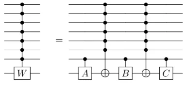
Theorem 13 (Cn−1,n(U))Let n>3 andU be a
single-qubit unitary. We can decompose aCn−1,n(U)gate using
TABLE IV:C-notcounts and numbers of real parameters that can be introduced into a circuit by a specific gate, for various controlled gates.
Gate Notation C-notcount (upper bound) # Real parameters
UCG (up to a diagonal gate) ∆Cnu−1(U) 2n−1−1 [16] 2n
Uniformly controlled rotation Cnu−1(Rz)/Cnu−1(Ry) 2n−1 [19, 22] 2n−1 Multi controlled unitary gate Cn−1,n(U) 16n2−60n+ 42 ifn>3 (Thm. 13) 4
Multi controlled special unitary gate Cn−1,n(W) 28n−88 ifn>8 is even (Thm. 14) 3
(W ∈SU(2)) 28n−92 ifn>8 is odd (Thm. 14) Multi controlled Toffoli gate Ck,n(σx) 8k−6 ifn>5,k∈ {3, . . . ,⌈n
2⌉}(Lemma 11) 0
Proof. The idea is contained in the following diagram in which V is chosen such thatV2=U (see Lemma 7.5 of [7]).
n−2 \ • \ • • •
• = • •
U V V† V
Using Lemma 6, this gives the relation NCn−1,n(U) =
NCn−2,n(U)+ 4 + 2NCn−2,n(σx). For simplicity, we
con-sider the Cn−2,n(U) gate as a Cn−2,n−1(U) gate. This will lead to an overcount in our finalC-notcount. Us-ing Lemma 12 we haveNCn−2,n(σx)= 2(NC⌈n/2⌉−1,n(σx)+
NC⌊n/2⌋,n(σx)) for n > 5 and hence, from Lemma 11,
NCn−2,n(σx)≤16n−40 forn>5. Note that Lemma 8
im-plies that the same bound also holds forn= 4 (although we know of a tighter bound in this case). Thus, we wish to solve the recursionNCn−1,n(U)=NCn−2,n−1(U)+ 32n− 76. Noting that NC2,3(U) = 6 (cf. Remark 7) we obtain the stated count.
Note that this count could be improved. However, it turns out that the caseW ∈SU(2) is particularly useful. In this case we make more effort with the optimizations leading to the following.
Theorem 14 (Cn−1,n(W), where W ∈SU(2)) Let
n>8andW ∈SU(2). We can decompose aCn−1,n(W)
gate using at most (28n−88)C-nots if n is even and (28n−92)C-nots ifnis odd.
Proof. To aid the proof, we provide illustrations for the case n = 8. By Lemma 7.9 of [7] there exist quantum gates A, B, C ∈SU(2) such that we can decompose the
Cn−1,n(W) gate as follows.
• • •
• • •
• • •
• • •
• = • •
• • •
• • • •
W A B C
By Lemma 12 we can decompose theCn−2,n(σx) gates using two Ck1,n(σx) and twoCk2,n(σx) gates, where we
set k2 = ⌈n/2⌉ and k1 = n−k2−1. In our example
k1= 4 andk2= 3:
• • • •
• • • •
• • • •
• • • •
• • • •
• • • •
• • • • • • •
A B C
Since the Cn−2,n(σx) gate is its own inverse, we can use the inverted decomposition scheme to decompose the second Cn−2,n(σx) gate. We can decompose the gates
Ck1,n(σx) and Ck2,n(σx) using Lemma 11. Note that this works for all n> 8, since 36 k1, k2 6⌈n/2⌉. We can lower the C-not count with some technical tricks. As in the proof of Corollary 7.4 of [7] we can decom-pose all Toffoli gates not acting on the least significant qubit up to diagonal gates. This can be seen by re-versing the decomposition scheme of Lemma 11 for the second and fourthCk1,n(σx) gate and using Lemma 10. Therefore, using the same technique as in Lemma 11, but implementing all Toffoli gates up to diagonal gates, we can decompose each of the Ck1,n(σx) gates using
NCk1,n(σx)−2·6 + 2·2 = 8k1−14C-nots.
Now consider the marked part of the last circuit. By Lemma 11 this can be decomposed using
• • • • • • • •
• • • •
• • • •
• • • •
• • • • • • • •
• • • • •
B
where, to simplify, we have not explicitly illustrated the diagonal gates. The two reset parts commute with the controlledB gate, since they don’t act on the two least significant qubits, and cancel out. Therefore each of the marked Ck2,n(σx) gates uses NCk2,n(σx)−N
reset Ck2,n(σx) =
|ψei= 0 .. . 0
cak s
cak
s+1
cak
s+2
cak
s+3
cak
s+4
cak
s+5
.. .
c2n−s−2
c2n−s−1
A −−−→ ψ ′e = 0 .. . 0
c′ak
s+1
0
c′ak
s+1+1
0
c′
ak
s+1+2
0 .. .
c′2n−(s+1)−1 0
, |ψei= 0 .. . 0 0
cak s
cak
s+1
cak
s+2
cak
s+3
cak
s+4
.. .
c2n−s−2
c2n−s−1
A −−−→ ψ ′e = 0 .. . 0 0 c′ ak s+1 0 c′ ak
s+1+1
0
c′ak
s+1+2
.. . 0
c′
[image:15.595.96.526.60.218.2]2n−(s+1)−1
FIG. 3: Using a quantum gateAto disentangle the (n−s)th qubit into the stateks= 0 orks= 1 respectively.
2. Overview ofC-not counts for controlled gates
We summarizeC-notcounts for some commonly-used uniformly and not uniformly controlled gates in Table IV. Note that implementing a uniformly controlledCu
n−1(U) gate up to a diagonal gate ∆ means that we implement ∆Cnu−1(U), for some diagonal gate ∆. The number of real parameters required to specify a particular gate is shown in the final column and follows from Lemma 1 and the block diagonal form of the uniformly controlled gates (see also the argument used to derive the lower bound for isometries in Section III). For example, aCu
n−1(U) gate is described by 2n−1 (2×2)-unitaries. By Lemma 1 this corresponds to 4·2n−1real parameters. Since a diagonal gate ∆ onnqubits is described by 2n real parameters, a ∆Cu
n−1(U) gate is described by 4·2n−1−2n = 2n real parameters.
3. Rigorous proof of the decomposition scheme described in Section IV C and exactC-notcount
We begin this section by introducing some additional notation. Form′ ∈Nandk∈ {0,1, . . . ,2m′ −1} we use the notation: k = [km′−1, km′−2, . . . , k0] :=Pm
′−1
i=0 ki2i, i.e.,{ki}are the binary digits of k. Fors∈N0 we define
aks, bks ∈N0 by k=aks2s+bks, such that aks is maximal. Fors∈ {1,2, . . . , n′−1}, where n′ ∈N
>2 and n′ >m′, we can also write ak
s = [kn′−1, kn′−2, . . . , ks] and bks =
[ks−1, ks−2, . . . , k0].
We now consider an elementary step in the decom-position scheme. Let n ∈ N>2, m ∈ N with n > m,
k∈ {1,2, . . . ,2n−1}ands∈ {0,1, . . . , n−2}. Further-more suppose|ψiis ann-qubit state of the form
|ψi=
2n−s−1
X
l=ak s
cl|li
⊗ |ks−1ks−2. . . k0i, (A1)
wherecl∈Cfor alll∈ {aks, aks+ 1, . . . ,2n−s−1}. Since
it is clear from the context that, e.g., |li ∈ Hn−s, we shorten the notation and write|liinstead of|lin−s.
[Note that we use the following convention: Ifs−1<0, we mean that the part|ks−1ks−2. . . k0iin equation (A1) does not exist, i.e., for s = 0 the statement of equa-tion (A1) is: |ψi=P2n−1
l=ak
0 cl|li. Analogously,I
⊗0means that no such part exists in the considered expression. Similarly we set{ns, . . . , ne}=∅ ifne< ns.]
Lemma 15 Take |ψei := P2n−s−1 l=ak
s cl|li, where “e”
stands for entangled and assume that
c2ak
s+1+1= 0if ks= 0 andb
k
s+16= 0. (A2)
There exists a UCG A:=Cu
n−1−s(U)of the form
A=
2n−1−s−1 X
l=0
|lihl| ⊗Ul⊗I⊗s, (A3)
such that|ψ′i:=A|ψihas the form
|ψ′i=
2n−(s+1)−1
X
l=ak
s+1
c′l|li
⊗ |ksks−1. . . k0i, (A4)
wherec′
l∈Cfor alll∈ {aks+1, as+1k +1, . . . ,2n−(s+1)−1}.
Additionally,Ahas the property that
A|ii=|ii for alli∈ {0,1, . . . , k−1}. (A5)
Proof. The following proof depends on whetherks= 0 orks= 1. In the caseks= 0 we has also to distinguish between the cases bk
s+1 = 0 and bks+1 6= 0. The reader might find it useful to read the proof first considering only the caseks= 1 (and thereforebks+16= 0).
Considering blocks of two elements, there exist two pos-sible forms of |ψei, depending on whether k
s = 0 or