Systems Level Validation of a Distributed
Frequency Control Algorithm
Tung-Lam Nguyen
∗, Efren Guillo-Sansano
†, Mazheruddin H. Syed
†, Steven M. Blair
†, Luis Reguera
†,
Quoc-Tuan Tran
‡, Raphael Caire
∗, Graeme M. Burt
†, Catalin Gavriluta
§, Van-Hoa Nguyen
∗∗University Grenoble Alpes, G2Elab, F-38000 Grenoble, France
†University of Strathclyde, Glasgow, Scotland, UK ‡CEA-INES, Le Bourget-du-lac, France
§AIT Austrian Institute of Technology, Austria
[email protected], [email protected], [email protected]
Abstract—Distributed control and optimization strategies in power systems are gaining more and more attention, especially with the increasing penetration and integration of distributed generation. These novel distributed control and optimization algorithms need to be rigorously validated before their wide-scale deployment and acceptance. In this paper, a testing rig comprising real-time simulation with control and power hard-ware in the loop capability, with a multi-agent system platform and realistic communications emulation is utilized for the systems level validation of a distributed frequency control algorithm. The distributed frequency control is implemented within an islanded microgrid and its performance under two disturbances is assessed under real-world conditions.
Index Terms—distributed control, multi-agent system, real-time simulation, power hardware in the loop, frequency control.
I. INTRODUCTION
Centralized strategies have been the primary way in conven-tional electric power system control and operation. However, with the increase of distributed energy resources (DERs) and controllable loads, distributed strategies are a potential required feature for the next generation of power systems. Instead of collecting all involved data and processing it in a central manner, the information for distributed algorithms is not global but only adjacent for any given unit. Distributed rules have several advantages over centralized approaches [1]–[3], such as its enhanced cyber-security and the reduced communication distances. Moreover, the risk of overall system failure can be avoided, because the system does not depend on a sole central unit. Further, with the ability to parallel perform, the volume of computation can be condensed significantly. Finally, the privacy of sensitive information of loads of DERs could be inherited in the global operation.
Various distributed algorithms have been developed for power systems control of voltage and frequency [4], [5], opti-mal power flow [6], [7], model predictive control problems [8], etc. Multi-agent system (MAS) is an innovative technology used for the implementation of distributed algorithms [9]. The validation of distributed algorithms has been addressed in literature. Typical validation attempts have been carried out in pure simulation environments (monolithic simulations, co-simulations and real-time simulations) [10]–[12]. In [5],
[13], a controller hardware-in-the-loop (CHIL) approach was utilized for the validation of distributed control algorithms. In validations presented in literature, often, the communication between the entities participating in the distributed control (agents) is neglected or assumed to be deterministic. With the advancements expected in the power systems in near future, specifically the wide scale adoption of controllable flexible resources such as electric vehicles, Information and Communication Technology (ICT) will play an important role. While ICT has the potential of improving and enabling many smart grid technologies, its potential implications need to be assessed, such as vulnerability introduced due to latency, packet losses or even cyber-attacks. In [14]–[16], dedicated communications emulation tools, such as NS-3 and OPNET, have been utilized for incorporating realistic behaviour of communications networks in validation approaches while in [17], the communications delays involved in frequency con-trol through demand side management is characterized to be included in validation approaches. Although a number of works discuss validation of distributed control algorithms, a comprehensive systems level validation of distributed control algorithms remains a gap to be addressed.
In this paper, a systems level validation of a distributed frequency control algorithm presented in [18] is presented, First, the laboratory platform for validating distributed control and optimization algorithms at systems level under a realistic laboratory environment is introduced. The platform is a real-time cyber-physical platform incorporating power domain, control domain and communications domain. The validation procedure adopted is presented followed by the systems level appraisal of the distributed frequency control algorithm.
II. SYSTEMLEVELVALIDATION
RTDS GTNET
card Ethernet
Switch
Administrator computer
MULTI-AGENT SYTEM
Power interface
Hardware devices Protocol IEC 61850
GOOSE message
COMMUNICATION NETWORK
HARDWARE REAL-TIME
SIMULATOR
GOOSE message RPC/ TCP-IP
R
P
C
/
T
C
P
-IP
G
O
O
SE
m
es
sa
ge
R
PC
/
TC
P
-IP
Python/aiomas library
[image:2.595.46.291.57.204.2]Communication link Power link
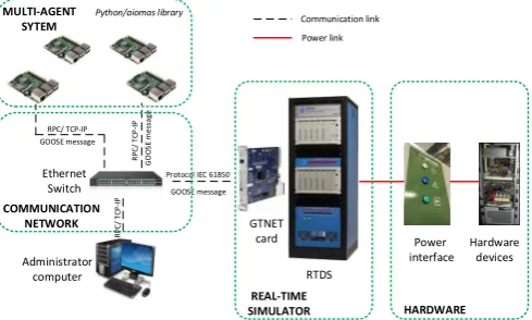
Fig. 1:Overview of the laboratory platform.
A. Distributed Laboratory Platform
The validation and development of distributed control ap-proaches has been proven to be a difficult task to be carried out with accuracy and under realistic environments. In this case, a laboratory platform for improving the development and validation for distributed control concepts (mainly for power system use cases) has been accomplished. The platform consists of two main sections: firstly a hardware-in-the-loop (HIL) capability with real-time simulation and secondly a multi-agent system (MAS) platform with a realistic commu-nication network. With this implementation realistic testing of power components and its interactions under distributed control scenarios can be studied with more detail and more precise conclusions can be reported from the power system focus of the validation process. The MAS hardware setup with realistic communications allows for the same detail of testing as the power system side but with the focus on the distributed control algorithms (scalability, robustness, cyber-security, etc.) and the always important communication infrastructure. In Fig. 1 the structure of the distributed control platform is presented. The platform is mainly divided into two sections, the HIL section and the MAS capability.
HIL allows for the validation of different types of compo-nents for power systems by performing controller-HIL (CHIL) and power-HIL (PHIL) [19]. Typically CHIL is used for the validation of controller and protection devices (or other similar devices that only require of low voltage signals which the RT simulator can generate). While PHIL is used for the validation of power components and the analysis of the dynamics and interactions of such devices. For this paper a combination of PHIL and CHIL is proposed in which the power component of the PHIL will be a power inverter, while for the CHIL the MAS is used.
For both of the implementations a digital real time simulator (DRTS) is required. The DRTS is responsible for simulating larger parts of the power system that are not typically available in a laboratory environment, as it is typically the case for system level testing. The real time aspect of the simula-tions support the interconnection with other real hardware
components for CHIL and PHIL setups. Interfaces between these need to be carefully assessed as sometimes can be a source of inaccuracies and instabilities, specially for PHIL implementations.
1) PHIL with power inverter: The testing of distributed controllers can significantly improve by adding one more layer of reality to the experiments by driving real hardware components with the controller under test. By using this approach, real communication will be present between the controller and the actual hardware device, at the same time the dynamics that the hardware device can introduce (noise in measurements, fast dynamics and others) will enhance the validation of the resilience of the distributed control algorithm. Furthermore, developments towards real implementation can be achieved as real initialization of the control to avoid damage to the hardware components and real limits of the hardware have to be taken into account, this being an aspect typically overlooked when controllers are validated by simulation only. In this case one of the controllable devices (power inverter) is interfaced with the rest of the power simulation in the DRTS with the use of a power amplifier in a PHIL setup, using an ideal transformer method (ITM) interface algorithm that employs an analog communication link [20]. In order to improve the accuracy of such implementation a time delay compensation algorithm as in [21] is also implemented.
2) CHIL with MAS platform and a realistic communication network: The MAS platform is a cluster of Raspberry PI (RPI) connected through a local area communication network in the laboratory. The RPI is a small, powerful, cheap, fully customizable and programmable computer board. It allows for developing MAS software in pure Python language. De-pending on the specifics of the distributed algorithm and its application, the agents of the MAS may represent individual buses or an area of power system.
The communication between the different agents in the MAS platform can be configured to correspond with any network topology. The inter-agent data can be transmitted in a physical local area network, although the data can be intercepted by a communication emulator software which would add realistic communications network effects of the desired topology and technology of the network. Therefore the convergence of distributed control implementations and its impact to the power system operation could be evaluated more realistically. Moreover, the disturbance of communication (i.e. latency, packet loss, jitter, etc.) could be added directly to the network to analyze the performance and the stability of system. A host computer is used for sending remote commands to the RPIs, for initialization and visualization of the agent interaction within the network.
indus-trial applications, allowing for a more realistic validation of distributed control algorithms.
B. Validation Chain
To validate the distributed frequency control algorithm, a validation chain proposed in [22], is employed. The testing chain comprises of four steps:
In the first step, the feasibility of the approach, i.e., the distributed control algorithms, is proven by means of pure simulations. At this early stage, the implementation of the algorithm is centralized in implementation to prove the stable operation in conjunction with a power network. Communica-tion delays are ignored or deterministic static delay employed. The second step involves the distributed implementation of the algorithm to ensure their convergence. This provides preliminary proof of feasibility of the distributed approach.
The following step,step three, is the CHIL implementation of the distributed algorithm. The algorithm is prototyped into physical hardware controllers running at designed time-step. Such an implementation is important as it more often reveals hidden implementation errors that might be masked by pure simulation approaches, either due to small time-step that is utilized for accurate representation of power components or due to missing control information that is intrinsically avail-able within pure simulations. Furthermore, at this stage, due to the controllers being implemented within a physical controller, communications delay is inherently incorporated. However, it is also possible for utilization of dedicated communications emulation tools.
The final step, step four, is a combined controller and power hardware in the loop implementation. This final step ensures the feasibility of the proposed approach to operate with real measurements, that often incorporates noise. In addition, utilizing a hardware component as a controllable device, being controlled by the proposed distributed algorithm, further provides evidence of the controls employability in real-world.
III. VALIDATION OFDISTRIBUTEDFREQUENCYCONTROL
ALGORITHM
A. Description
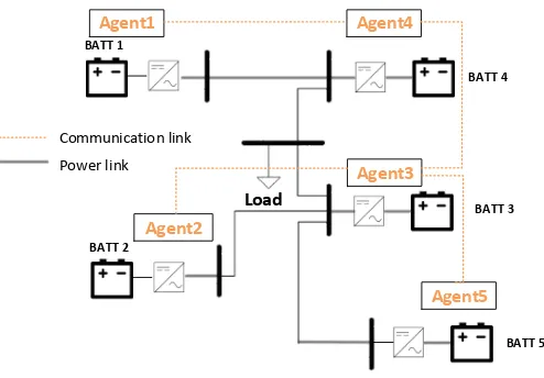
The distributed control algorithm chosen for validation is a secondary frequency control algorithm for islanded microgrids as proposed in [18]. Accordingly, an islanded AC microgrid supplied by five energy storage systems (ESS) is chosen as the test network and is shown in Fig. 2. The ESS inverters operate in parallel, and are controlled as grid-forming converters, controlling grid frequency and voltage [23]. The performance of the distributed secondary frequency control algorithm will be assessed under two scenarios: a step up and a step down of load. The complete test setup is shown in Fig. 3, with implementation details presented below:
1) Real-time simulation and PHIL: The microgrid and local controllers of the simulated inverters were implemented in RTDS. A hierarchical control structure is used for the control of the inverters. A droop-based primary control is designed
BATT 2
Load
Agent1
Agent3
Agent2
Agent4
Agent5 BATT 1
BATT 4
BATT 5 BATT 3
[image:3.595.307.554.61.233.2]Communication link Power link
Fig. 2:The test case microgrid and communication network.
to stabilize voltage and frequency under variations of the grid conditions. This is a decentralized (local) control layer and therefore only requires local measurements. This fast response is required for containing the deviations in voltage and current within a safe band. The implemented secondary control in the inverters is based on proportional-integral (PI) controllers with the aim of restoring deviations caused by primary control, i.e., to restore the frequency to its nominal value. The microgrid power system comprises five ESSs, one load and power lines. For the introduction of real dynamics into the test case, the system is divided into two sections: section 1 is composed of ESS 1 which is the hardware battery, emulated by the inverter, with its corresponding local controller, and section 2 is composed of the remaining elements of the microgrid simulated within the real-time simulator from RTDS Tech-nologies. The local frequency deviation at each inverter point of connection is measured and sent to the corresponding RPI agent via IEC61850 protocol with GOOSE messages. In this implementation frequency measurement from the hardware device is sent to the RTDS with analog communication, which is then re-routed to the corresponding RPI agent.
RTDS GTNET card Ethernet Switch Administrator computer MULTI-AGENT SYTEM Power interface Hardware devices
Protocol IEC 61850
GOOSE message COMMUNICATION NETWORK HARDWARE REAL-TIME SIMULATOR GOOSE message RPC/ TCP-IP R P C / T C P -IP G O O SE m es sa ge R PC / TC P -IP ESS 2 Load
ESS 1 ESS 4
ESS 5 ESS 3 Agent1 Agent2 Agent3 Agent4 Agent5
[image:4.595.51.543.60.260.2]Experiment test bench
Test case diagram
Fig. 3:The experiment test bench.
a)
b)
c)
d) 0 0.1 0.2
∆ f [ H z ] agent 1 ESS 1 agent 2 ESS 2 agent 3 ESS 3 agent 4 ESS 4 agent 5 ESS 5 0 0.05 0.1 0.15
∆ fav er ag e [ H z ]
49.8 49.9 50
f
[Hz]
0 2 4 6 8 10 12 14 16 18 20 22 24 26 28 30
5 10 15 Time [s] P [kW]
t1 t2
a)
b)
c)
d)
0
0
.
1
0
.
2
∆
f
[
H
z
]
agent 1
ESS 1
agent 2
ESS 2
agent 3
ESS 3
agent 4
ESS 4
agent 5
ESS 5
0
0
.
05
0
.
1
0
.
15
∆
f
av
er
ag
e
[
H
z
]
49
.
8
49
.
9
50
f
[Hz]
0
2
4
6
8
10
12
14
16
18
20
22
24
26
28
30
5
10
15
Time [s]
P
[kW]
[image:4.595.43.296.289.615.2]t
1
t
2
Fig. 4:Load increasing step scenario.
a) The state values of agents. b) Consensus values sent to controllers from agents. c) Frequency values measured at output of ESSs. d) Active power output of ESSs.
B. Results
The results only from the combined controller and power hardware-in-the-loop implementation are presented in interest
a)
b)
c)
d)
−0.3
−0.2
−0.1
0 ∆ f [ H z ] agent 1 ESS 1 agent 2 ESS 2 agent 3 ESS 3 agent 4 ESS 4 agent 5 ESS 5
−0.2
−0.1
0 ∆ fav er ag e [ H z ] 50 50.1 50.2 50.3
f
[Hz]
0 2 4 6 8 10 12 14 16 18 20 22 24 26 28 30
0 5 10 15 Time [s] P [kW]
t1 t2
a)
b)
c)
d)
−
0
.
3
−
0
.
2
−
0
.
1
0
∆
f
[
H
z
]
agent 1
ESS 1
agent 2
ESS 2
agent 3
ESS 3
agent 4
ESS 4
agent 5
ESS 5
−
0
.
2
−
0
.
1
0
∆
f
av
er
ag
e
[
H
z
]
50
50
.
1
50
.
2
50
.
3
f
[Hz]
0
2
4
6
8
10
12
14
16
18
20
22
24
26
28
30
0
5
10
15
Time [s]
P
[kW]
t
1
t
2
Fig. 5:Load decreasing step scenario.
a) The state values of agents. b) Consensus values sent to controllers from agents. c) Frequency values measured at output of ESSs. d) Active power output of ESSs.
of brevity and space.
[image:4.595.306.557.298.615.2]1.2 1.3
agent 1
consensus
time
[s]
1.2 1.3
agent 2
1.2 1.3
agent 3
1.2 1.3
agent 4
1.2 1.3
[image:5.595.47.289.48.160.2]agent 5
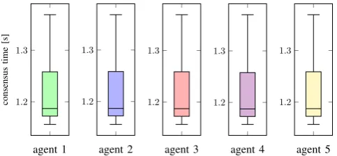
Fig. 6:Consensus time.
the load are simulated. In the first scenario, the load power is increased by11kW. The results of scenario 1 are presented in Fig. 4. The state values of agents in each iteration are shown in Fig. 4a. As can be seen from Figure 4d, when the load is increased, the power output of all ESSs increases to balance the power and stabilize the system. The frequency is displaced from the nominal frequency in accordance with local droop control in the primary control layer as observed in Fig. 4c.
The average consensus implemented in the agents is an iterative algorithm, the state of an iteration is computed based on the state of previous iteration and exchanged information with neighborhood agents. The initial state is the frequency deviation at the local point of connection of the inverter received through GOOSE messages sent from RTDS. When finishing a consensus process at the final iteration, the agent will send the value of its state to the corresponding controller (the values shown in Fig. 4b). In order to bring frequency back to the reference value, as the requirement of the secondary control of inverters, consensus processes in all agents need to converge concurrently at an analogous value.
In order to show the operation of a consensus process, we consider the duration from t1 to t2 as illustrated in
Fig. 4a. At t1, all agents have received new initial states,
i.e., the local frequency deviations. The agents implement the consensus algorithm and obtain the convergence at t2.
The results are then sent to the corresponding controllers to finish the consensus process. The new consensus is begun upon receiving new initial state by means of updating the measurements. The consensus values that RTDS received from the agents can be observed in Fig. 4b. We can see that the values are almost all the same that meets the requirement of the control system. Consequently, the frequency of the grid system was restored accurately to its nominal value within approximately 30sof the occurrence of the disturbance.
A small transient can be observed in the frequency trace of the hardware inverter of Fig. 4c, which is introduced by the control of the converter. The cause of the transient was not known at the time of the conduction of the experiments but was later deduced as the clock reset due to overflow of a fixed integer value within the converter control. This transient was not due to the implemented control, rather a characteristic of the test hardware utilized. This further validates the control algorithm under unknown circumstances as it does not actively
react negatively to this minor transient.
The results of the experiment with step down of 12kW of load are shown in Fig. 5. When the disturbance occurs, the frequency of the system displaced (increases) from the nomi-nal value. With the multi-agent system running the distributed consensus algorithm, the frequency deviation is eliminated in a similar manner to as in scenario 1, validating the algorithm under realistic dynamics and communications in a laboratory setup.
2) Communication network performance: In the experi-ment platform, a real laboratory network was used to transfer data between RPIs. The time of a consensus process in an agent consists of the time of the computation for updating state and the time delay due to transferring data between agents. Therefore, the speed of convergence depends on the complexity of system and quality of communication network. By using the designed platform, the influence of network performance to control system can be considered.
The controller of an inverter has to wait for a consensus process in agents to finish before receiving a new control signal. Therefore the performance of network can significantly affect the control system which in turn may cause instabilities in the grid. The statistics of the time for a consensus process are shown in Figure 6. The time is calculated based on logging operation of agents in the scenario 1. There are about 280 processes recorded in each agent. The time for a consensus process is mainly in the range from 1.17s to 1.26s. The consensus time in all agents is almost the same expressed that the unity of computation in the multi-agent system to send analogous signals to controllers.
IV. CONCLUSION
This contribution presented laboratory setup for systems level validation of distributed control algorithms for power systems. The distributed frequency control was validated under CHIL and PHIL employment with realistic communication network. This work proved the feasibility of utilizing dis-tributed consensus algorithm for secondary frequency control in autonomous microgrids under realistic conditions.
REFERENCES
[1] D. K. Molzahn, F. D¨orfler, H. Sandberg, S. H. Low, S. Chakrabarti, S. Member, R. Baldick, and J. Lavaei, “A Survey of Distributed Optimization and Control Algorithms for Electric Power Systems,”IEEE Transactions on Smart Grid, vol. 8, no. 6, pp. 2941–2962, 2017. [2] “Distributed optimization approaches for emerging power systems
oper-ation: A review,”Electric Power Systems Research, vol. 144, pp. 127– 135, 2017.
[3] M. Yazdanian, A. Mehrizi-sani, G. S. Member, and A. Mehrizi-sani, “Distributed Control Techniques in Microgrids,”IEEE Transactions on Smart Grid, vol. 5, no. 6, pp. 2901–2909, 2014.
[4] J. W. Simpson-Porco, Q. Shafiee, F. Dorfler, J. C. Vasquez, J. M. Guerrero, and F. Bullo, “Secondary Frequency and Voltage Control of Islanded Microgrids via Distributed Averaging,”IEEE Transactions on Industrial Electronics, vol. 62, no. 11, pp. 7025–7038, 2015. [5] M. Josep, J. C. Vasquez, Q. Shafiee, S. Member, J. M. Guerrero,
S. Member, and J. C. Vasquez, “Distributed Secondary Control for Islanded MicroGrids - A Novel Approach,”IEEE Transactions on Power Electronics, 2014.
[7] M. Ma, S. Member, L. Fan, S. Member, Z. Miao, and S. Member, “Consensus ADMM and Proximal ADMM for Economic Dispatch and AC OPF with SOCP Relaxation,” in 2016 North American Power Symposium (NAPS), no. 2, 2016, pp. 1–6.
[8] P. Stadler, A. Ashouri, and F. Marechal, “Distributed Model Predic-tive Control for Energy Systems in Microgrids,”Systems Conference (SysCon), pp. 1–12, 2016.
[9] S. D. J. McArthur, E. M. Davidson, V. M. Catterson, A. L. Dimeas, N. D. Hatziargyriou, F. Ponci, and T. Funabashi, “Multi-Agent Systems for Power Engineering Applications-Part I: Concepts, Approaches, and Technical Challenges,”IEEE Transactions on Power Systems, vol. 22, no. 4, pp. 1743–1752, 2007.
[10] C. M. Colson and M. H. Nehrir, “Comprehensive real-time microgrid power management and control with distributed agents,”IEEE Transac-tions on Smart Grid, vol. 4, no. 1, pp. 617–627, 2013.
[11] H. N. Aung, A. M. Khambadkone, D. Srinivasan, and T. Logenthiran, “Agent-based intelligent control for real-time operation of a microgrid,”
2010 Joint International Conference on Power Electronics, Drives and Energy Systems, PEDES 2010 and 2010 Power India, 2010.
[12] M. Chen, M. H. Syed, E. G. Sansano, S. D. J. McArthur, G. M. Burt, and I. Kockar, “Distributed negotiation in future power networks: Rapid prototyping using multi-agent system,” in2016 IEEE PES Innovative Smart Grid Technologies Conference Europe (ISGT-Europe), Oct 2016, pp. 1–6.
[13] E. Guillo-Sansano, M. H. Syed, A. J. Roscoe, G. Burt, M. Stanovich, and K. Schoder, “Controller hil testing of real-time distributed frequency control for future power systems,” in2016 IEEE PES Innovative Smart Grid Technologies Conference Europe (ISGT-Europe), Oct 2016, pp. 1– 6.
[14] A. Razaq, B. Pranggono, H. Tianfield, and H. Yue, “Simulating smart grid: Co-simulation of power and communication network,” in2015 50th International Universities Power Engineering Conference (UPEC), Sept 2015, pp. 1–6.
[15] I. Ahmad, J. H. Kazmi, M. Shahzad, P. Palensky, and W. Gawlik, “Co-simulation framework based on power system, ai and communication tools for evaluating smart grid applications,” in2015 IEEE Innovative Smart Grid Technologies - Asia (ISGT ASIA), Nov 2015, pp. 1–6. [16] H. Kim, K. Kim, S. Park, H. Kim, and H. Kim, “Cosimulating
commu-nication networks and electrical system for performance evaluation in smart grid,”Applied Sciences, vol. 8, no. 1, 2018.
[17] P. Dambrauskas, M. Syed, S. Blair, J. Irvine, I. Abdulhadi, G. Burt, and D. Bondy,Impact of realistic communications for fast-acting demand side management, 3 2017.
[18] T. L. Nguyen, Q. T. Tran, R. Caire, C. Gavriluta, and V. H. Nguyen, “Agent based distributed control of islanded microgrid - real-time cyber-physical implementation,” in 2017 IEEE PES Innovative Smart Grid Technologies Conference Europe (ISGT-Europe), Sept 2017, pp. 1–6. [19] V. H. Nguyen, Y. Besanger, T. Tran Quoc, N. Tung Lam, C. Boudinet,
R. Brandl, F. Marten, A. Markou, P. Kotsampopoulos, A. Van Der Meer, E. Guillo-Sansano, G. Lauss, T. I. Strasser, and K. Heussen, “Real-Time Simulation and Hardware-in-the-LoopApproaches for Integrating Renewable EnergySources into Smart Grids: Challenges & Actions,” in
IEEE PES Innovative Smart Grid Technologies Asia 2017, Auckland, New Zealand, Dec. 2017.
[20] R. Brandl, “Operational range of several interface algorithms for dif-ferent power hardware-in-the-loop setups,” Energies, vol. 10, no. 12, 2017.
[21] E. Guillo-Sansano, A. J. Roscoe, and G. M. Burt, “Harmonic-by-harmonic time delay compensation method for phil simulation of low impedance power systems,” in2015 International Symposium on Smart Electric Distribution Systems and Technologies (EDST), Sept 2015, pp. 560–565.
[22] M. Maniatopoulos, D. Lagos, P. Kotsampopoulos, and N. Hatziargyriou, “Combined control and power hardware in-the-loop simulation for testing smart grid control algorithms,” IET Generation, Transmission Distribution, vol. 11, no. 12, pp. 3009–3018, 2017.