City, University of London Institutional Repository
Citation
:
Grandal, T., Zornoza, A., Lopez, A., Fraga, S., Sun, T. ORCID:
0000-0003-3861-8933 and Grattan, K. T. V. ORCID: 0000-0003-2250-3832 (2019). Analysis of Fiber optic
sensor embedding in metals by automatic and manual TIG welding. IEEE Sensors Journal,
19(17), pp. 7425-7433. doi: 10.1109/JSEN.2019.2916639
This is the accepted version of the paper.
This version of the publication may differ from the final published
version.
Permanent repository link:
http://openaccess.city.ac.uk/id/eprint/22003/
Link to published version
:
http://dx.doi.org/10.1109/JSEN.2019.2916639
Copyright and reuse:
City Research Online aims to make research
outputs of City, University of London available to a wider audience.
Copyright and Moral Rights remain with the author(s) and/or copyright
holders. URLs from City Research Online may be freely distributed and
linked to.
City Research Online:
http://openaccess.city.ac.uk/
[email protected]
Abstract—In this paper, the embedding of fiber optic sensors in metals, by using both automatic and manual Tungsten Inert Gas welding (TIG) is discussed for nickel- and copper-coated Fiber Bragg Gratings (FBG) written into an optical fiber, as embedding such sensors in metals provides protection against environmental effects. In the investigation and analysis of the performance of a number of such sensors, copper-coated sensors were seen to lose their temperature and strain sensitivity while being embedded due to damage to the coating, while with a nickel coating the sensors in the fiber were found to withstand the process with a lesser effect on the sensor performance. The research has also shown that the Automatic TIG process used is less invasive than the manual TIG approach, although more expensive to implement.
Index Terms—Fiber optic sensors, metal embedded fiber optic sensors, TIG welding, Fiber Bragg Gratings.
I. INTRODUCTION
he fourth industrial revolution, also called Industry 4.0, requires sensor integration in tools, materials and machines for accurate, real time monitoring of many important systems and processes. Prior research has found that with composite materials, sensors can be easily embedded during the manufacturing process and they have, for example, been used successfully by some of the authors for the monitoring of innovative composite bridge structures [1]. In many cases, cheaper conventional sensors such as piezoelectric accelerometers, strain gages or thermocouples can be employed if the monitoring conditions suit, although there are a number of specialist areas where this is not the case and optical fiber methods are to be preferred [2,3]. For metals, however, it can be a real challenge to incorporate sensors effectively: the manufacturing process operates at high temperatures and applications often include harsh environments, which conventional sensors are not easily able to withstand. Fiber optic sensors (FOS) present numerous advantages that suit them well to operation in these harsh environments, where issues
This paper was supported by the project Unidad mixta de investigación NEXT BEARINGS with reference IN853A 2015/2, funded by the Spanish general government administration and the Xunta de Galicia through GAIN and the Ministry of Industry, Energy and Tourism of Spain. T. S. and K.T.V.G. authors acknowledge the support of the Royal Academy of Engineering.
T.G. Author is with Aimen Technology Centre National, O Porriño, Pontevedra, 36410, Spain and the the School of Mathematics, Computer Science and Engineering, City, University of London, Northampton Square, London, EC1V 0HB, United Kingdom (e-mail: [email protected]).
A.Z. Author is with the Departamento de matemática aplicada at Universidad del País Vasco, Eibar, 20600, Spain (e-mail: [email protected]).
such as electromagnetic immunity, small size, the possibility of multiplexing many sensors and simultaneous monitoring several parameters in different positions in one single fiber are critically important [2].
In most current applications, usually FOS are glued on the surface of metals, as typically is done in the monitoring of bridges and reinforcement bars [3] but the long-term degradation of adhesives and glues can affect the measurand, often then inducing unexpected errors, for example those caused by a decrease in the strain transfer as the adhesion weakens. Embedding FOS into metallic structures can avoid these problems (and the consequent resultant errors) and thus the challenge of creating a satisfactory and reproducible way to do this must be tackled. The experience of the authors has shown that to be effective when embedding an FOS into metallic materials, the fiber must be coated with a metal layer. Such a coating mechanically protects the fiber from the high temperatures and mechanical loads experienced during the embedding process [4]. In addition, they affect the bonding to the metal, which can be compromised by slippage or delamination [5], [6]. The earliest solutions presented for embedding FOS into metals were based on deposition techniques. In this case, the total diameter of the fiber needed to withstand the embedding process was often as large as 2mm, making it significantly larger when compared to typical communications-based optical fiber (cladding ~125m diameter) [7]. Ultrasonic welding and vacuum brazing have also been proved to be valid solutions for joining the fiber to metal, although the low temperature of the process limits the application of the sensors in the first instance [8] and the complexity, cost and need for a vacuum chamber limits the flexibility of the second [9]. Techniques based on Selective Laser Melting have shown promising results due to the possibility there is for precise thermal control of the process, to create protective coatings of up to 350m total diameter [5], but it is hard to expand this to production levels and be sufficiently flexible for different materials to be used. Finally, an
A.L. and S.F authors are with Aimen Technology Centre National, O Porriño, Pontevedra, 36410, Spain (e-mails: [email protected] and [email protected]).
J.A.V author is with Wärtsilä iberica, O Porriño, Pontevedra, 36475, Spain (e-mail: [email protected]).
T. S. and K.T.V.G. authors are with the School of Mathematics, Computer Science and Engineering, City, University of London, Northampton Square, London, EC1V 0HB, United Kingdom (e-mails: [email protected] and [email protected]).
Analysis of Fiber optic sensor embedding in
metals by automatic and manual TIG welding
T. Grandal, A. Zornoza, A. López, S. Fraga, T. Sun and K. T. V. Grattan
embedding process using a laser beam to create a cladding has also been demonstrated to provide flexibility in manufacturing, since no vacuum or gas chamber is needed for the process and optical fibers with nickel coatings (of total diameter ~300m) can be successfully embedded [10]. However, the employment of high-power lasers for this LMD (Laser Metal Deposition) process, to create the necessary level of heating needed, makes the technique very expensive.
It is clear that more cost-effective and simpler techniques, better suited to use eventually in a production environment are required. In this paper the use of Tungsten Inert Gas (TIG) welding is discussed as an effective means to achieve FOS embedding in metals, at low cost and in a way that makes it suitable for using in a number of different applications. TIG welding is an arc electric welding process, involving the use of a shielding gas and a non-consumable tungsten electrode [11]. The arc is established between electrode and the piece to be welded, and filler metal can be added independently. Two different TIG welding variants are studied in this work to evaluate which is the most effective, these being both automatic and manual welding. In the automatic TIG welding process, the parameters involved in the process are selected prior to the use of the welding process. By contrast, in the TIG manual process, it is only the current used which is a priori defined, with all the other parameters for the welding conditions usually depending of the experience of the technician undertaking the weld, based on the techniques familiar from the literature [11]. Repeatable and high accuracy automatic TIG welding techniques are available, as is the less repeatable, yet highly-adaptable and portable manual TIG welding technique. Both techniques are low-cost in comparison to the other techniques used for FOS embedding and have the advantage of being familiar, being used in many industries in the metal-mechanic sectors, this being especially true of the widely-used manual TIG approach.
In this work, to evaluate and optimize the techniques described to create metal-clad sensors, Fiber Bragg Grating-based sensors (FBG) in optical fiber have been chosen, as these are widely used in many different sensor applications [12] where ruggedized sensors are needed. FBGs can easily be designed and written into a short, 5mm length of optical fiber, forming the basis of the sensor. As high
temperatures are reached during the welding processes studied, the FBG-based sensors selected where written by using a femtosecond laser to ensure they survived that heating process. Thus FBGs were designed to withstand temperatures up to 1000oC, without the danger of the grating being
erased or damaged by the welding process. The design of embedded sensors discussed will allow them to operate by reflecting light on a narrow wavelength band (less than 1pm) from the incident white light signal, monitoring the reflected wavelength variation caused by changes such as in temperature and strain. FBG-based sensors have been used for different applications, over many years, where metal embedding of FOS
has been shown to be particularly valuable [3], [5]-[9] and thus are an ideal choice for the sensors demonstrated in this work.
II. EXPERIMENTAL SETUP
As has been discussed in the Introduction, TIG welding is an arc electric welding process using a shielding gas and a non-consumable tungsten electrode, where an electric arc is established between the electrode and the piece to be welded, allowing filler metal to be independently added. For this work, the added material used comes from a wire of 1.6mm diameter tin alloy, with composition Sn7.5Sb3.5Cu. This alloy has a melting point of 250oC, but during the welding process higher
temperatures are achieved, up to 700oC. The specimens into
which the optical fibers and sensors are embedded are made of forged steel, type ST52, with a thin alloy coat as the metal, into which coating the FOS are embedded.
The materials chosen for the protective coatings for the sensors were nickel and copper (due to their high melting points, durability, cost and ease of use). In addition, these metals have already been used in previous studies and a good performance has been achieved with them [10], [11]. While evaluating the many techniques reported to coat optical fibers [4]-[6], it was found that the same techniques reported by us previously in the literature [10] were the most suitable and thus were chosen. In this process, first a layer of gold of 2µm thickness was deposited on the optical fiber using a sputtering process. This layer gives the optical fiber the necessary conductivity prior to the application of the second step, where it is coated with nickel or copper, achieving the desired thickness by use of electroplating deposition. The embedding strategy for the sensor-based fibers produced using each of the techniques is explained in detail below.
A. Automatic TIG Embedding process
In Fig. 1, the automatic TIG welding setup which was employed in this work is shown. An automatic TIG welding set-up with an FMW-Multi Welding System (Fronius), Magic Wave 5000 and KD 1500 D-11 and a torch, also from Fronius, were used as the welding machine and the device to guide the wire, respectively. During the embedding trials, the optimum welding conditions established from our previous experience
(a) (b)
Fig. 1. (a) Automatic TIG welding setup used in this work showing the device to guide the wire and the torch and (b) a close-up of this key part of the set up.
were set, these being: a wire diameter of the tin alloy of 1.6mm; the use of a non-consumable electrode of 1% lanthanum (class EWLa-1 according to the American Welding Association) with 1.6mm diameter; as shielding gas 100% Argon; a direct pulsed current and with the electrode connected to the negative pole. The other main TIG operational parameters which were adjusted to achieve this optimum embedding process were as follows: an average current of 35-40A; a travel speed of 0.4 m/min; a wire speed 1.5 m/min and a torch position relative to the fiber of 1.5-2mm.
B. Manual TIG embedding process
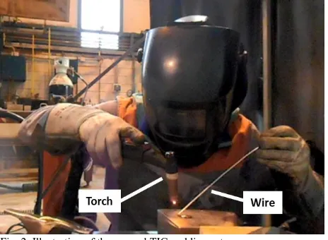
In Fig. 2, the manual TIG welding setup employed in this work is shown. This had been used in some of our prior work [11], in which the optical fiber containing the sensors was positioned on top of the material on which it is to be embedded and the wire from the TIG was melted on top of, or close to, the optical fiber. Our previous experience has shown that manual TIG embedding of optical fibers and sensors should be performed by a skilled technician as, being a technique with a significant component of operator skill, experience and
know-how, the technician’s skill brings these key elements for the success of the process and thus in regularly achieving a ‘good weld’.
III. RESULTS
A. Embedding optical fibers
One of the main advantages of the use of FOS is how minimally invasive they are, due to their small size. For example, with TIG embedding, once the optical fiber or sensor is embedded, the total thickness of the tin alloy-coated layer in the forged steel specimens is still very small, at ~3mm. However, the metallic coating needed for protection in the metallic embedding process compromises this, so one parameter of interest is the minimum embeddable coated optical fiber diameter that ensures that both the integrity of the fiber and sensor are maintained, while the fiber is kept minimally invasive. Thus, its presence does not compromise the usability of the manufactured metallic part. In the case of using automatic TIG, several tests were performed (based on the process described in our prior work [10]) to estimate the
minimum coating needed for successfully embedding the optical fibers and sensors. A first step was to use relatively coarse tuning, with different coating thicknesses on the optical fibers to help to define the best embedding strategy. In this first step a ‘red-light’ optical fiber fault detector was used to estimate any damage caused to the optical fiber by the process. In the second step, various optical fibers with different thicknesses were embedded and any loss of the fiber was monitored, this being an indicator of the damage suffered by the optical fiber itself. For the manual TIG process, the results reported in prior works were supplemented with those created from new tests [9]. Thus, the minimum embeddable diameters, determined as a function of the technique used and the coating material employed, are listed in Table I. It should be noted that nickel coatings of lower thicknesses than before can be embedded, this being attributed to the higher melting point (1455ºC) for nickel, when compared to that for copper (1085ºC) and to the thermal conductivity of each material. The thermal conductivity of the Cu is higher than that of Ni, which makes that the heat generated during the welding process travel faster to the fiber cladding and core, causing damage to the fiber if the coating layer is not sufficiently thick. Also, the Automatic TIG process allows lower coating thicknesses to be used than for the manual TIG, this being attributed to the greater accuracy achievable from the automatic TIG process and because is a faster process (where the high temperatures reached can dissipating faster avoiding the fiber damage).
B. Embedding FBGs
[image:4.612.51.283.311.481.2]To evaluate the performance of the embedded optical fiber sensors created, metal-coated FBGs were embedded in metallic specimens, these being designed to allow temperature and tensile tests on them to be performed. The FBGs used in the work were manufactured by using a femtosecond laser-based manufacturing process (from Femto Fiber Tec), where the grating was of 5mm length and the optical fiber for this sensor was type SMF-28. The FBG fabrication process used was chosen (over the use of a nanosecond phase mask-based method) to allow them better to withstand the high temperatures of the embedding process [1] with the coating process described in Section 2. The FBG coatings were chosen to have sufficient thickness to withstand the embedding process, this being based on our previous experience, as described in Section 2. Four FBGs were used these being as follows: (a) a 464 µm total diameter nickel-coated FBG with automatic TIG embedding; (b) a 592 µm total diameter copper-coated FBG with automatic TIG embedding; (c) a 526 µm total diameter nickel-coated FBG for manual embedding and (d) a 738 µm copper-coated FBG, again for manual TIG welding. With such FBGs, the
Fig. 2. Illustration of the manual TIG welding set-up
TABLEI
MINIMUM COATING DIAMETERS OF SUCCESSFULLY EMBEDDED OPTICAL FIBERS
Minimum embeddable coating diameter of optical fibers (m) ± 5µm Coating material Automatic TIG Manual TIG
Nickel 236 322
[image:4.612.315.556.402.466.2]performance of metal embedded sensors obtained with both the automatic and manual TIG and both copper- and nickel- coated FBGs can readily be compared. In Fig. 3, the four specimens with the embedded sensors using TIG welding are shown, where the better accuracy achieved in the deposition of the metal can be observed for the automatic TIG embedded FBGs, (Fig. 3(a) and (b)), than is seen for the manual TIG embedded specimens, (Fig. 3(c) and (d)). The embedding depth for each FBG sensor is a little different, as Table II shows, despite the fact that the diameter of wire used as the added material was the same for all of them.
FBG-based sensors are widely used for their sensitivity to strain and temperature. Recognizing this, three characterization tests were performed on the embedded sensors, as follows: (1) a spectral analysis of these embedded sensors before and after having been embedded, (2) temperature tests in a Lentong TLK38 oven; (3) tensile tests in an MTS landmark 250kN tensile testing machine and (4) destructive metallography tests. The first of these tests, (1), (2) and (3), have been used to help evaluate the performance of the embedded FBGs and the last, (4), the quality of the embedding process itself.
1) Spectral analysis
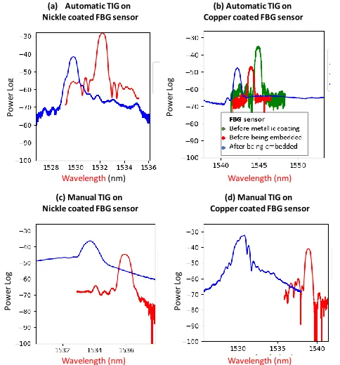
A first method used to evaluate the quality of the process of embedding of the FBG sensors is to analyze and compare the spectrum of the sensors before and after having been embedded. In the Fig. 4, the spectra for the coated FBG sensors before and after being embedded are shown. It can be noted that here the femtosecond laser-written FBG sensors have a spectrum that is
wider (at 0.75nm, FWHM) and of lower reflectivity than the UV-laser written FBG sensors. Further, as Fig. 4(b) shows, the signal amplitude observed after the metallic coating is applied is lower than that in the previous case and the sensor is compressed because of the coating layer. In the case of the sensors embedded by using the automatic TIG welding process (Fig. 4(a) and 4(b)), the wavelength variation seen is around 2nm after the embedding process occurs. In this case, the signal amplitude has fallen, while the peak shape is similar to that seen previously. Looking these spectra, it would appear that the FBG sensors are well embedded, with a good bond from the
[image:5.612.81.519.64.231.2]added and the base material. However, in the case of the FBG sensors embedded by using the manual TIG welding process, the sensors are more affected. Here, the spectra observed after the embedding process has occurred show a lower amplitude and in the case of the Cu-coated FBG sensor, the peak presents a high level of asymmetry. The wavelength shift for the Ni coated FBG sensor embedded by manual TIG welding (Fig. 4(c)), is around 2nm, similar to the previous sensors embedded by use of the automatic TIG welding process. However, for the Cu-coated FBG sensor, the wavelength shift is around 8.5nm, which is a higher variation, in comparation to what previously was observed. From these results, is easy to conclude that the Cu-coated FBG sensor, embedded by using manual TIG welding has a poor adhesion with the base and the added
Fig. 3. Samples with embedded FBGs created as described above by (a) automatic TIG on nickel-coated FBG, (b) automatic TIG on copper-coated FBG, (c) manual TIG on nickel-coated FBG and (d) manual TIG on copper-coated FBG.
Fig. 4. Spectra taken after and before embedding process for (a) automatic TIG on nickel-coated FBG, (b) automatic TIG on copper-coated FBG, (c) manual TIG on nickel-coated FBG and (d) manual TIG on copper-coated FBG.
(b) Automatic TIG on Copper coated FBG sensor
(c) Manual TIG on Nickle coated FBG sensor
(d) Manual TIG on Copper coated FBG sensor (a) Automatic TIG on
Nickle coated FBG sensor
P
ow
er
Log
P
ow
er
Lo
g
P
ow
er
Log
P
ow
er
Log
Wavelength(nm) Wavelength (nm)
[image:5.612.321.563.432.692.2]material or the coating layer has deteriorated during the embedding process. Additionally, it is possible to determine that the manual TIG process is more aggressive when used with the metallic coated FBG sensors, than does the automatic welding process.
2) Temperature tests
To evaluate their temperature performance, the specimens created with the embedded sensors were evaluated over the range from 50oC to 200oC, in steps of 30oC. This ‘thermal
steps’ test was repeated three times to ensure the repeatability of the performance of the embedded sensors. The maximum temperature of the tests was limited by the tin alloy melting point, to that temperature of 250ºC. The results from the calibration steps are shown in Fig. 5 (a) to (d). A linear fit was observed for each sensor and ‘thermal step’ in order to obtain the thermal sensitivity for each. The response with wavelength is depicted in Fig. 6(a) to (d), for each specimen. The sensitivities measured are repeatable over the three calibration tests undertaken and the results are summarized in Table II.
Additionally, to obtain the thermal sensitivity before the coated FBG sensors were embedded, the same thermal test step, as used above was performed. As Table II shows, only for the Ni coated FBG sensor embedded by using the Manual TIG, was the same thermal sensitivity obtained as was seen
before it was embedded. In the case of the Ni-coated FBG sensor embedded by using automatic TIG welding, the thermal sensitivity obtained after the embedding process is higher than that observed previously. However, for the Cu-coated FBG sensors, the thermal sensitivity obtained after both embedding processes is lower than was seen for the previous process with the results being very close to each other. After the coated FBG sensors are embedded, the thermal sensitivity changes, because
[image:6.612.320.555.54.514.2]this depends of the embedding depth in the sample of each sensor and because of the thermal conductivity of the sensor coating used. In Table II, the embedding depth for each FBG sensor is shown. In the case of the Cu-coated FBG sensors, the
Fig. 5. Temperature tests on the embedded FBGs for (a) automatic TIG on nickel-coated FBG, (b) automatic TIG on copper-coated FBG, (c) manual TIG on nickel-coated FBG and (d) manual TIG on copper-coated FBG.
(b) Automatic TIG on Copper coated FBG sensor
(c) Manual TIG on Nickle coated FBG sensor
(d) Manual TIG on Copper coated FBG sensor (a) Automatic TIG on
Nickle coated FBG sensor
Time (h) W av el en gt h sh if t (n m ) W av el en gt h sh if t (n m ) W av el en gt h sh if t (n m ) W av el en gt h sh if t (n m ) Time (h)
Time (h) Time (h)
50oC
80oC
110oC
140oC
170oC
200oC
Fig. 6. Results of the calibration after the temperature tests on the embedded FBGs for (a) automatic TIG on a nickel-coated FBG, (b) automatic TIG on a copper-coated FBG, (c) manual TIG on a nickel-coated FBG and (d) manual TIG on a copper-coated FBG.
Temperature (oC)
W av el en gt h sh if t (n m )
(a) Automatic TIG on Nickle coated FBG sensor
Heat 1
y = 0.0293*x+(-0.7574) SD = 0.0183, R = 0.9951 Heat 2
y = 0.0288*x+(-0.6916) SD = 0.0126, R = 1.0000 Heat 1
y = 0.0285*x+(-0.6719) SD = 0.0168, R = 0.9999
(b) Automatic TIG on Copper coated FBG sensor
W av el en gt h sh if t (n m )
Temperature (oC)
Heat 1
y = 0.0273*x+(-0.7868) SD = 0.0359, R = 0.9997 Heat 2
y = 0.0267*x+(-0.6848) SD = 0.0331, R = 0.996 Heat 1
y = 0.0270*x+(-0.6662) SD = 0.0441, R = 0.9995
(c) Manual TIG on Nickle coated FBG sensor
W av el en gt h sh if t (n m )
Temperature (oC)
Heat 1
y = 0.0254*x+(-0.6575) SD = 0.0399, R = 0.9995 Heat 2
y = 0.0250*x+(-0.6770) SD = 0.0369, R = 0.9995 Heat 1
y = 0.0247*x+(-0.5813) SD = 0.0544, R = 0.9992
(d) Manual TIG on Copper coated FBG sensor
Temperature (oC)
W av el en gt h sh if t (n m
) Heat 1
y = 0.0284*x+(-0.8740) SD = 0.0594, R = 0.9991 Heat 2
y = 0.0283*x+(-0.8618) SD = 0.0393, R = 0.9996 Heat 1
y = 0.0280*x+(-0.7710) SD = 0.0804, R = 0.9986
TABLEII
SENSITIVITIES ACHIEVED BEFORE AND AFTER EMBEDDING THE FBGS
Embeddin g process Coating material Average Diameter before embedding
(µm)
Embedding depth (mm) Embedding lenght (mm) Sensitivity before embedding (nm/ºC) Sensitivity after embedding (nm/ºC)
Nickel 464 1.4 26 0.024 0.029
Copper 592 1.2 46 0.032 0.027
Nickel 526 1.2 20 0.025 0.025
Copper 738 1.3 17 0.034 0.028
Automatic TIG Manual
[image:6.612.63.289.284.520.2]thermal sensitivity is very close because the embedding depth is also very similar. However, in the case of the Ni-coated FBG sensors, the depth is higher for the Ni-coated FBG sensor embedded by using the Automatic TIG welding process, which causes the thermal sensitivity of this sensor to be higher than in the case of the Ni-coated FBG sensor embedded by use of the manual TIG welding process. Moreover, the thermal response for the Cu-coated FBG sensors embedded by use of the manual TIG welding process is repeatable and the sensitivity obtained is in accordance with that of the other FBG-embedded sensors and with the embedding depth used.
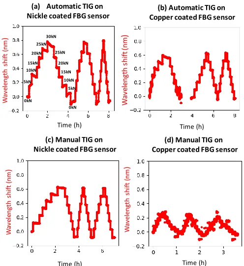
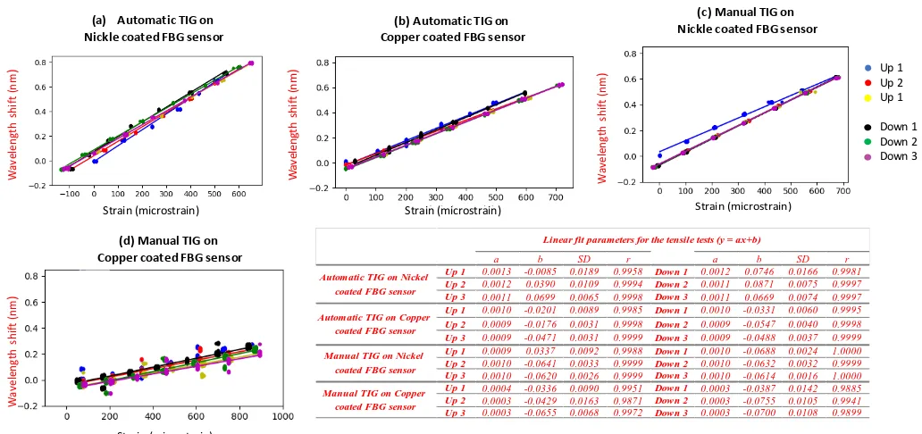
3) Tensile tests
In the strain calibration undertaken, three repetitions of the tensile tests were undertaken over the range from 0 to 30kN, in steps of 5kN, and performed for each specimen of the embedded sensor, as depicted in Fig. 7. In all three cases, the first of these tests shows a greater level of instability. This effect has already been discussed in the literature and is attributed to the residual strains remaining from the embedding process, which cause the FBG to settle during the first applications of the loading [1]. In the tests performed and reported in this work, it can also be seen that there is slippage of the specimen in the tensile test machine, the effect of which is depicted in Fig. 8(a), since the strain gage shown in Fig. 8(a) also shows a settling effect. Other than that, the responses are linear with load and strain, as can be seen in Fig. 9, where the calibration of the FBG sensor (compared to that from a conventional strain gage) has been performed and results reported. The sensitivities obtained from the data in Fig. 9, as detailed in Table III, range from 0.0010 nm/ to 0.0012nm/ in the cases of the automatic TIG embedding and the nickel-coated manual TIG embedding. These results are in good agreement with those reported in previous studies [5] and are in accordance with the original FBG sensitivities i.e. those before coating and embedding. In the case of the copper-coated FBG embedded by using the manual TIG method, the sensitivity is very low at 0.0003nm/. In Fig.7(d) and Fig.9 (d), the response of the embedded FBG sensor monitored during the tensile tests is shown. A small and noisy wavelength variation for each load step, compared with the rest of the embedded sensors, can be seen. This result can only be explained by there being a poor bond and damage to the spectrum caused during the embedding process (in the Spectral Analysis Section above, this is noted and indeed, in the following cross-section analysis
this effect is observed and explained more in detail). Further tests for manual TIG-embedded copper-coated FBGs have confirmed this behavior. A good adhesion during the embedding process is crucial in order to have a good strain response. An easy and non-destructive way to know if the FBG sensor is well embedded (by use of any of the welding techniques studied in this paper), and therefore will have a good strain response, is to see that the spectrum shows a symmetrical shape, without deformation or the presence of double peaks, for example.
4) Cross cut metallography
[image:7.612.317.565.52.323.2]In the characterization of the specimens with embedded FBGs, one final analysis process was performed, this being done by analyzing the bond between the sensor, the coating and
Fig. 7. Tensile tests of embedded FBGs for (a) automatic TIG on Nickel coated FBG, (b) automatic TIG on Copper coated FBG, (c) manual TIG on Nickel coated FBG and (d) manual TIG on Copper coated FBG.
(b) Automatic TIG on Copper coated FBG sensor
(c) Manual TIG on Nickle coated FBG sensor
(d) Manual TIG on Copper coated FBG sensor (a) Automatic TIG on
Nickle coated FBG sensor
Time (h)
W
av
el
engt
h
shi
ft
(nm
)
W
av
el
en
gt
h
sh
if
t
(n
m
)
W
av
el
en
gt
h
sh
if
t
(n
m
)
Time (h)
Time (h) Time (h)
0kN 5kN
W
av
el
en
gt
h
sh
if
t
(n
m
)
10kN 15kN
20kN 25kN
30kN
0kN 5kN 10kN 15kN 20kN 25kN
[image:7.612.316.569.372.524.2](a) (b)
Fig. 8. Comparison of measurements of embedded FBG and strain gauge during tensile tests for automatic TIG on nickel-coated FBG (a), and photograph of the specimen with embedded FBG and strain gauge placement (b).
TABLEIII
COATED FBG DIAMETERS BEFORE AND AFTER EMBEDDING
Embedding process
Coating material
Average Diameter
before embedding
(m)
Estimated sensitivity before embedding
(nm/)
Measured sensitivity
after embedding
(nm/)
Automatic TIG
Nickel 464 0.0011 0.0012
Copper 592 0.0011 0.0010
Manual TIG
Nickel 526 0.0011 0.0010
[image:7.612.59.288.600.727.2]the embedding metal with a crosscut metallography of each of the specimens, as shown in Fig. 10. The nickel-coated FBG, embedded by using the automatic TIG process and shown in Fig. 10(a), presents the best bond, and the nickel coating shows no damage, as it has kept its original shape and size of the coating. The copper-coated FBG embedded by use of the automatic TIG welding process, as seen in Fig. 10(b), has deteriorated more and in the bond between the copper and the tin alloy, intermetallic effects can be observed. In the case of the manual TIG embedded FBGs, both coatings have deteriorated, as presented in Fig. 10(c) and (d), especially for the case of the use of the copper coating. It should be noted that
the original diameter of the coated sensors, before and after the embedding process, is summarized in Table IV. The original shape of the coated optical fiber is not perfectly circular, because of the electroplating deposition technique used in its manufacture. The shape of the coated fiber is quasi-cylindrical, so any alteration to that implies damage to the coating by melting and generating intermetallic alloys. These changes in shape can be observed for both manual TIG embedded sensors, as was predicted in the previous sections. It can be seen from the strain calibration that the sensor showing the worst performance, the copper-coated FBG embedded by using the manual TIG process, is that with the severely damaged coating, this occurring during the embedding process. Thus, the embedding process clearly affects the performance of the sensors, with the coating being damaged. Despite this, for any of the embedded sensors, damage in the Au layer, in the cladding or in the core of the fibers is shown. The damage observed appears only in the outer metallic coating layer. The inner Cu and Ni layer (as well as the Au layer (Fig. 11)) do not show any disturbances or other defects, even after characterization temperature and strain tests have been performed.
TABLEIV
COATED FBG DIAMETERS BEFORE AND AFTER EMBEDDING
Minimum Maximum
Nickel 464 526 535
Copper 592 564 567
Nickel 526 388 480
Copper 738 499 753
Automatic TIG Manual TIG
Embedding process
Coating material
Average Diameter before embedding
(m)
[image:8.612.48.564.51.294.2]Diameter after embedding (m)
Fig. 9 Results of the calibration after the tensile tests on embedded FBGs for (a) automatic TIG on nickel-coated FBG, (b) automatic TIG on copper-coated FBG, (c) manual TIG on nickel-coated FBG and (d) manual TIG on copper-coated FBG. Up 1, 2 and 3 are for the cases where the strain is rising while Down 1, 2 and 3 are for the cases where the strain is falling.
Strain (microstrain)
W
av
el
en
gt
h
sh
if
t
(n
m
)
(a) Automatic TIG on Nickle coated FBG sensor
(b) Automatic TIG on Copper coated FBG sensor
(c) Manual TIG on Nickle coated FBG sensor
W
av
el
en
gt
h
sh
if
t
(n
m
)
W
av
el
en
gt
h
sh
if
t
(n
m
)
Strain (microstrain) Strain (microstrain)
(d) Manual TIG on Copper coated FBG sensor
W
av
el
en
gt
h
sh
if
t
(n
m
)
Strain (microstrain)
Up 1 Up 2 Up 1
Down 1 Down 2 Down 3
a b SD r a b SD r
Up 1 0.0013 -0.0085 0.0189 0.9958 Down 1 0.0012 0.0746 0.0166 0.9981
Up 2 0.0012 0.0390 0.0109 0.9994 Down 2 0.0011 0.0871 0.0075 0.9997
Up 3 0.0011 0.0699 0.0065 0.9998 Down 3 0.0011 0.0669 0.0074 0.9997
Up 1 0.0010 -0.0201 0.0089 0.9985 Down 1 0.0010 -0.0331 0.0060 0.9995
Up 2 0.0009 -0.0176 0.0031 0.9998 Down 2 0.0009 -0.0547 0.0040 0.9998
Up 3 0.0009 -0.0471 0.0031 0.9999 Down 3 0.0009 -0.0488 0.0037 0.9999
Up 1 0.0009 0.0337 0.0092 0.9988 Down 1 0.0010 -0.0688 0.0024 1.0000
Up 2 0.0010 -0.0641 0.0033 0.9999 Down 2 0.0010 -0.0632 0.0032 0.9999
Up 3 0.0010 -0.0620 0.0026 0.9999 Down 3 0.0010 -0.0614 0.0016 1.0000
Up 1 0.0004 -0.0336 0.0090 0.9951 Down 1 0.0003 -0.0387 0.0142 0.9885
Up 2 0.0003 -0.0429 0.0163 0.9871 Down 2 0.0003 -0.0755 0.0105 0.9941
Up 3 0.0003 -0.0655 0.0068 0.9972 Down 3 0.0003 -0.0700 0.0108 0.9899
Automatic TIG on Copper coated FBG sensor
Manual TIG on Nickel coated FBG sensor
Manual TIG on Copper coated FBG sensor
Linear fit parameters for the tensile tests (y = ax+b)
[image:8.612.62.284.502.704.2]Automatic TIG on Nickel coated FBG sensor
Fig. 10. Cross-section metallography of embedded FBGs for (a) automatic TIG on nickel-coated FBG, (b) automatic TIG on copper-coated FBG, (c) manual TIG on nickel-coated FBG and (d) manual TIG on copper-coated FBG.
(a) (b)
IV. CONCLUSIONS
The potential of both manual and automatic TIG welding, as effective production techniques for the metal-embedding of FOS, has been successfully demonstrated for both nickel- and copper-coated FBGs. With both techniques and the coating materials considered, the sensitivity of the embedded FBGs is linear with temperature and strain and the sensors and fiber withstand the coating process. The nickel-coated FBG sensor, embedded using the automatic TIG process, shows the best performance since the spectrum appearance is unchanged, the original sensitivity remains constant with strain and temperature and the cross-section metallography undertaken shows no damage to the coating. Copper-coated FBG sensors show more damage in the metallography results reported, especially in the case of the use of the manual TIG technique. The cross-section metallography results, in the latter case have shown how the coating is severely damaged with the use of this technique. This effect is also observed in the spectral analysis of this sensor after it having been embedded. This damage translates to a poorer performance of the sensor, as temperature and strain sensitivities are altered when compared with the original sensitivities of the coated sensors before embedding. It is therefore concluded that nickel-coated FBGs withstand the process better than copper-coated FBGs. Overall, although both techniques have been seen to be successful, the manual TIG process is more aggressive to the sensor than the automatic TIG approach, there being a tradeoff between the cost of the technique (lower for manual TIG welding) and the performance of the sensors (better for automatic TIG welding). Thus, with TIG welding being a widely available technique, inexpensive when compared to other high-power laser-based FOS metal embedding techniques, the results presented are important in choosing the best methods to use to ensure the widespread the use of embedded FOS in metals for diverse sensing applications.
ACKNOWLEDGMENT
The authors would like to acknowledge the help from Miguel Ángel Suarez during the manual TIG welding tests. This paper was supported by the project Unidad mixta de investigación NEXT-BEARINGS with reference IN853A 2015/2, funded by the Spanish general government administration and the Xunta de Galicia through GAIN and the Ministry of Industry, Energy and Tourism of Spain. As requested by the sponsors, the logos
are depicted below. The authors would also like to acknowledge the help from Miguel Angel Suarez during the TIG welding tests. Some of the authors acknowledge the support of the Royal Academy of Engineering.
REFERENCES
[1] G. Kister, R. A. Badcock, Y. M. Gebremichael, W. J. O. Boyle, K. T. V. Grattan, G. F. Fernando and L. Canning. (2007, July). Monitoring of an all-composite bridge using Bragg grating sensors. Construction and Building Materials. [Online]. 21(7), pp. 1599-1604. Available: https://doi.org/10.1016/j.conbuildmat.2006.07.007
[2] S. J. Mihailov. (2012, Feb.). Fiber Bragg Grating sensors for harsh environments. Sensors. [Online]. 12(2), pp. 1898-1918. Available: https://doi.org/10.3390/s120201898
[3] P. Banerji, S. Chikermane, R. Scott, F. Surre, T. Sun, K.T. V. Grattan and J. Longthorne. (2014, Sep.). Structural monitoring for asset management of railway bridges. Presented at the Institution of Civil Engineers: Bridge Engineering. [Online]. Available: https://doi.org/10.1680/bren.13.00011 [4] E. Piñeiro, T. Grandal, A. Asensio, F. Rodriguez. (2014, June). Coating process of Fiber Bragg Grating sensors for SHM applications in metallic structures. Presented at OSF23. [Online]. Available: http://dx.doi.org/10.1117/12.2059694
[5] D. Havermann, J. Mathew, W. N. MacPherson, R. R. J. Maier and D. P. Hand. (2015, June). Temperature and strain measurements with Fiber Bragg Gratings embedded in stainless steel 316. Journal of lightwave technology. [Online], 33(12), pp. 2474-2479. Available: https://ieeexplore.ieee.org/document/6945802
[6] S. T. Shiue, C. H. Yang, t. S. Chu and T J. Yang. (2005, Aug.). Effect of the coating thickness and roughness on the mechanical strength and thermally induced stress voids in nickel-coated optical fibers prepared by electroless plating method. Thin Solid Films [Online]. 485(1-2), pp. 169 – 175. Available: https://doi.org/10.1016/j.tsf.2005.04.024
[7] X. Li and F. Prinz, (2003, July). Metal embedded fiber gragg grating sensors in layered manufacturing. Journal of Manufacturing Science and Engineering [Online]. 125(3), pp. 577-585. Available: http://manufacturingscience.asmedigitalcollection.asme.org/article.aspx? articleid=1447834
[8] Y. Li, W. Liu, Y. Feng and H. Zhang. (2012, June). Ultrasonic embedding of nickel-coated fiber Bragg grating in aluminum and associated sensing characteristics. Optical Fiber Technology. 18(1), pp. 7–13. Available: https://doi.org/10.1016/j.yofte.2011.09.004
[9] H. Alemohammad and E. Tyserkani. (2011, June). Metal embedded optical fiber sensors: laser-based layered manufacturing procedures.
Journal of Manufacturing Science and Engineering. 133(3), pp. 031015-11Available:
http://manufacturingscience.asmedigitalcollection.asme.org/article.aspx? articleid=1440850
[10] T. Grandal Gonzalez, A. Zornoza, S. Fraga, G. Castro, T. Sun and K. T. V. Grattan. (2018, Feb.). Laser Cladding-based metallic embedding technique for fiber optic sensors. Journal of Lightwave Technology. 36(4), pp. 1-8. Available: https://ieeexplore.ieee.org/document/8025788. [11] Tania Grandal, Sergio Fraga, Jose Antonio Vázquez, Ander Zornoza,
(2016, June) Technique for embedding fiber optics in metallic structures for smart material applications. Presented at: EWSHM 2016, [Online]. Available: http://www.ndt.net/events/EWSHM2016
[12] K. T. V. Grattan and B. T. Meggitt, (Eds.) (2000). Optical Fiber Sensor Technology: Advanced Applications – Bragg Gratings & Distributed Sensors. London, UK: Springer.
Fig. 11. Detail of the cross-section metallography of embedded FBGs for automatic TIG on nickel-coated FBG.