High-sensitivity free space optical communications using low size,
weight and power hardware
Alexander D. Griffiths
1,*, Johannes Herrnsdorf
1, Oscar Almer
2, Robert K. Henderson
2,
Michael J. Strain
1, and Martin D. Dawson
11
Institute of Photonics, University of Strathclyde, Glasgow
2CMOS Sensors & Systems Group, University of Edinburgh, Edinburgh
*
Corresponding author: [email protected]
February 4, 2019
Abstract
Free space optical communication systems with extremely high detector sensitivities are attractive for various applications with low size, weight and power requirements. For these practical systems, integrated hardware elements with small form factor are needed. Here, we demonstrate a communication link using a CMOS integrated micro-LED and array of single-photon avalanche diodes. These integrated systems provide a data rate of 100 Mb/s at a sensitivity of−55.2 dBm, corresponding to 7.5 detected photons per bit.
1
Introduction
Intensity modulated optical communication has been shown to provide multi-Gb/s data rates over free space [1], and is expected to be part of the next generation of wireless communication systems [2]. Ad-ditionally, high sensitivity receivers and optimised transmission schemes enable data transmission with very low levels of received power [3–5]. Typically, high data rate and high sensitivity experimental demon-strations are performed using large, complex or high power consumption equipment, such as arbitrary wave-form generators, CW lasers with external modulators and superconducting cryogenic receivers. Further en-coding and deen-coding complexity is introduced when high order modulation schemes and multiplexing tech-niques are employed [1]. These transmitter and re-ceiver hardware requirements can be problematic for deployment in application areas where low size, weight and power (SWaP) systems are desirable.
Recently, single-photon avalanche diodes (SPADs)
have attracted interest for high sensitivity optical com-munications [6]. A SPAD is a silicon device which pro-duces electrical pulses on detection of a single photon, followed by a ”dead time”, in which it is insensitive to incoming light. By fabricating arrays of SPADs and combining the outputs in either a digital or ana-log fashion, high dynamic range optical receivers can be produced [7–9]. As SPAD fabrication is compati-ble with current silicon complementary metal-oxide-semiconductor (CMOS) technology, highly integrated receiver systems can be developed, with significant
signal processing performed on-chip [10, 11]. The
single-photon nature of these receivers allows excep-tionally high sensitivity levels to be reached, moving closer to the standard quantum limit (SQL) than more conventional avalanche photodiodes (APDs) can reach [11]. The SQL is determined by the Poisso-nian nature of photon detection, and gives the mini-mum number of photons required to achieve a given BER [12, 13]. When considering specific data rates and photon wavelengths, this gives a limit on receiver
sensitivity, usually quoted in dBm. At 100 Mb/s,
with 635 nm light, sensitivities as low as −51.6 dBm
have been demonstrated, 18.5 dB from the SQL of −70.1 dBm [12].
[image:2.612.317.534.182.330.2]Gallium nitride micro-LEDs have been shown to have high modulation bandwidths, enabling Gb/s data rate communications when combined with high order modulation schemes [1]. Additionally, micro-LEDs can be fabricated in high-density array format and bump-bonded to CMOS control electronics, providing compact, integrated devices with a digital interface [14]. The high degree of spatial and temporal control over the optical emission of these devices, without the need for a digital-to-analog converter, makes them attractive as transmitters for optical communications [15, 16].
Here, we present an optical communication link implemented with a CMOS controlled micro-LED transmitter and a SPAD array receiver. As both transmitter and receiver are realised with integrated electronic systems, the dependence on large, power-hungry hardware is lifted. With a simple transmission scheme, data rates of 50 and 100 Mb/s are demon-strated with sensitivities of−60.5 and−55.2 dBm re-spectively. In addition, the combined power consump-tion of the current, unoptimised system is less than 5.5 W, demonstrating that these compact, digitally-interfaced devices can provide high performance opti-cal communication links on strict SWaP budgets.
2
Methods
The data transmission scheme employed here is return-to-zero (RZ) on-off keying (OOK). The implementa-tion of this scheme is simple, as the transmitter mod-ulates between two output intensity levels, and the receiver can decode the stream with a single threshold. Despite the higher modulation bandwidth require-ments, RZ transmission was chosen over non-return to zero (NRZ) as it has been show to improve bit error ratio (BER) performance in SPAD based systems by reducing inter-symbol interference (ISI) [12]. In NRZ transmission, the timing jitter of photon detection events can cause an overflow into the next bit period. However, in RZ transmission, there is an interval prior
to transmission of each bit in which no photons are sent, reducing the probability that detection events overflow.
Oscilloscope
SPAD array ND wheel
Lens Data FPGA
PC
Micro-LED
0.5 m
Lens LED control
FPGA
Receiver FPGA
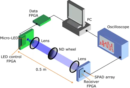
Figure 1: Schematic of the experimental setup.
The experimental arrangement is shown schemat-ically in Figure 1, and was operated in a dark
lab-oratory. The optical transmitter used is a single,
99×99µm2pixel from a 16×16 array chip of
micro-LEDs, emitting at 450 nm. The fabrication details and characterisation of similar devices are reported in reference [15]. The micro-LED array is bonded to CMOS control electronics, enabling individual control of the driving conditions for each pixel. This approach provides a mm-scale device containing optical emis-sion elements and control electronics. The device is housed on an evaluation printed circuit board (PCB) where a field-programmable gate array (FPGA) (Opal Kelly XEM3010) provides control signals and electri-cal power.
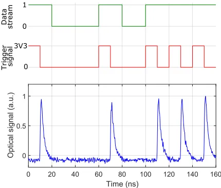
micro-LED, captured with an APD (Hamamatsu C5658) is shown in Figure 2, along with the data stream and trigger signals. The full width at half maximum of the optical pulse is 3 ns wide. In the following ex-periments, data rates of 50 and 100 Mb/s are used, resulting in RZ-OOK duty cycles of 15% and 30%,
and emitted average power of 1.62µW and 3.56µW,
respectively. The higher value at 100 Mb/s is a result of the pulse frequency being doubled, and the pulses not having time to fully relax back to no emission. There is a half bit period delay introduced by the falling edge triggering mechanism, however, this is easily accounted for during the decoding process.
0 20 40 60 80 100 120 140 160
Time (ns) 0
0.5 1
Optical signal (a.u.)
Data strea
m
Tri
gger
signal
0 1
[image:3.612.77.292.296.479.2]0 3V3
Figure 2: The 50 Mb/s binary data stream (upper), is converted to a suitable trigger signal for NRZ-OOK (middle), which produces optical emission from the
LED (lower).
For data transmission, the optical signal is colli-mated with a lens (Thorlabs C220TME-A) and trans-mitted over a lab bench distance of 0.5 m. A graded neutral density (ND) filter wheel (Thorlabs NDC-50C-4M-A) is used in the optical path to control the attenuation of the signal reaching the receiver. A collection lens (Thorlabs ACL4532U) focuses the light onto the active area of the optical receiver.
The SPAD array receiver consists of 64×64 SPADs
on a 21µm pitch, with a fill factor ofFf ill= 43% [9].
Including the surrounding electronics, the chip is 2.6×2.8 mm2, and packaged to interface with a PCB. A further FPGA (Opal Kelly XEM6310) provides con-trol signals and power to the chip, and an external 15 V bias is applied to the SPAD pixels. The individ-ual pixels have a photon detection probability (PDP)
of ηP DP = 26% at 450 nm [17], a measured dark
count rate of 350 Hz and a dead time of 20 ns. The output of the SPADs is combined using XOR trees and ripple counters so the device is operated as a digital silicon photomultiplier (dSiPM), with a single output of photon counts at a given sample rate [10,18].
For the experiments here, a 32×32 subset of the array
was set as active, in order to reduce the total dark count level while still enabling a large dynamic range. Additionally, an ND filter with 3% transmittance was placed infront of the active area to reduce background counts from stray light around the system.
The photon count signal from the chip is read out from low voltage differential signaling (LVDS) pads using a differential probe and oscilloscope. Using the FPGA interface, the array was set to output the number of received photons at a rate of 200 MHz,
with a range of 0-31 photon counts. The analog
voltage signal from the LVDS pads was captured by the oscilloscope, resampled and digitized to recover a photon count signal. To decode the bit stream, photon counts are integrated over the bit period and compared to a threshold value.
As the output from the receiver is a number of pho-tons at a given sample rate, the detected phopho-tons per second (Φdet) is readily obtained from the oscilloscope
trace. Incident photons per second (Φinc) can then
be calculated according to:
Φinc=
Φdet ηP DE(1−ΦdetτNd)
. (1)
Here, N is the number of active SPADs, τd is the
dead time of a single SPAD, andηP DE is the photon
detection efficiency of the array, given by ηP DE =
ηP DPFf ill. Incident optical powerPinc is then given by:
Pinc= ΦincEph, (2)
3
Results & Discussion
To asses the BER performance of the communication
link, the PRBS of 215bits was repeatedly transmitted
until over 106bits were received. Experiments were
performed at 50 and 100 Mb/s, for various incident power levels, producing the BER curves in Figure
3. A target BER threshold of 2×10⁻³ is plotted
for reference, as this is sufficient for forward error correction (FEC) codes to achieve an output BER
of 1×10⁻⁹ [19]. The signal properties at the FEC
threshold are summarized in Table 1. An incident optical power of 0.9 and 3.0 nW is required for 50 and 100 Mb/s respectively, corresponding to sensitivities of−60.5 and−55.2 dBm.
0 1 2 3 4 5
Incident optical power (nW) 10-6
10-4 10-2 100
BER
[image:4.612.317.522.231.512.2]50 Mb/s 100 Mb/s FEC threshold
Figure 3: BER against incident optical power incident on the receiver for data rates of 50 and 100 Mb/s.
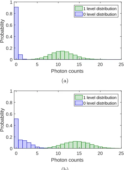
At 50 Mb/s with 450 nm photons and a target BER of 2×10⁻³, the attained sensitivity of the system is
11.1 dB away from the SQL of−71.6 dBm. The 26%
PDP and 43% fill factor accounts for 9.5 dB of the difference, with the remainder attributed to the effects of background and dark counts. This can be seen in Figure 4a, which shows the experimental probability distributions of photon counts for transmission of a binary “0” and “1” at the FEC threshold for 50 Mb/s. Both closely follow a Poisson distribution around their mean, and can be readily distinguished by applying a decision threshold to identify the transmitted bit. The
non-zero count levels for transmission of a “0” push the threshold requirements to higher levels, increasing the power requirements above the SQL. Nevertheless, an average of only 4.6 detected photons is required to achieve the FEC threshold. Accounting for PDP and fill factor with Equation 1, this corresponds to 41 incident photons per bit.
0 5 10 15 20 25
Photon counts 0
0.2 0.4 0.6 0.8 1
Probability
1 level distribution 0 level distribution
(a)
0 5 10 15 20 25
Photon counts 0
0.2 0.4 0.6 0.8 1
Probability
1 level distribution 0 level distribution
(b)
Figure 4: Probability distributions of 0 and 1 level photon counts per bit for (a) 50 and (b) 100 Mb/s at a BER of 1×10⁻³.
For 100 Mb/s, the attained sensitivity is 13.4 dB
from the SQL of−68.6 dBm. It would be expected to
[image:4.612.76.282.321.484.2]Table 1: Received optical power (P) at the FEC threshold for 50 and 100 Mb/s, with corresponding sensitivity
(S), distance to the SQL (D), average detected photons per bit (φdet) and average incident photons per bit
(φinc).
Rdata P S D φdet φinc
(Mb/s) (nW) (dBm) (dB) (ph/bit) (ph/bit)
50 0.9 -60.5 11.1 4.6 41
100 3.0 -55.2 13.42 7.5 68
Poisson distributions, associated with whether the previous transmitted bit was “0” or “1”. If the previ-ous bit is “1”, some photons from the LED pulse trail into the next bit, due to the longer tail of emission seen in Figure 2. This pushes the decision threshold to a higher level, increasing the requirement on incident power for distinguishing a “1” from a “0”. This is a limitation from the pulse performance of the micro-LED, and may be lifted with devices operating with shorter pulse widths. Despite this limitation, only 7.5 detected photons are required per bit to reach the FEC threshold, corresponding to 68 incident photons per bit.
Reference [11] provides a useful review of state-of-the-art high sensitivity SPAD receivers. The work presents an integrated SPAD receiver system with sen-sitivities of−51.2 and−46.3 dBm for 50 and 100 Mb/s with a BER of 2×10⁻³. Sensitivities of−46.2 and
−43.8 dBm for 150 and 200 Mb/s respectively are
shown for a higher BER of 6.5×10⁻³. In both cases a 635 nm laser with external modulator was used as the optical transmitter. Our work shows a sensitivity improvement of 14.3 and 11.4 dB respectively over the lower data rates at a wavelength of 450 nm, where the SQL is also higher due to the higher photon energy. While we are currently unable to reach data rates above 100 Mb/s due to limited FPGA output rates and micro-LED pulse widths, related work with the same receiver and a laser diode transmitter shows the same trend in sensitivity enhancement [9].
Both transmitter and receiver used here are mm-size, chip-scale devices housing LEDs, drive electron-ics, photodetector arrays and receiver electronics. The current system houses these chips in ceramic packages connected to evaluation PCBs, which are 13×18.5 cm2 and 12.5×20.5 cm2 for transmitter and receiver
re-spectively. While this hardware is already at a PCB level and relatively compact, many parts of the evalu-ation boards would be unused in a final applicevalu-ation, allowing transceiver systems to be developed on the scale of a few square centimeters.
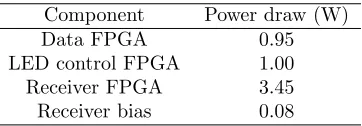
The electrical power for the system is drawn by four elements: the data FPGA, LED control FPGA, receiver FPGA and receiver bias. Power for the micro-LED emitter and CMOS control electronics is drawn through the LED control FPGA. The SPAD photode-tectors are powered through the additional receiver bias, while the surrounding electronics draw power through the receiver FPGA. The power consumption of the system is summarized in Table 2, with the total transmitter and receiver combined consuming 5.48 W. The current arrangement has not been optimised for power consumption, so this can be considered an up-per ceiling on the requirements. Power requirements can be readily reduced by streamlining the FPGA con-figurations, combining the data and control boards, and moving to application-specific integrated circuits (ASICs). Estimating from the CW performance of similar devices in reference [15], the micro-LED pixels show a low-current, wall-plug efficiency of around
1-2%. With an emitted optical power of 1.62µW, this
Table 2: Power consumption of components in the system, totalling 5.48 W.
Component Power draw (W)
Data FPGA 0.95
LED control FPGA 1.00
Receiver FPGA 3.45
Receiver bias 0.08
4
Conclusion
In conclusion, a communication link with data rates at 100 Mb/s has been demonstrated with a sensitivity
of−55.2 dBm, 13.42 dB from the SQL. This link was
achieved using a highly integrated transmitter and re-ceiver with low form factor control electronics. While the decoding was performed offline, utilising a high-speed oscilloscope, the digital nature of the system will enable full decoding using digital electronics in the future. Additionally, the receiver can operate at higher output frequencies and count ranges, however, the signal becomes increasingly analog, and the decod-ing method could not reliably convert the oscilloscope voltage trace back to integer photon counts. A future system which directly acquires a digital signal through the receiver FPGA will bypass the need for this con-version and greatly increase the dynamic range of the receiver. Furthermore, the CMOS controlled micro-LED arrays have been demonstrated for multi-level communications, which could exploit this enhanced dynamic range to enable higher data rates with only minor adjustments to FPGA configurations [16].
The small form factor, lack of complex hardware, simple transmission scheme and low power con-sumption enables high data rate, high sensitivity data communications on a low SWaP budget. An optimised version of the hardware used here could be employed in low SWaP applications, without strongly affecting payload capabilities or power systems.
The underlying data for this work is
avail-able at: http://dx.doi.org/10.15129/ fe315481-2a4a-4b84-a8ea-b239ddf27074
Funding Information
This work was funded by the UK Engineering and Physical Sciences Research Council (EPSRC) (EP/M01326X/1, EP/S001751/1)
References
[1] S. Rajbhandari, J. J. D. Mckendry, J. Herrnsdorf, H. Chun, G. Faulkner, H. Haas, I. M. Watson, D. O. Brien, and M. D. Dawson, “A review of Gallium Ni-tride LEDs for multi-gigabit-per-second visible light data communications,”Semiconductor Science and Technology, vol. 32, no. 2, pp. 1–44, 2017.
[2] H. Haas, L. Yin, Y. Wang, and C. Chen, “What is LiFi ?” Journal of Lightware Technology, vol. 34, no. 6, pp. 1533–1544, 2015.
[3] D. Chitnis, L. Zhang, H. Chun, S. Rajbhandari, G. Faulkner, D. O’Brien, and S. Collins, “A 200 Mb/s VLC demonstration with a SPAD based re-ceiver,”2015 IEEE Summer Topicals Meeting Series, SUM 2015, vol. 3, pp. 226–227, 2015.
[4] B. S. Robinson, D. O. Caplan, M. L. Stevens, R. J. Barron, E. A. Dauler, and S. A. Hamilton, “1.5-photons/bit Photon-Counting Optical Communica-tions Using Geiger-Mode Avalanche Photodiodes,”
LEOS Summer Topical Meetings, 2005.
[5] B. S. Robinson, A. J. Kerman, E. a. Dauler, R. J. Barron, D. O. Caplan, M. L. Stevens, J. J. Carney, S. a. Hamilton, J. K. W. Yang, and K. K. Berggren, “781 Mbit/s photon-counting optical communications
using a superconducting nanowire detector.”Optics Letters, vol. 31, no. 4, pp. 444–446, 2006.
[6] L. Zhang, D. Chitnis, H. Chun, S. Rajbhandari, G. Faulkner, D. C. O’Brien, and S. Collins, “A comparison of APD and SPAD based receivers
for visible light communications,” Journal of
Lightwave Technology, vol. 36, no. 12, pp. 1–1,
2018. [Online]. Available: http://ieeexplore.ieee.org/ document/8304770/
[7] O. Almer, D. Tsonev, N. A. Dutton, T. Al Abbas, S. Videv, S. Gnecchi, H. Haas, and R. K. Hender-son, “A SPAD-based visible light communications receiver employing higher order modulation,”2015 IEEE Global Communications Conference,
[8] S. Gnecchi, N. A. Dutton, L. Parmesan, B. R. Rae, S. Pellegrini, S. J. McLeod, L. A. Grant, and R. K. Henderson, “Analysis of Photon Detection Efficiency and Dynamic Range in SPAD based Visible Light Receivers,”Journal of Lightwave Technology, vol. 34, no. 11, pp. 2774–2781, 2016.
[9] J. Kosman, O. Almer, T. A. Abbas, N. Dutton, R. Walker, S. Videv, K. Moore, H. Haas, and R. K. Henderson, “A 500Mb/s -46.1dBm CMOS SPAD re-ceiver for laser diode visible-light communications,”
IEEE International Solid-State Circuits Conference (Accepted Oct 2018), 2019.
[10] S. Gnecchi, N. A. Dutton, L. Parmesan, B. R. Rae, S. Pellegrini, S. J. McLeod, L. A. Grant, and R. K. Henderson, “Digital Silicon Photomultipliers
With OR/XOR Pulse Combining Techniques,”IEEE
Transactions on Electron Devices, vol. 63, no. 3, pp. 1105–1110, 2016.
[11] B. Steindl, M. Hofbauer, K. Schneider-Hornstein, P. Brandl, and H. Zimmermann, “Single-Photon Avalanche Photodiode Based Fiber Optic Receiver for Up to 200 Mb/s,”IEEE Journal of Selected Topics in Quantum Electronics, vol. 24, no. 2, 2018.
[12] H. Zimmermann, B. Steindl, M. Hofbauer, and R. Enne, “Integrated fiber optical receiver reducing the gap to the quantum limit,” Scientific Reports, vol. 7, no. 1, p. 2652, 2017. [Online]. Available: https://doi.org/10.1038/s41598-017-02870-2
[13] W. Shieh and I. Djordjevic,OFDM for optical
com-munications. London: Elsevier, 2010.
[14] J. J. D. McKendry, B. R. Rae, Z. Gong,
K. R. Muir, B. Guilhabert, D. Massoubre,
E. Gu, D. Renshaw, M. D. Dawson, and R. K. Henderson, “Individually addressable AlInGaN micro-LED arrays with CMOS control and subnanosecond output pulses,”IEEE Photonics Technology Letters, vol. 21, no. 12, pp. 811–813, jun 2009. [Online]. Available: http://ieeexplore.ieee.org/lpdocs/epic03/ wrapper.htm?arnumber=4814576
[15] S. Zhang, S. Watson, J. J. D. McKendry,
D. Massoubre, A. Cogman, E. Gu, R. K. Henderson, A. E. Kelly, and M. D. Dawson, “1.5 Gbit/s multi-channel visible light communications using CMOS-controlled GaN-based LEDs,”Journal of Lightwave
Technology, vol. 31, no. 8, pp. 1211–1216, apr
2013. [Online]. Available: http://ieeexplore.ieee.org/ lpdocs/epic03/wrapper.htm?arnumber=6458971
[16] A. D. Griffiths, M. S. Islim, J. Herrnsdorf, J. J. D. McKendry, R. Henderson, H. Haas, and E. Gu, “CMOS-integrated GaN LED array for discrete power level stepping in visible light communications,” Op-tics Express, vol. 25, no. 8, pp. A338 – A345, 2017.
[17] J. A. Richardson, L. A. Grant, and R. K. Hender-son, “Low dark count single-photon avalanche diode structure compatible with standard nanometer scale CMOS technology,”IEEE Photonics Technology Let-ters, vol. 21, no. 14, pp. 1020–1022, 2009.
[18] T. A. Abbas, N. A. W. Dutton, O. Almer,
N. Finlayson, F. M. D. Rocca, and R. Henderson, “A CMOS SPAD Sensor with a Multi-Event Folded
Flash Time-to-Digital Converter for Ultra-fast Optical Transient Capture,”IEEE Sensors Journal, vol. 1748, no. c, pp. 1–1, 2018. [Online]. Available: http://ieeexplore.ieee.org/document/8283619/
[19] ITU, Geneva, Switzerland, “Recommendation