ADVANCED DIGITAL
MOLTI
SlAVE
Product Reference Manual
ADVANCED DIGITAL CORPORATION
USA OFFICE
5432 PRODUCTION DRIVE
HUNTINGTON BEACH. CA 92649
TELEPHONE: (714) 891...004
TELEX: 183210 ADVANCED HTBH
UNITED KINGDOM OFFICE
27 PRINCESS STREET
HANOVER SQUARE. LONDON W1 R8NQ
UNITED KINGDOM
409-0077 / 409-3351
MULTI SLAVE PRODUCT REFERENCE MANUAL
Revision A.O
Advanced Digital Corporation
5432 Production Drive
Huntington Beach, Cali£ornia
92649
USA
Telephone:
(714) 891-4004
Telex:
183210 ADVANCED
HTBH
Advanced Digitsl (U.K.> Ltd.
27
Princess Street
Hanover· Square
London, U.K.
Copyright
(C) 1985 by
Advanced Digital Corporation
5432 Production Drive
Huntington Beach, Cali£ornia
92649
All rights reserved.
No part o£ this publication may be
repro-duced,
transmitted,
stored in a retrieval system, or translated
into any
language or computer language,
in any £ora or by
any
means,
electronic,
mechanical,
magnetic,
optical,
che~ical,Dsnual,
or
otherwise,
without the prior written perMission
o£
Advanced Digital Corporation.
Multi Slave Product Reference Manual
NOTICES
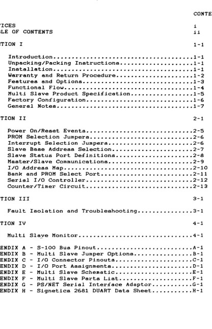
TABLE OF CONTENTS
SECTION I
CONTENTS
i
ii
1-1
Introduction •••••••••••••••••••••••••••••••••••••• 1-1
Unpacking/Packing Instructions ••••••••••••••••.••• 1-1
Installation •••••••••••••••••••••••••••.•••••••••• 1-1
Warranty and Return Procedure ••••••••••••••••••••• 1-2
Features end Options •••••••••••••••••••••••••••••• 1-3
Functional Flow ••••••••••••••••••••••••.••••••••••
1-4
Multi Slave Product Speci£ication •••••••••.••.•••• 1-5
Factory Con£iguration •••••••••••••••••••••••••.•••
1-6
General Notes •••••••••.••••.•••••••••.••.••••••••• 1-7
SECTION II
2-1
Power On/Reset Eventa ••••••••••••••••••.•.•••••••• 2-5
PROM Selection Jumpers .••••••••.••.••••••.••••••••
2-6
Interrupt Selection Jumpera ••••••••••••••••••••••. 2-6
Slave Sase Address Selection •••.••.••••.•••••••.••
2-7
Slave Status Port De£initions •••••.••••••••••••••• 2-8
MasterlSlave Communications •••••••.••••.••••••••••
2-9
110
Address Map ••••.••.•.•••••.•••.•••.•••••••.••• 2-10
Bank and PROM Select Port ••••.••••.••••.••••.••••• 2-11
Serial
110
Controller •••••••••••.••••.•.•••••.•••• 2-12
Counter/Timer Circuit •...••••..•••.•.•..•••••..•.• 2-13
SECTION III
3-1
Fault Isolation and Troubleshooting • . . . • . . . . • . . • . . 3-1
SECTION IV
4-1
Multi Slaye Monitor • . . • • • . • . • . . . • . . • • . . . • . . • . . .
4-1
APPENDIX A - S-100 Bus Pinout • • • . . • . . • . . . • • • . • . . . • • . . . • A-1
APPENDIX
B -
Multi Slave Jumper Options • • . . . • . • . . • . . • . .
B-l
APPENDIX C -
I/O Connector Pinouts • • . . • • • . . . • • . . . C-1
APPENDIX D -
110
Port Assignments . • • • . • • • . • . . . . • . • . . . • •
D-l
APPENDIX E -
Multi Slave Schematic • • . • • • . . . . • . . . • . . . • . • E-l
APPENDIX F -
Multi Slave Parts List • . • . • . . • . . . • • . . • . • • .
F-l
APPENDIX G -
PS/NET Serial Inter£ace Adaptor . . . • • . . . . G-1
APPENDIX
H -
Signetics
2681
DUART Data Sheet ..•.••••.•.
H-l
[image:4.620.97.514.62.708.2]Multi Slave Product Reference Manual
Illustrations:
Figure 1-1
Figure
1-2
Figure
2-1
Figure
2-2
Figure
2-3
Figure
2-4
Figure
2-5
Figure
2-6
Tables:
T8ble
2-1
Table
2-2
T8ble
2-3
Table
2-4
Multi Slave Block Diagrsn •••••.••.••••..•• 1-4
Multi Slave Component Layout •••••••••••.••
1-6
PROM Selection Ju.per.s . . • • . • • • . . • . . • • • • . • .
2-2
Interrupt Jumper Selection ••••..••••••.••.
2-2
Base Address Selection .••••••••••••.••.•••
2-3
Master Status Port De£initions .•••••••••••
2-4
Slave Status Port De£initions •.
a • • • • • • • • • •2-4
Bank and PROM Select Port .••••.•••••••••••
2-7
Master
5-100
Port Assignments •.•.•••.•••••
2-3
1/0
Port Assignments •••..•••••..••••.•••••
2-6
Bank Select Bit De£initions •••.•••••••••••
2-7
Serial
110
Cable Connector ••••••••••••••••
2-8
Multi Slave Product Reference Manual
Section 1
INTRODUCTION
This
Product Re£erence Manual provides information
to
install,
utilize
and maintain the Advanced Digital Corp.'s Multi Slave
S-100 bus compatible computer.
The Multi Slave is a single printed
circuit
board,
conforming to the IEEE-696 form factor
of
5.25
inches
by 10 inches (13.33 cm by 25.4 cm),
providing three
in-dependent
8
MHz
280
central processors,
each with two
64k
byte
banks
of
memory, two serial
110
ports, and a counter/tiger.
UNPACKING/PACKING INSTRUCTIONS
When the Multi Slave is delivered by a transfer
co~pany,i t must
be carefully inspected
for
damage.
Prior to accepting delivery,
carefully
inspect the shipping container for obvious damage.
If
damage
is evident,
note i t on the waybill and reqUire that
the
delivery
agent sign the waybill.
Notify the
transfer
company
immediately, and submit a damage report to the carrier.
Remove
the Multi Slave and any accessory items from the shipping
container.
Retain
the shipping container any packing
material
for
possible
reshipment.
Leave the Multi Slave in
i t s
anti-static envelope until installation time.
INSTALLATION
After
verifying that the intended enclosure for the Multi
Slave
will provide adequate power and air flow,
remove the Multi Slave
from
i t s anti-static envelope.
Inspect and
verify
that
the
configuration
Jumpers
on
the Multi Slave are correct
for
the
Multi
Slave's intended utilization.
Attach
I/O
cables
to
the
connectors provided for serial
1/0
dSrequired.
Insert the Multi
Slave
printed circuit board into a Buitable
5-100
bus slot
con-nector.
Multi Slave Product Reference Manual
Section
1
WARRANTY AND WARRANTY RETURN PROCEDURE
Advanced
Digital Corporation warrants that i t s products will
be
£ree from defects in material and workaanship £or a period of
360
days of shipment from the factory.
1£
a
customer
experiences a defect in
either
workManship
or
materials
during the warranty period,
noti£y your supplier
i .
-mediately.
Your supplier may repair the Multi Slave or deter.ine
i f some other action is'to be taken.
In the event that a return
o£ the Multi Slave is deemed neccessary, obtain a RETURN MATERIAL
AUTHORIZATION (RMA) NUMBER from your supplier.
original
supplier's
is
clearly
not
accept
number.
Repack
the
Multi Slave and any accessory iteas in the
packing
material and ship i t
in
accordance with your
shipping
instructions.
Make
sure the RMA
number
marked
on
the shipping label.
Your supplier will
delivery of a return shipment without the proper RMA
**********************.
*
WAR
N I N G
*
**********************.
The Multi Slave as delivered does not generate,
use,
or radiate
radio frequency energy.
However, after installation and
applica-tion
of power,
the Multi
Slave may generate,
use,
or
radiate
radio frequency energy.
Advanced Digital Corporation recoMaends
that the Multi Slave be installed in
an
enclosure which
complies
with
the provisions for computing devices pursuant to Subpart
J
of Part 15 o£ FCC rules, which are designed to provide reasonable
protection against such interference.
Multi Slave Product Reference Manual
Section 1
FEATURES AND OPTIONS
The Hulti Slave provides the following features:
a
Three
independent a-bit, a
MHz
280 Microprocessors
a
Each CPU
has 128k of memory,
configured as two
64k
byte banks, with a 1k to 16k area of
co~~on(shared)
memory.
a
Two
asynchronous
serial
110
ports per
CPU.
Level
conversion to
EIA
RS-232C or
RS-422
standards i&
provided via the PS/NET (paddle card) accessory.
o
Independent baud
rate selection on each serial port
o
Counter/TiBer
providing real tiBe clock
capability
o
User selectable PROM, Jumper configurable for one o£
the following: 2716, 2732, 2764, 27128, or 27256.
o
I££E-696 5-100 Bus Compatibility
o
Auto.atic power-on/reset bootstrap loader and
resi-dent monitor/debugger utility.
Multi Sleve Product Reference Manual
Section 1
...
...
A
....
..
~
rt
.--+
..
2681
+--fJ
DUARl
f4-..
po'....
..
----.
...
r--~
...
~
..
...
PROM
.1
Z80-H
CPU
~..
..
...
Bank
...
(1 of 3)
> - - -r---.
Control
64k
&
Timing
RAM
'
r
-~
L_---..
p,
.. I NTER-
S-100
FACE
....
BUS
"
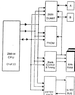
-Figura 1-1
Mult! Slave
Block
D1agraa
FUNCTIONAL FLOW
Figure
1-1
illustrates the maJor £unctionsl components
of
the
Multi Slave computer board.
Initially. immediately following the
power-on/reset
event,
a l l
three processors are held in a
reset
state.
Each
processor must be individually activated
by
e
net-work
master.
Once t.he master
has
activated
a
Multi Slave
pro-cessor~
the selected slave
CPU
then begins executing the
instruc-tions provided by the onboard
EPROM.
Depending upon user response
and intervention,
the proceenor will either initiate the
execu-tion of the resident Monitor/Debug program, or begin the download
request sequence to receive an operating system.
[image:10.626.192.449.90.411.2]Multi Slave Product Re£erence Manual
Section 1
HULTI SLAVE PRODUCT SPECIFICATIOH
Physical and Environmental:
For. Factor
Size
Weight
Temperature
operating
storage
Humidity
Altitude
Power Requrements:
Power Regulation
Cooling
IEEE-696 S-100 standard
5.25 inches
x
10.0 inches
x
.75 inchea
14 oz.
·0 to 50 degrees Ce1c1us
-65 to 150 degrees Celciua
o
to
95~,non-condensing
o
to 10,000 £eet (operating)
+5VDC
@
xx.x Amps (xx Watts)
On board, providing 4.75 to 5.25VDC
1-5 CFH <cubic £eet per
~inute)air £1ow
Power Supply Requirements:
Unregulated
Functional Speci£ication:
Processor
Memory
Processor Clock
Serial Controller
FACTORY CONFIGURATION
+ 7VDC Hin1JluJl
+11VDC Average
+25VDC HaximuD <peak)
+14.5VDC Minimum
+21.5VDC Average
+35.0VDC Maximum (peak)
-14.5VDC Minimum
-21.5VDC Average
-35.0VDC Maximum <peak)
2i10g 280H
128k Dynamic
RAM
8.000 MHz
Signe~ics
2681 DUART
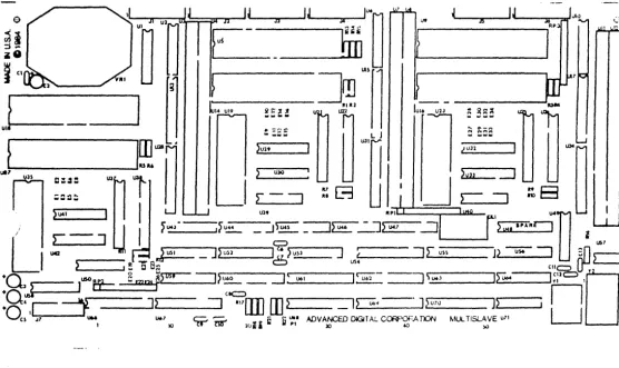
Hulti Slave Product Re£erence Manual
Section
!
Figure 2-2
Multi Slave COMpOnGnt Layout
The
£actory standard con£iguration o£ the MuJti Slave uses a 2764
EPROM,
end
does not
utili.ze
the 5-100 Vectored Interrupt Lines.
The base address of
the board is Jumpered
£01110
address 90H
at
Jumper block E-19 thru E-26 (lower left quadrant).
[image:12.624.28.584.196.527.2]Multi Slave Product Reference Hanual
Section 1
GENERAL NOTES
The Multi Slave contains three independent 2i109 280-H CPUs.
The
principal
110
device £or each processor is the
Signetics
2681
DUART
<Dual Universal Asynchronous Receiver/Transaitter).
This
particular device was cnosen £or its many i'eatures, which include
an internal duel baud rate generator and counter/tiaer.
Several types of PROMs are supported by the Hulti Slave, based
on
Jumper options.
The PROM types supported are a8 %ollowa:
2716,
2732, 2764, 27128
~nd27256.
PROM addressing begins at
OOOOH.
Each processor contains
a
total 0%
128k
o£ user available .eMory,
configured as two 64k banks, and is selectable through ao£tware.
There is only one interrupt source on the Multi Slave,
which i8
provided by the DUART.
Typically,
the 280
CPU will be operated
using Mode
1
interrupts (see the 2ilog
ZBO
Technical Hanual £or a
discussion o£ 280 interrupt modes>.
Each slave
i s
also capable o£ interrupting the master via the
S-100
vectored interrupt lines.
This will be discussed in detail
later.
Each 280 CPU is driven by a cent!al
8 MHz
oscillator;
the
three
DUARTs are driven
by
a COMmon
3.6864
MHz crystal.
Multi Slave Product Re£erence Manual
Section 2
POWER-ON/RESET EVENTS
Each Multi Slave CPU is held in a reset state until such t i . e
8S
the master enables the operation o£ a slave.
The master enables
a
slave
by issuing an output byte to the slave's
base
address
with
bit
D4
reset.
The PROM is
automatically
selected,
and
instruction execution begins at address OOOOH.
The
ADe supplied PROM initializes
bo~hchannels o£ the DUART
to
9600
baud, then tests channel
A
£or an available input character.
I£ a character is available, the Multi Slave monitor
i s
activated
which issues the £ollowing message to the terMinal on channel
A:
Multi Slave Monitor Version
1.x
Generated
HM-DD-YY
Copyright
ee)
1985
Advanced Digital Corporation
Enter
~?~£or HELP
A
complete discussion o£
the
Multi
Slave
~onitor ~aybe £ound in
section IV o£ this manual.
1£ an input character is not available at serial chennel A within
approximately
100
milliseconds,
the startup program will
enter
the
cold
boot process,
sending an
operating
system
download
request to the master processor over the S-100
bus.
Multi Sleve Product Re£erence Manuel
Section 2
PROK SELECTION JUMPERS
Each
CPU has a Jumper block to select the PROM
type.
£ollowing table to set these Jumpers.
Usa
the
E.
,-&
S4-IIP
ez.'7_?lf
1
0 02
PROM TYPE
JUMPER
3
0 04
---
---5
0 06
2716
(2K)
3-5,
4-6
7
0 08
2732
(4K)
5-7,
4-6
2764
(8K)
1-3, 5-7
TYPICAL JUMPER
27128 (16K)
1-3, 6-8,
5-7
[image:16.634.92.554.108.283.2] [image:16.634.132.536.384.534.2]BLOCK
27256
(32K)
1-2,
6-8,
5-7
Figure
2-1
Hulti Slave PROM Selection Ju.pera
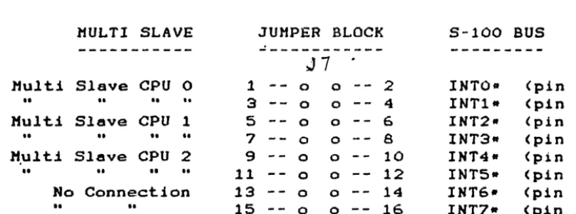
INTERRUPT SELECTION JUMPERS
Each Multi Slave CPU may interrupt the master processor on one of
two
5-100 vectored interrupt lines.
Selection o£ interrupts
1.
8S
£ollows:
MULTI SLAVE
JUMPER BLOCK
5-100
BUS
---
---
J7
---Multi Slave
CPU
0
1
0 02
INTO-
(pin 4)
I I I I
.. ..
3
0 0
4
INT1-
(pin
5)
Multi Slave
CPU
1
5
0 06
INT2-
(pin
6)
••
..
••
..
7
0 08
INT3-
<pin 7)
M.ulti Slave CPU
2
9
0 010
INT4-
(pin
8)
I I I I I I
..
11
0 0
12
INTS-
(pin
9)
No
Connection
13
0 014
INT6·
(pin
10)
••
..
15
0 016
INT7-
(pin
11)
Figure
2-2
Kulti Slave Interrupt 3uaper Selection
I£ the interrupt selection structure shown above is not suitable.,
wire
wrap connections between the Ju.per block pins
.8Y
be
used
in place o£ Jumper plugs
rthus allowing any given Multi Slave CPU
to use any
0%
the eight 5-100 vectored interrupt linea.
Multi Slave Product Reference Manual
Section 2
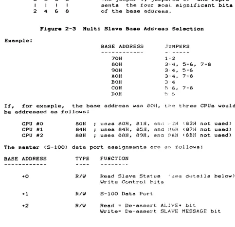
SLAVE BASE ADDRESS SELECTIOW
Each
Multi
Slave
CPU
occupies :four o£
the
r.aeterls
I/O
though
only
three are actually used
by
each CPU.
Base
selection
o:f
the Multi Slave board is as
£ollc;ovs:
ports,
address
t=J~- E'l.~
(7)(6)(5)(4)
1
3
5
7
a
0 0 0MSB
a
0a
a
I
I
I
2
4
6
8
LSB
AddreSB selection
Ufas
LOW TRUE LOGIC
Cno Jumper=l, Jumpcled=O)
and
repre-sents
the four
~oBLsigni£icant bita
of
the base address.
Figure 2-3 Hulti Slav. Baaa
Add~Od~Selection
Example:
BASE ADDRESS
JUMPERS
---
-
"_._---'JOH
1··2
80H
3-4, 5-6, 7-8
90H
3·
4,
5-6
AOH
8'''4,
7-8
BOH
3 ··4
COH
~~~"0,.
7-8
DOH
::.~ (:-.J
IE,
£or example,
the base
addresR
waR
BOIl,
Lhe
three CPUs would
be addressed as £ollowa:
CPU
#0
BOH
CPU
#1
84H
CPU
#2
88H
The
master <5-100) data
BASE
ADDRESS
TYPE
+0
R/W
+1
R/W
+2
R/W
uses
80H,
81H. on:::;
," :2H
~83Hnot used)
;
uses 84H,
85H,
nn(,jB6H
<87H
not used)
;
usee
BAH, B9H,
8.na
f.~AHcBSH
not used)
port assignments
ere
r.11.,
i 0110'..,.5:
FUNCTION
Read
Sl~ve St~tus i~ee d~tailsbelow)
Write Control bits
5-100
Datt! Port.
Read
=
De-assert
ALIVE-
bit
Write= De-sesert SLAVE MESSAGE bit
Table 2-1
Haater 5-100
Port
AaaigJ1M\snta
[image:17.623.57.540.253.720.2]Multi Slave Product Reference Manual
Section 2
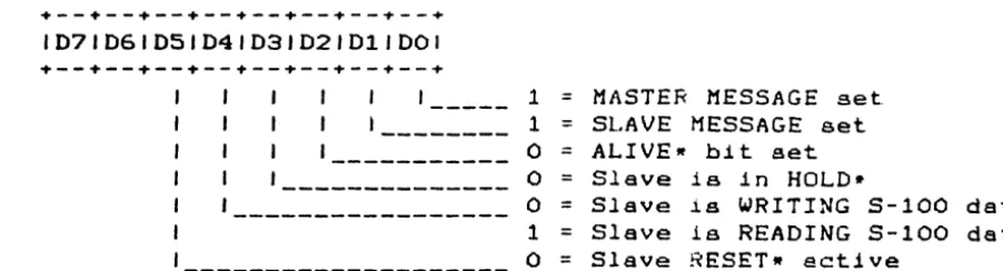
SLAVE STATUS PORT (read by Master Processor
.--.--.--+--.--+--.--.--+
1071061051041031021011001
.--+--+--+--+--+--+--+--+
1
=
MASTER MESSAGE
set
1
=
SLAVE MESSAGE
set
o
=
ALIVEw
bit set
o
Slave
i s
in
HOLD.
o
=
Slave
i s
WRITING
5-100 data
1
=
Slave
1s
REAOING
S-100 data
o
=
Slave
RESETw
active
STATUS PORT (written by Haster Processor)
+--+--+--+--+--+--+--+--+
1071061D5104J03102101JOOJ
+--+--+--+--+--+--+--+--.
1
=
set
MASTER MESSAGE
bit
1
=
reset slave processor
Figure 2-4
Haater
Statu. Port Bit Oa£intiona
Note that bits 06 and D7 of the STATUS PORT are not used, and are
on
(1) when the port is read by the Master Processor.
Note also
that there are four low active terms;
ALIVE.,
HOLD~,WRITE*,
and
RESET-.
[image:18.624.82.533.92.214.2]Multi Slave Product Re£erence Manual
'::;ect.
i
OTl:z
MASTER/SLAVE
COM~UNICAT!ONSFor
the master processor to send data to the
slRve,
the
sl~v~must be reading the 5-100 data port.
Conversly, £or the slave to
send
data to the master,
the slave must write to the 5-100 data
port be£ore the master reads i t .
As mentioned
ea1'li~r,when the
slave is reading or writing to the S-100 data port,
i t is placed
in
8HOLD (wait) condition,
and released to
resume
processing
when the Master Processor writes or reads the corresponding port.
This
ensures that the master and slave(s) remain in
synchroniza-tion
during
bus communication;
reliable network
operation
1s
achieved
when the other status bits
(ALIVE-,
READ/WRITE-,
and
HOLD-) are implemented as part o£ a communications protocol.
The
Haster Processor may reset a slave processor at any time
by
issuing
an output to the appropriate slave status port with
bit
D4
set.
To reactivate the slave, the master must again issue an
output
byte to the slave's status port with bit D4
reset,
£01-lowed by
a
short post-reset delay.
An
e~arnpleof
this
sequence
is shown below:
SL_RES:
LD
A,lOH
SET BIT D4
OUT
(SLVBASE),A
;
OUTPUT TO SLAVE BASE ADDRESS
LD
B,,16
;
LEAVE THE
BIT
SET
...
SL_R05:
DJNZ SL R05
. . .
FOR A SHORT TIME
)COR
NOT 10H
;
TURN OFF BIT D4
OUT
(SLVBASE),A
;
UN-RESET THE SLAVE
LD
B,16
.
,
SET UP FOR POST-RESET DELAY
SL_R10:
EX
(SP),HL
;
THIS IS
A
EX
(SP),HL
;
VERY EFFECTIVE
DJNZ SL R10
;
TIME
WASTER
RET
;
RETURN TO CALLER
The
suggested
handshake mechanism between the master and
slave
is as £ollows (£or transmission £rom slave to master):
the slave
f i r s t asserts the SLAVE MESSAGE bit.
The master t,ay see this by
polling
(reading the slave status pbrt),
or
the Multi Slave may
be
configured to cause an interrupt on the
master.
In
either
case, once the SLAVE MESSAGE bit has been asserted, the slave CPU
then
outputs i t s £irst data byte to the S-100
bus
communications
port.
Upon doing so, the slave CPU is £orced into a wait
condi-tion,
which
the
master must veri£y by testing the
WRITE-
and
HOLD~
bits at the slave status port.
Once the master has
deter-mined
that
both signals are true,
i t may then
read
the
byte
waiting at the S-100 data port.
The elave is
rel~asedto resume
processing,
£ree to continue sending subsequent data bytes, etc.
In
a
MASTER
Upon
master to slave transmission,
the master must SBsert
th8
bit,
which the slave sees by polling
i t s '
status
port.
detecting
the active MASTER bit,
the elave must reset
it
Multi Slave Product Re£erence Manual
Section 2
(indicating
to the master that the slave is ready
to accept
the
message),
and
immediately issue a read to the 5-100 data
port.
Again, the slave processor is £orced into a wait condition. which
the aaster must veri£y by testing the
READ and HOLD- bits at
the
slave status port.
Once the master has determined that both
sig-nals
are
active,
i t Day then write the data byte to the
5-100
data port.
The slave is released to resume processing,
£ree to
continue receiving subsequent data bytes, etc.
The £ollowing page provides a brie£ example o£ this
master/slave
dialogue:
Multi Slave Product Re£erence Manual
Section 2
MASTER PROCESSOR (RECEIVING MESSAGE FROM SLAVE)
IN
BIT
RET
OUT
WAIT1:
IN
BIT
JR
BIT
JR
IN
RET
A, (SLVSTAT)
SLVMSG,A
NZ
(MSGRST),A
A, (SLVSTAT)
SLVWRT,A
NZ,WAITl
SLVHLD,A
NZ,WAITl
A, (SLVDATA)
; GET SLAVE STATUS
; IS SLAVE MESSAGE BIT SET?
; NO, RESUME OTHER TASKS (ACTIVE LOW)
OUTPUT CLEARS SLAVE MESSAGE BIT
; (CONTENTS OF A-REG INSIGNIFICANT)
GET SLAVE STATUS BITS
IS SLAVE WRITING TO
5-100
PORT?
LOOP IF NOT
; IS SLAVE IN A HOLD CONDITION?
LOOP IF NOT
; ALL IS READY - GET THE DATA BYTE
; AND RETURN TO
CA~LINGTASK
MASTER PROCESSOR (SENDING MESSAGE TO SLAVE>
LD
OUT
WAIT2:
IN
BIT
JR
WAIT3:
IN
BIT
JR
BIT
JR
LD
OUT
RET
A,OOOOOOlOB
(SLVSTAT),A
A, (SLVSTAT)
MASTER,A
NZ,WAIT2
A,
(SLVSTAT)
SLVWRT,A
Z,WAIT3
SLVHLD,A
NZ,WAIT3
A,(HL)
(SLVDATA),A
SET MASTER MESSAGE BIT . . .
••. SO THE SLAVE WILL SEE IT
GET SLAVE STATUS
HAS THE SLAVE RESET IT YET?
LOOP UNTIL HE HAS DONE SO
GET SLAVE STATUS AGAIN
IS SLAVE READING THE
5-100
PORT?
LOOP IF NOT
IS SLAVE IN A HOLD CONDITION?
; LOOP IF NOT
GET BYTE
TO
SEND
SEND IT
TO
THE SLAVE
AND RETURN TO CALLING TASK
SLAVE PROCESSOR (RECEIVING MESSAGE FROM MASTER)
IN
IN
RET
A, (HASTER)
A, (DATAPORT)
; CLEAR MASTER MESSAGE BIT
AND IMMEDIATELY READ THE S-100 PORT
; RETURN TO CALLING TASK
SLAVE PROCESSOR (SENDING MESSAGE TO MASTER)
IN
A, (SLVMSG)
LD
A,B
OUT
(DATAPORT),A
RET
; SET SLAVE MESSAGE BIT
B-REG HAS DATA BYTE TO SEND
; OUTPUT DATA BYTE
TO 5-100
DATA PORT
; RETURN TO CALLING TASK
Note that these examples transmit and receive only a single
byte
at
a
ti~eand provide only a skeletal communications
protocol.
The slave may utilize the 280 block input and output instructiona
to receive and
trana~itany number o£ bytes to the master, though
the
user
should employ a slightly more
sophisticated
protocol
when
doing so.
In typical networking environments,
the
£iret
byte
transmitted contains the length o£ the message
to
£ollow,
Implementation of such networking schemes i8 l e i t to the user.
Multi Slave Product Re£erence Manual
Section 2
BOOTSTRAP SOFTWARE
The
£ollowing
program
will provide the user with
a
bootstrap
£8cility
which £ollows the protocol set £orth in the prior
sec-tion.
This program is identical to that contained
in
the
Multi
Slave monitor
PROM
rand assumes that an intermediate loader
will
be received £rom the master.
SLVMSG
SALIVE
SDATA
SHl1EH
BOOT:
IN
IN
LD
OUT
LD
INIR
JP
EQU
EQU
EQU
EQU
20H
60H
0070H
BOOOH
Ar(SLVMSG)
Ar (SALIVE)
BCrSDATA
(C) rB
HLrSHMEM
SHHEM
; 110
READ SETS SLAVE MESSAGE BIT
110
READ SETS SLAVE ALIVE BIT
; B=HESSAGE LENGTH
rC=PORT ADDRESS
; ONLY ADDRESSES ABOVE BOOOH ARE
; ACCESSABLE WHILE PROM IS ENABLED
; SET SLAVE MESSAGE BIT
; SET SLAVE ALIVE BIT
; B=BYTE COUNT (0=256 BYTES)
; C=PORT ADDRESS
SEND BYTE COUNT FIRST
; ADDRESS TO STORE INCOMING MESSAGE
(WHICH WILL BE THE INTERMEDIATE
; LOADER PROGRAM)
RECEIVE ENTIRE MESSAGE FROM MASTER
BRANCH
&
EXECUTE INTERMEDIATE LOADER
Multi Slave Product Re£erence Manual
Section
2
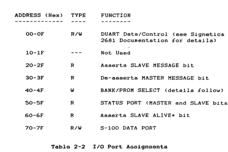
110 ADDRESS HAP
Each Multi Slave CPU has an identical I/O address map.
assignDents are as £ollowa:
ADDRESS (Hex)
TYPE
FUNCTION
The port
OO-OF
R/W
DUART Data/Control (see Signetics
2681
Docu~entation£or details)
10-lF
Not Used
20-2F
R
Asserts SLAVE MESSAGE bit
30-3F
R
De-asserts MASTER MESSAGE bit
40-4F
w
BANK/PROM SELECT (details £ollow)
50-SF
R
STATUS PORT (MASTER and SLAVE bits)
60-6F
R
Asserts SLAVE ALIVER bit
70-7F
R/W
S-100 DATA PORT
Table 2-2
110 Port Aaaignaonta
The
user should be aware that although i t would appear that
the
5-100 data ports would collide with one another, they are
actual-ly physicalactual-ly separated in the hardware.
This is explained a bit
more clearly by the £ollowing diagram:
SLAVE PROCESSOR NUMBER
MASTER PROCESSOR
#0
I/O ADDRESS 70H •••.••••••••.••.•..• I/0 BASE ADDRESS
+0
#1
1/0
ADDRESS 70H ••••••••••••.••..••• I/0 BASE ADDRESS
+
4
#2
1/0
ADDRESS
70H • • • • • • • • • • • • • • • • • • • • I / 0
BASE ADDRESS
+8
SLAVE STATUS PORT (read by the Slave, read only>
+ - - + - - + - - + - - + - - + - - + - - + - - +
1071061051041D31021011001
+ - - + - - + - - + - - + - - + - - + - - + - - +
1--- 1
=
MASTER message active
--- 1
=
SLAVE message active
Figure 2-5
SlavQ Status Port Bit Definitions
[image:23.624.103.547.128.424.2]Multi Slave Product Ref'erence Manual"
Section
2
BANK AND PROM SELECT PORT
The
BANK/PROM SELECT port apeci£iea which of' the two 64k
memory
banks
is
to
be
active,
and whether or not the
PROM
is
to
be
selected.
The bit de£initions £or this port ere as f'ollows:
? - - ? - - ? - - ? - - ? - - ? - - ? - - ? - - +
1071061051041031021011001
1
=
Select Bank
0
1
=
Select Bank
1
o
=
PROM
on,
1
=
PROM
o££
not used, ignored
high order four bits
select amount o£ shared
memory (in Kbytes),
de£ined in Table
2-3
Figure 2-6
Bank and Prom Seloct Port Bit
D~£inition.Bits D4-07
Shared
Hex Value
Amount
---
---0
16k
1
15k
2
14k
3
13k
4
12k
5
11k
6
10k
7
9k
8
8lt
9
7k
A
6k
B
5k
C
4k
D
3k
E
2k
F
lk
Table 2-3
Bank Select Bit
De£initionA
NOTE:
Bank
0
and 1 are mutually exclusive and must not be
set
active at the same time.
When the
PROM
is selected, only memory
locations
BOOOH through
OFFFFH
may be accessed £or
RAM
read
and
write operations.
[image:24.617.59.532.91.607.2] [image:24.617.203.360.367.604.2]Multi SIeve Product Reference Menuel
Section
2
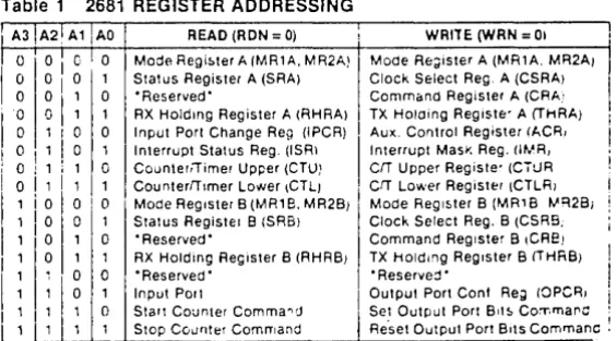
SERIAL 1/0 CONTROLLER
The Multi SIeve provides two independent aerial
IIO
channels
per
CPU,
both contained in one seriel
1/0
controller,
tho Signetica
2681
Dual Aaynchronoua Receiver/Transmitter (DUART).
The
DUART
containa two internal,
independent baud rate generators, capable
o£ producing
18
user selectable baud rates.
Level conversion
to
EIA
RS-232
or RS-422 level is provided by an
external
circuit
aa •••
bly called the PS-NET.
SERIAL CHANNEL CONNECTORS
Connectors for each serial liD channel are located aerOS8 the top
o£
the
Multi Slave board (see figure
1-1
£or exact
place.ent).
Each connector has the following pinout:
PIN
NO.
SIGNAL NAME
DIRECTION
---
---
---1
DCD
Data Carrior Detect
input
2
DSR
Data Set Ready
input
•
3
•••
see note below
input/output
4
RXD
Receive Data
input
3
CTS
Clear to Send
input
6
TXD
Transtlit Data
output
7
RTS
Request to Send
output
8
DTR
Data Terminal Ready
output
9
CLK
Tx/Rx
Clock
input/output
10
GND
Signal Ground
ground
11
N1C
12
+16
VDC
supply voltage
13
-16
VDC
supply voltage
14
+5
VDC
supply voltage
•
On
channel
A,
this term is RNG (ring detect)
and
may
be
connected to the ring detect line on a Dodea.
This line has
no
connected on channel
B.
Tabla
2-4
Serial 110 Cable Connector
Multi Slave Product Re£erence Manual
Section 2
COUNTER/TIMER CIRCUIT
The counter/timer circuit is contained on the
DUART
device.
As
i t s
name implies,
i t may be used as a timer (programmable
divi-der) or a counter,
providing an appropriate indication when
the
specified countdown value has reached zero.
I t should be noted that unlike the
280 eTC,
the
DUART's
counter/-timer
uses a 15-bit countdown register,
providing much
greater
£lexibility in i t s application.
Appendix
H
contains the data sheet £or the Signetics 2681 device.
Hulti Slave Product Re£erence Manual
Section 3
FAULT ISOLATION
Fault
isolation
is the process o£ identifying a fault
and
the
resultant cause
of
the £ault to the lowest possible level.
This
section
deals
with hardware fault isolation
and
is
generally
independent o£ so£tware considerations.
Prior to any attempt at fault isolation,
a test environment must
be validated.
Generally, the test environment. will consist o£ an
5-100 chassis,
motherboard,
power supply,
S-100 extender card,
snd
a known good Multi Slave.
Validation consists o£
removing
all
other 5-100 circuit cards from the chaSSiS,
and
any
other
devices loading the +8, +16, and/or -16 VDC power supplies.
Having
removed all circuit boards from the
motherboard,
verify
that
the £ollowing voltages referenced to ground (5-100 bus
pin
50 and 100) are within the tolerances listed below:
S-100
PIN
DEFINITION
MINIMUM
AVERAGE
MAXIMUM
---
---
---
---
---1
+
8
VDC
+7.0
+11 .0
+25.0
51
+ 8 VDC
... 7.0
"'11.0
... 25.0
2
+16 VDC
+14.5
+21.5
+35.0
52
-16 VDC
-35.0
-21.5
-14.5
The
above conditions must be met before proceeding with the next
teat..
Step 1:
Visual
V~rificdtionInspect
the
suspect Multi Slave to verify that
components
correctly
installed and properly seated in their sockets.
ponents
may be compared against a known good Multi
Slave.
DIP components have
t.he
Bame pin 1 orient.ation.
Step 2:
On Board
+5
VDC Regulation
are
Com-All
Remove
power from the motherboard.
Insert the
S-100
extender
card
into
a
suitable slat in the motherboard,
then insert
the
Multi
Slave
into the extender card
Bocket.
Apply
power
and
measure the voltage at Ul-16.
This voltage must be between 4.75
and
5.25 VDC.
Step 3:
Clock
Veri£jcat~anVeri£y the clock £requenciea at the £ollow1ng locations:
U57-7
80ns
U49-8
150ns
FAULT ISOLATION
central clock
distr~butedto all
CPU"s.
central SIO clock
distr~butedto
all DUART's.
Multi Slave Product Re£erence Manual
Section 3
Step
5:
Veri£y
pin 19
Step
6:
Memory Veri£ication
memory row and column addressing by monitoring pin
1
on each AM2965 memory driver circuit.
Monitor Veri£ication
and
Data Set Ready
(Jl-2,
J3-2, J5-2)
MUST be low for the monitor to
issue a message to the console.
Verify that the PS/NET-1 card
ie
properly
con£igured and connected to the Multi Slave,
and
that
the
terminal's baud rate is set to 9600.
Ensure that the
Mul~iSlave
card
ia in a reset-hold condition by pressing the
system
reset button on the computer's front panel.
Then, using a
moni-tor program on the Master Processor,
activate the desired
slave
CPU by issuing an OUT <slave command port),40H.
The Multi Slave
monitor
should issue i t s logon message as described in Section
2
of
this manual.
Press
any key on the slave console within
two
seconds a:fter "un-resetting" i t .
The Multi Slave monitor should
then
be
ready to accept
"::.~("Jmmands.STEP 7:
Ve r
i
fit.:
dt.i () n
0f
0t 1) e
l'M a
J
0r
Co
m po n e n t s
Verification
of
other maJor Multi Slave components requires
de-velopment
of
short software routines which will
provide
scope
Inops to support Lhe analysis of Multi Slave signals some of the
more
commonly
required routines have been incorporated
in
the
Multi Slave Monitor program.
These tests include memory and
I/O
.read
and wr
1
te
loops.
See
t.he moni
tor
command l I s t :for
:further
informatiofJ.
o
q)(
Multi Slave Product Reference Manual
Section 4
THE MULTI SLAVE MONITOR
The Multi Slave contains a very powerful monitor program,
provid-ing numerous features not found
in
moat simple monitors.
Some
of
the highlights include:
o
Full %unction decimal/hexadecimal calculator
(expression evaluator)
a
280
disassembler
o
Off"set variable :for
LIST
and DUMP functions
a
Comprehensive memory
diagnoat~ceo
Printer echo
(all console input & output
may be
echoed to the printer) with user selectable baud
rate
o
Scope loops - memory and
1/0
readlwrite loops
The basic
mo~itorcommand structure
15as follows:
COMMAND LETTER [VI r,V2 (,V3JJJ
<CR>
where Vl, V2, and V3 are var1ables (command parameters), and
unless
~ndicatedotherwise,
are
hexadec~malvalues.
mayor may not
be
requ~reddepending upon the command.
ALL
commands
are
termInated by a
carriage
return
fields
wi~hinbrackets
( [ l )are
optional.
Parameters
Note that
<CR>,
and
B
D Xl [X2JJ
MULTI
SLAVE MONITOR
MONITOR COMMANDS
BOOT
this
slave system by
issuing
an
op-erat~ng
system download request to the
mas-ter.
For
specific details about the
down-load reques
t
pr ... )gram,
see "Master /Slave
Com-mun.i.cat lons"
.In
sect.~onI I
o:f
this manual.
COMPARE
~hecontents o£ memory,
starting at
address
Xl to address
X2,
£or
X3 bytes. If a
mismatch occurs, the contents
o:f
both
addres-ses
will
be
displayed.
DUMP
the
contents o£
memory
beginning
at
address
OOOOH
<i£ the
DUMP
command has
not
been previously
~nvaked),or contInue at the
last address plus one,
or
at address Xl
for
256
bytes (or thru address X2).
SEE
OFFSET
(S)
COMMAND.
Multi Slave Product Re£erence Manual
Sect~on4
F Xl,X2,X3
G
Xl
H
I
Xl
}{ [N1J
L
rx.!
rX2J
1
11 X1,X2,)(3
a
X1,X2
P
(rll)
S Xl
T
LXl
r,X211
FILL
memory
from address
Xl
thru
X2
with data
value
X3.
GO to address
Xl
(via a
CALL)
and
exec~tethe
instructions at that address.
See
the next subsection
for
details
of
command.
tholS
INPUT
data
from
I/O
port address
Xl
and
d.1s-play
1~on
the console.
To display the
con-tents
of the next sequential port,
enter
a
carriage
return:
to
display the contents
of
the
prlor
port,
enter
a
minus (-) sign.
D1 st.,} ay
t
he cur
k 811tbank number, or
swi tch
t.o
bauk Nt.
l.IST,
using 280
mnemonics,
the .lnstructions
beginning
at
address
OOOOH
(i£
the
LIST
co~Jnand
has not been
previously
invoked),
or
'_:lJnLinue at
t,he
last
address
pluB one,
or
at
ddrlr~ss
Xl for 18
lInea
of
instructione,
or
t.hr u
addr
c·gSX2.
SEE OFFSET
(:$)COMMAND.
MOVE
tta~contents
of memory beginning
at
ad-dr
€ .. f.~p.. X:~t.hl'
LJ addr·t,~8E'.X2
to
address
X3.
OUTPUT data byte X2 to I/O port address Xl.
Toggle the
PRINTER
online
Dr
offline,
or set
t
tle
p:r
1n
t.
~r
b
a
\jd
1·a
t
~t
LIval u
e
D 1
(
dec 1
mal ) .
::':;ET
the.
~:unt.:~lItRof
tlddrE-'flBXl.
The current
• .: ',.:> n t.
f?,n
t!-!.
l ) (t.
hem
€.-m
0 l'Y 1
0cat
.l 0n
W 1l I b
e
dis
-played.
Enter
<CR> to
advance
to the
next
.a •..
1
d
1" ~~!? S , ( - )t o g
( lb
d ek
t
CJthe
p r
1or address,
t
w (.;.
h
~>=
~dec
i mal
c
h a (" a
c:
t.
t?r
s
(
0 - 9 ,
A - F )
t
0',:: h:s 1"1 9
02t
h
8h
t::' Xval u e ,
(,)
1 ( ,A) t
0c
han g e t
h e
c··
(:II Jt .
~n t ..•.
l
(.1A:) C T
T
val
1Ie A .
TEST mt:!muty tJeglllnlng at OOOOH thru the
h~gh t~~.tposS.l.ble
address tt.hp-
s t a r t i n g address of
the
mt"Jn
L
t_Ol·-1),
01"st.al· t
ing
at
add1' eSBXl
(tll:l·U
addret:.t,f'.
XL').
A plus
sign
(-t-)will
be
~isplayed
With
each
Buccess£ul
pass.
Any
ad-ell-ee,s
'..."hleh fai
18
will be
displayed
at
the
console,
along
wlth the
e~pectedand
£a.111ng
data
pattern.
Upon
completion of
the
test
(one
complete
pass
at all
specli.led
addree-ceo),
the test will be termlnated and a
mes-sage
will
be d.lBplayed
at the coneole.
~ulti
Slave Product Re£erence Manual
Section 4
Z
Xl,.X2
(,.X3l
S (Xl]
Perform a Scope Loop test specified by
func-tion
Xl,.
as follows:
o
=
Memory Read Loop
1
=
Memory Write Loop
2
=
110 Read Loop
3
=
110 Write Loop
Field
X2
is the memory address or 110
port
address,. and
X3
is the data value to be
writ-ten
to the specified memory or 110
address.
Note
that field
X3
is required only
i f
the
test function is a write operation.
Display the current offset value,
or
change
i t to value
Xl.
This offset will be added to
the
address
specified in the DUMP and
LIST
commands.
MONITOR ASPECTS AND CONSIDERATIONS
The
Multi
Slave monitor takes two important factors
into
con-sideration;
self preservation,
and the pOssibility of an active
master processor on the 5-100 bus during monitor execution.
Self
preservation implies the protection of the memory region in which
the monitor resides.
Interrupts are enabled while the monitor is executing; the
inter-rupt service routine performs one important tasK, that of setting
the
SLAVE ALIVE bit at each 16.666 ms interrupt interval.
This
ensures
that the master processor will not attempt to reset
the
slave; the slave always appears to be "alive."
Any command which modifies the contents o£ memory performs a test
of the target address to ensure that i t
i8
not
1)
the 280 Mode 1
interrupt
vector address or any portion of
i t
(i.e.
locations
0038H, 0039H
or 003AH), and 2) an address within the monitor.
In
case
1,
the SET,.
TEST,
FILL and
MOVE
commands will simply skip
over these locations.
In case 2, an error message will be issued
to the console.
There
are
two
1/0
address groups which muet be
accessed
with
care.
The f i r s t group is 20H thru 2FH; an
1/0
read in this range
asserts the SLAVE MESSAGE bit, indicating to the master processor
that the slave is requesting service.
Typically, this will
i n i t
-iate the operating system download sequence.
The
second 110 address group is 70H thru 7FH,
the "gateway"
to
the 5-100 bus.
An
1/0
read or write in this range causes the CPU
to enter a
WAIT
condition,.
terminated only a£ter the master
has
read
from or written to the corresponding
communications
port.
In most cases, this will be £atal to the monitor.
Multi Slave Product Reference Manual
Section 4
To prevent an inadvertent read or write to these ports, the
moni-tor will prompt with:
CONFIRM (YIN):
when
i t encounters
a read or write request to anyone
of
the
a£orementioned addresses.
A
single keystroke reply is required,
either
'y'
to perform the requested function, or any other key to
terminate i t .
OTHER FEATURES AND FACILITIES
The
Hulti
Slave monitor provides
a
means of obtaining
hardcopy
output
o£
all console 1/0.
When hardcopy
output
is
desired,
execution
of the 'P' command will display the
'PRINTER ON'
mes-sage at the console, with all subsequent console
110
being echoed
to the printer. The next invokation o£ the
'P'
command terminates
the printer output, and displays the
'PRINTER OFF'
message to the
console.
The
default printer baud rate is
9600
baud;
by using the second form of the
'P'
command:
Pn
<CR>
this may be changed
where
'n' is the desired baud rate.
The baud
rates
currently
supported are
50,
75,
110,
134.5,
150,
300, 600, 1200, 1800,
2000,
2400,
4800,
7200, 9600, 19,200
and
38,400.
There is one
special
case
here,
the
134.5
baud rate;
this value should
be
entered as
134
(without the decimal fraction).
All
monitor
commands may be terminated with the
ESC(ape)
key.
Console
(and
printer)
output may be temporarily
suspended
by
entering control-S
(~S)and resumed by entering control-C
(~O).A
monitor
command line may be 'deleted' by
entering
control-X
(AX).
This
causes the cursor to return to the beginning o£ the
current line, immediately to the right o£ the asterisk
(w)
proDpt
character.
I f
hardcopy output is enabled, a carriage returnlline
feed/space
sequence
is issued to the printer so that
the
next
command line is not typed over the current line.
All other control characters are invalid.
The monitor will issue
the bell character to the console in place o£ the control
charac-ter.
All lower case characters entered on the console are converted to
upper case.
Multi Slave Product Re£erence Manual
Section 4
THE 'H' COMMAND - EXPRESSION
EVALUATOR
Pocket calculators with such capabilities as hexadecimal
display
and
Boolean £unctione are a convenient tool,
but when one isn1t
handy,
such calculations
by
hand are tedious at best.
For
this
reason,
an
expression evaluator haa been included in the
Multi
Slave monitor program.
The expression evaluator has a total of
17
operators, as £ollows:
&
Dyadic AND
*
Dyadic MULTIPLY
+
Dyadic ADD or monadic
PLUS
Dyadic SUBTRACT
or monadic MINUS
I
Dyadic DIVIDE (twols complement)
I I
Dyadic REMAINDER
<
Dyadic LESS THAN
>
Dyadic GREATER
THAN
<=
Dyadic LESS THAN OR EQUAL
--
Dyadic
EQUAL
) =