Macdonald, Malcolm and Anderson, Pamela and Warren, Carl (2012) A
novel design concept for space-based polar remote sensing. In: SPIE
Remote Sensing Conference 2012, 2012-09-24 - 2012-09-27. ,
This version is available at
https://strathprints.strath.ac.uk/40979/
Strathprints is designed to allow users to access the research output of the University of Strathclyde. Unless otherwise explicitly stated on the manuscript, Copyright © and Moral Rights for the papers on this site are retained by the individual authors and/or other copyright owners. Please check the manuscript for details of any other licences that may have been applied. You may not engage in further distribution of the material for any profitmaking activities or any commercial gain. You may freely distribute both the url (https://strathprints.strath.ac.uk/) and the content of this paper for research or private study, educational, or not-for-profit purposes without prior permission or charge.
Any correspondence concerning this service should be sent to the Strathprints administrator:
The Strathprints institutional repository (https://strathprints.strath.ac.uk) is a digital archive of University of Strathclyde research outputs. It has been developed to disseminate open access research outputs, expose data about those outputs, and enable the
A novel design concept for space-based polar remote sensing
Malcolm Macdonald
a,*, Pamela Anderson
a& Carl Warren
ba
Advanced Space Concepts Laboratory, Mechanical & Aerospace Engineering, University of Strathclyde, Glasgow G1 1XQ, Scotland
b
Earth Observation Missions Group, Astrium Ltd., Gunnels Wood Road, Stevenage, Hertfordshire, SG1 2AS, UK.
ABSTRACT
Space-based remote sensing of the Earth is conducted from a fleet of spacecraft in two basic orbital positions, near-polar low-Earth orbits and geosynchronous orbits, with each offering its own advantages and disadvantages. Low-Earth orbits provide high-resolution observations at the expense of large-scale contextual information, while geosynchronous orbits provide near-global, continuous coverage at reduced resolutions. However, due to the rapidly decreasing horizontal resolution data-products derived from geosynchronous orbits are of degraded value beyond approximately 55 degrees of latitude. A novel mission design is introduced to enable continuous observation of all longitudes at latitudes between 55 and 90 degrees with an observation zenith angle of less than 60 degrees, without the use of composite images. A single Soyuz launch is used to deliver three spacecraft to 12-hr, highly eccentric true-polar orbits with apogee at 40170 km and electric propulsion is used to maintain the orbit apse-line coincident with the Earth’s poles. It is shown that the science payload mass can be traded against the mission duration, with a payload mass varying between 120 – 90 kg for mission durations between 3 – 5 years, respectively. It is further shown that the payload would have approximately of 2kW of power available during operations as the electric propulsion system is not operated at these times. Whilst the payload mass is less than a typical remote sensing platform in geosynchronous orbit it is considered that the concept would offer an excellent technology demonstrator mission for operational missions, whilst also enabling unique and valuable science.
Keywords: Polar, Remote Sensing, Taranis, Electric Propulsion, Mission Design, System Design, Mission Concept
1.
INTRODUCTION
The first weather satellite, TIROS-1, was launched in 1960 by the NASA,1 and rapidly demonstrated the value of space-based observations to assist weather forecasters. Today’s dependence of meteorologists, and in particular medium term (five to 30-days) weather forecasts on space-derived data is exquisitely illustrated by the European Centre for Medium-range Weather Forecasts (ECMWF) attempt to compare the relative value of spacecraft and conventional data sources in such forecasts. To allow the comparison to be conducted, the ECMWF found it was necessary to add Atmospheric Motion Vectors (AMV), a space-derived data product, to the ‘conventional-data’ in order to get any kind of basic medium-range forecast against which the benefit of adding other space-derived data could then be assessed.2
Space-based remote sensing is vital for global weather forecasting, ranging from nowcasting (< 6-hrs) through medium to longer term forecasts, climatic trend analysis, prediction of extreme climatic events, water resource analysis and management, natural disaster recovery and much more. Data users and service providers are progressively requiring an increasingly wide coverage, consistency and quality of product from space-based assets, whilst also seeking to maximize the temporal resolution at minimum data latency. A fleet of satellites owned by seven countries and regions (Europe is counted as a single region in this tally) monitor the Earth’s weather on a routine basis from two basic orbital positions; near-polar low-Earth orbits (LEOs) of about 800 – 900 km altitude and geosynchronous orbits (GEOs) at approximately 36 000 km above the Earth.
Considering the orbits currently in use for space-based remote sensing of the Earth, each orbit offers its own advantages and disadvantages. Polar orbiting LEO Sun-synchronous platforms in at least 3 orbit planes are required to provide high-resolution observations, but do so at the expense of large-scale contextual information. Additionally, at least six GEO platforms are required to provide meteorological products with near-global continuous coverage offering rapid-scan operations, feature tracking and atmospheric motion vectors. Note that each GEO platforms remains fixed above a given longitude, providing continuous observation of that region. However, the use of GEO platforms for space-derived products is critically limited due to the rapidly decreasing horizontal resolution and increasingly oblique viewing angle with increasing latitude, meaning that many derived products are not available beyond 55 degrees of latitude.3
*
2.
POLAR OBSERVATION
The inadequacy in polar spatial and temporal remote sensing significantly impacts many data products, including for example AMV retrieval, radiation budget analysis and estimation of bi-directional reflectance distribution functions (BRDF). To some extent the impact of this shortfall can be mitigated through the use of composite images.4,5 However, even with such a mitigation strategy it has been shown that in, for example, AMV retrieval, which is so key to medium-range forecasts, a ‘ring’ of missing observations occurs between approximately 50 and 70 degrees, depending on the required temporal resolution.6 This remaining data deficit is of huge importance as the polar jet stream, which is vital to, amongst other things the weather in the neighboring frigid and temperate regions, will typically be located in this latitudinal band. Furthermore, the generation of composite images adds to the data latency. As such, the breadth and depth of climate and meteorological data available for the tropics and mid-latitudes must be approximated by composite or mosaic images beyond approximately 55 degrees latitude, creating a data deficit over the critical polar-regions due to restricted spatio-temporal sampling. Continuous high temporal resolution meteorological observations will improve polar and neighboring temperate zone weather nowcasting as well as medium and far term forecasts. A comprehensive polar observing system will also allow improved monitoring of Essential Climate Variables (ECVs) to enhance understanding of climate change modeling. Furthermore, as the Polar Regions are undergoing rapid environmental change this, in the Artic in-particular, is creating new commercial opportunities that in-turn produce new environment pressures. A comprehensive polar observing system would enable monitoring of these actives and their impact. Summer ice melt is also creating new pressures on existing infrastructure, and the Northwest Passage is becoming ever more accessible as a shipping route, which will in-turn lead to a further general increase in economic activity and a potentially significant growth in surface, air and marine traffic. As such the current commercial Earth Observation market demand will spread to the poles, where currently it cannot be fully serviced.
3.
MISSION REQUIREMENTS
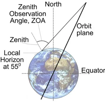
It has been noted that data products derived from observations made on GEO platforms begin to break-down at approximately 55 degrees latitude, by which time the observation zenith angle (OZA) is tending towards 60 degrees. It therefore follows that any future high-altitude polar observation platform should be able to observe between 55 and 90 degrees latitude with a ZOA of less than 60 degrees. Furthermore, to avoid the generation of composite images and to maximize the equivalence to GEO derived products it should be possible for a single platform to observe the entire target region.
Requirement,
A spacecraft shall be able to continuously observe all longitudes at latitudes between 55 and 90 degrees with an observation zenith angle of less than 60 degrees.
To complement the current space-based remote sensing architecture of the global observing system it is highly desirable that any future high-altitude polar observation platform be of a similar altitude to GEO.
Requirement,
The orbit apogee altitude shall be less than 45 000 km.
The ideal solution to overcome the identified polar remote sensing spatial and temporal data deficit would be a platform that remains fixed above the polar zenith at a distance similar to that of a GEO platform. No natural orbit exists to provide such an ideal solution, however the concept of a spacecraft ‘hovering’ stationery over the poles of the Earth is often termed a ‘statite’ or ‘PoleSitter’, and such an orbit is called a highly non-Keplerian orbit.7 A highly non-Keplerian orbit uses a continuous thrust vector to enable artificial equilibrium points in the three-body problem, as such a 1000 kg ‘statite’ or ‘PoleSitter’ spacecraft can be located approximately two to three-million kilometers above the poles of the Earth using a continuous thrust of order 150 – 200 mN, or at approximately GEO distance using a continuous thrust of approximately 300 N.
4.
GLOBAL CONTEXT
high latitudes including the polar ice shelf”, and recommending operational implementation of visible (VIS) and infrared (IR) imagers in order to monitor high-latitude phenomena related to winds, clouds, volcanic ash plumes, sea ice, snow cover, vegetation properties and wild fires with sufficient temporal resolution.8
HEOs have long been used for polar communications and high-latitude reconnaissance by the Soviet Union as ‘apogee-dwell’ means that such spacecraft are high in the northern sky, and virtually stationery. In particular, Molniya orbits, which have an inclination 63.4 degrees, the ‘critical inclination’, to provide zero secular rate of change of the argument of perigee, were first used in April 1965 by the Soviet Union and formed the basis for the first national satellite TV network in 1967 within the Soviet Union. HEOs, of which Molniya orbits are a subset, were apparently first proposed for Earth Observation in 1990,9 and are again attractive due to the long period of ‘apogee-dwell’. However, due to the perceived complexity of the observational geometry created by the varying altitude and velocity, the demanding spacecraft/imager pointing accuracy, and the risk associated with the harsh radiation environment such orbits have not yet been embraced for civilian remote sensing application.
Within the context of the WMO vision of the GOS in 2025, the Canadian Space Agency commenced study of a Polar Communication and Weather mission (PCW) to place two spacecraft onto HEOs over the northern hemisphere to provide remote sensing and communication products. Similarly, the Russian Federation began study of the multi-functional space system “Arktika”, which would consist of several spacecraft including those on Molniya orbits.10 It should be noted that whilst the PCW mission is largely based on an orbit at the critical inclination of 63.4 degrees, some consideration has been given to making minor deviations from this inclination.10,11
4.1.
Polar Viewing Geometry from a Molniya Orbit
Through careful consideration of the orbit perturbation force due to a non-spherical central body, it is noted that the induced secular variation of the argument of periapsis is inclination dependent. Using orbit averaging techniques, the change in argument of periapsis over one revolution can be written as,
cos (1)
Seeking zero secular variation of the argument of periapsis, Equation (1) is solved equal to zero; found when
[image:4.595.207.384.480.654.2]cos . Resultantly, the critical inclination is determined as (90±26.6) degrees. Thus, to the order of , all Earth orbits inclined at these values show no rotation of the apsidal line, irrespective of the values of semi-major axis or eccentricity. The inclination of a Molniya orbit is defined by the ‘critical inclination’.
Figure 1 shows the viewing geometry to all longitudes from apogee on a Molniya orbit to 55 degrees latitude, equivalent to the nominal upper latitude observation limit from GEO. The peak ZOA is approximately 70 deg., i.e. observing ‘over’
the pole; 10 deg. higher than when the same location is observed from GEO. As such, despite the merits of a Molniya orbit for remote-sensing it does not provide a complete solution to the problem of viewing frigid and neighboring temperate regions as no single platform can provide hemispheric-like observations that can be married up to GEO observations. As a result, polar observations, unlike equatorial observations, will remain dependent upon composite images that will be discontinuous in viewing geometry and in time. To provide continuous observation to all longitudes at latitudes between 55 and 90 degrees, with an observation zenith angle of less than 60 degrees with composite images, three spacecraft on Molniya orbits in three separate orbit planes, requiring three separate spacecraft launches, are required.
5.
TARANIS ORBITS
Recent research has shown that entirely new subsets of orbits are enabled through the application of near-term or current low-thrust propulsion technologies, and furthermore that these new orbits offer scientifically and commercially high-value remote sensing opportunities.12–15
Through the application of low-thrust propulsion technology the deficiencies of Molniya orbits for observing the key Polar Regions can be overcome by modifying the geopotential effects that define the critical-inclination and dictate the Molniya orbit plane shown in Figure 1. Using low-thrust propulsion to modify the effect of these perturbations the critical-inclination can be re-defined as a function of the spacecraft thrust magnitude. This extension of the Molniya ( meaning ‘lightning’) orbit to re-define the critical inclination using low-thrust propulsion is termed a Taranis orbit; Taranis is the Celtic God of Thunder.15
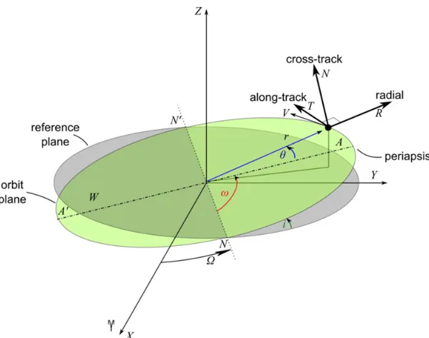
Using locally optimal control laws a near-optimal thrusting profile in the spacecraft ‘RTN’ axis, see Figure 2, can be defined.15,16 The simplest form of this thrusting profile restricts thrust to within the orbit plane and directs equal thrust along the radial, R, and along-track, T, directions. However, it is found that the required thrust magnitudes can be reduced by approximately 3 % by allowing the radial and along-track thrust magnitudes to have different, but still constant, magnitudes.15 It should also be noted that if the control profile is fully optimized, that is the thrust vector is no longer restricted to within the orbit plane and the thrust magnitude along each of the RTN axis is allowed to vary freely, then the required propellant mass can be reduced by approximately 3 – 4 %. Whilst such a fuel mass saving is clearly desirable the increased complexity of the thrust profile would require a significantly more complex spacecraft platform capable of thrust vectoring and throttling such that the instrument suite could maintain nadir pointing. Assuming that thrusting is restricted to within the orbit plane, and that equal and constant thrust is directed along the radial, R, and along-track, T, directions the required acceleration per direction from the propulsion system for a 12-hr Taranis orbit over a range of orbit inclinations is shown in Figure 3; as expected the required acceleration equals zero at the two critical inclinations.
A more detailed technical discussion, along with the full derivation of Taranis orbits can be found in [13 – 15].
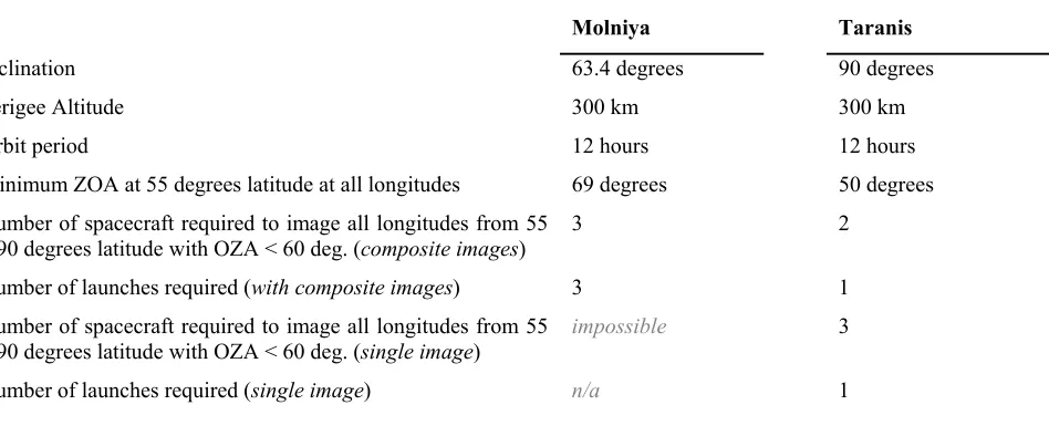
Using a 12-hr period Taranis orbit, at orbit inclination 90-degrees, it is found that only two spacecraft, in this single orbit plane, are required to provide continuous visibility with composite images to all longitudes at latitudes between 55 and 90 degrees, with an OZA of less than 60 degrees. Critically the use of a single orbit plane significantly reduces the constellation deployment costs, enabling the constellation to be launched on-board a single launch vehicle rather than in multiple launches. The addition of a third spacecraft in the same orbit plane enables continuous visibility without the use of composite images of all longitudes at latitudes between 55 and 90 degrees with an OZA of less than 60 degrees; providing observation opportunities of at least equal quality to a GEO platform and from a similar altitude. Such continuous visibility without the use of composite images cannot be achieved from a Molniya orbit. The third platform also offers graceful degradation to the constellation; as such Taranis orbits offer significant advantages over Molniya orbits in observation quality, operations cost and complexity, and the cost of deploying and maintaining a complete GOS. Table 1 summarizes the comparison between a 12-hour Molniya and a 12-hr, 90-degree Taranis orbits.
6.
MISSION ANALYSIS
Three principle difficulties have historically been recognized when considering the use of HEOs for remote sensing, the perceived complexity of the observational geometry created by the varying altitude and velocity, the demanding spacecraft/imager pointing accuracy, and
Figure 2 Spacecraft co-ordinate system, including spacecraft centered ‘RTN’ axis.
Figure 3 Required acceleration from an on-board propulsions system along each of the radial, R, and along-track, T, axis for a 12-hr Taranis orbit over a range of orbit inclinations.
[image:6.595.163.438.355.547.2]Table 1 Comparison of Molniya and Taranis orbits
Molniya Taranis
Inclination 63.4 degrees 90 degrees
Perigee Altitude 300 km 300 km
Orbit period 12 hours 12 hours
Minimum ZOA at 55 degrees latitude at all longitudes 69 degrees 50 degrees
Number of spacecraft required to image all longitudes from 55 – 90 degrees latitude with OZA < 60 deg. (composite images)
3 2
Number of launches required (with composite images) 3 1
Number of spacecraft required to image all longitudes from 55 – 90 degrees latitude with OZA < 60 deg. (single image)
impossible 3
Number of launches required (single image) n/a 1
6.1.
Radiation Environment
Any HEO, such as a Molniya or Taranis orbit, will cross the high energy (E >100 keV) trapped electron and proton populations twice per orbit; the so-called Van Allen radiation belts. However, it is noted that the period of apogee-dwell, and hence science operations, is in a relatively benign environment beyond the Van Allen belts, and further noting that electronics is intrinsically radiation ‘harder’ when turned-off the principle radiation risk is to the platform and not the instruments which should be off where possible during transits of the Van Allen belts.
Although the spacecraft experiences effects from both electrons and protons, the main threat comes from high-energy protons. Thus, in order to minimize the effects of radiation, the mission design should consider the impact of avoiding the region containing protons with energy E > 10 MeV. It is found that the flux of such high-energy proton drops below 10 particles per cubic centimeter per second at an altitude of 15 000 km. Hence, to avoid a high density of such energetic protons, and reduce the risk of damage to the spacecraft, the impact of making the orbit semi-latus rectum altitude greater than 15 000km should be considered.
6.2.
Orbit Analysis
The orbit design trade space is shown in Figure 4 to mitigate against the space environment effects and in Figure 5 to minimize the number of spacecraft, where space environment effects are not mitigated. Within Figure 4 the most beneficial orbit occurs at the intersection of the apogee altitude and semi-latus rectum limits, corresponding to an orbit period of 16.6-hrs. However, in order to provide an integer number of revolutions in an integer number of sidereal days, such that the ground-track will repeat in a relatively short time, the orbit period is reduced to 16-hrs; giving a repeat ground track in two days. Thereafter, the most suitable perigee altitude can be selected as the maximum possible without requiring an increase in the number of spacecraft to five, hence maximizing the mitigation of the space environment effects. It is concluded the best orbit to mitigate the effect of the HEO environment on the spacecraft has a perigee of 10000 km and an orbit period of 16-hrs, giving an apogee altitude of 41740 km.
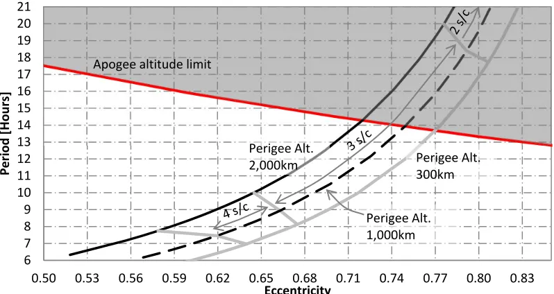
The analysis around Figure 4 is repeated within Figure 5 without the semi-latus rectum limitation. It is seen that orbits of period 9 or 12-hours are possible within the three-spacecraft zone. It is found that the 9-hour orbit requires a significant amount of propellant simply to maintain the orbit against atmospheric drag effects. As such, it is concluded the 12-hour orbit with a 300 km altitude perigee, giving an apogee of 40170 km, gives the best orbit when seeking to minimize the number of spacecraft required.
recovery orbits to regain the desired orbit alignment with the poles. In option A where four spacecraft are used, on a 16-hr orbit, the minimum such coast arc, occurring at beginning-of-life (BoL), is required to be of duration 4-16-hrs; equating to a true anomaly range of ±18.1 degrees about apogee. Similarly in option B where three spacecraft are used, on a 12-hr orbit period, the minimum such coast arc is also required to be of duration 4-hrs; equating to a true anomaly range of ±13.7 degrees about apogee. Should a greater level of thrust be available due to, for example, reduction in propellant mass, the coast arc can simply be extended to maintain a constant cumulative thrust over a single orbit from beginning-of-life to end-beginning-of-life.
Figure 4 Orbit design trade space to mitigate harsh HEO space environment.
Figure 5 Orbit design trade space to minimize number of spacecraft. 13 14 15 16 17 18 19 20 21 22 23
0.41 0.44 0.47 0.50 0.53 0.56 0.59
P e ri o d [h o u rs ] Eccentricity
Perigee Alt. 8000 km Perigee Alt.
11000 km
Semi latus rectum limit Perigee Alt.
10000 km Apogee altitude limit
6 7 8 9 10 11 12 13 14 15 16 17 18 19 20 21
0.50 0.53 0.56 0.59 0.62 0.65 0.68 0.71 0.74 0.77 0.80 0.83
P e ri o d [H o u rs ] Eccentricity Perigee Alt.
2,000km Perigee Alt. 300km Apogee altitude limit
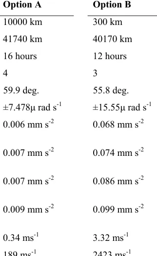
[image:8.595.98.497.441.653.2]Table 2 Summary of mission architecture options
Option A Option B
Perigee Altitude 10000 km 300 km
Apogee Altitude 41740 km 40170 km
Orbit Period 16 hours 12 hours
Required number of spacecraft (no composite images) 4 3
Actual maximum ZOA at 55 degrees latitude at all longitudes 59.9 deg. 55.8 deg.
Change in observation target angular velocity ±7.478 rad s-1 ±15.55 rad s-1
Acceleration Magnitude per R & T direction (continuous thrusting)
0.006 mm s-2 0.068 mm s-2
Acceleration Magnitude per R & T direction (no thrusting = 270 – 90deg.)
0.007 mm s-2 0.074 mm s-2
Acceleration Magnitude per R & T direction (minimum BoLcoast arc about apogee)
0.007 mm s-2 0.086 mm s-2
Acceleration Magnitude per R & T direction
(minimum BoLcoast arc about apogee & no thrusting = 270 – 90deg.)
0.009 mm s-2 0.099 mm s-2
Impulsive v (per orbit) 0.34 ms-1 3.32 ms-1
Impulsive v (per Julian year) 189 ms-1 2423 ms-1
Noting that the thrusters mounted on the radial direction, R, switch on/off at true anomaly 270 / 90 degrees and the thrusters mounted on the along-track direction, T, switch on/off at true anomaly 0 / 180 degrees the cumulative thrust time at BoL can be determined. For option B, it is found that the time from 270 – 90 degrees is approximately 0.9-hrs, whilst the time from 90 – 270 degrees is approximately 11.1-hrs, which with a 4-hr coast-arc about apogee reduces to 7.1-hrs of operation per orbit for the thrusters mounted on the radial direction. Similarly, the time from 0 – 180 degrees is half of the orbit period, 6-hrs, which with a 4-hr coast-arc about apogee reduces to 4-hrs of operation per orbit for the thrusters mounted on the along-track direction. Due to the fast transit of perigee, from 270 – 90 degrees, Table 2 also presents the required acceleration to allow coast-arcs at apogee and at perigee, from 270 – 90 degrees. Such a coast-arc at perigee would remove the need for a thruster to be mounted on the nadir facing side of the spacecraft and remove instrument visibility and exhaust contamination concerns.
6.3.
Soyuz Launch from Guiana Space Centre
Table 3 Summary of system mass allocations per mission architecture option
Option A Option B
Estimated Soyuz Launch Mass Capability 2442 kg 2983 kg
Available Launch Mass with 20 % / 10 % margin 1954 kg / 2198 kg 2386 kg / 2685 kg
Total Wet Mass Allocation per Spacecraft 488 kg / 550 kg 795 kg / 895 kg
Thrust Magnitude per R & T direction (continuous thrusting)
2.9 mN / 3.3 mN 54.1 mN / 60.9 mN
Thrust Magnitude per R & T direction (no thrusting = 270 – 90deg.)
3.4 mN / 3.9 mN 58.8 mN / 66.2 mN
Thrust Magnitude per R & T direction (minimum BoL coast arc about apogee)
3.6 mN / 4.0 mN 69.2 mN / 77.9 mN
Thrust Magnitude per R & T direction (minimum BoLcoast arc about apogee & no thrusting = 270 – 90deg.)
4.4 mN / 5.0 mN 78.7 mN / 87.7 mN
7.
SYSTEM ANALYSIS
Analysis of option A and B, in a 5-year mission, reveals that as expected a significant reduction in the trapped proton dose is gained by the higher perigee altitude of option A. However, consideration of the total ionizing dose (TID) shows that both options come within the applicable range of ‘Space Qualified’ parts when provided with 2 – 6 mm of shielding. Indeed, it is also noted that at around 2 – 4 mm of aluminum shielding the TID is similar or less than that of an equivalent geostationary platform. As such the penalty of an additional spacecraft to mitigate the space environment is considered excessive at this stage, and it is surmised that option B will provide the lower total cost architecture despite the likely increase in per spacecraft cost. Option A is hence not further considered.
It is apparent that the most-preferred design option is that of a minimum BoL coast-arc about apogee, with no thrusting through perigee, that is, = 270 – 90deg.
7.1.
Electric Propulsion System
The mass of the solar electric propulsion, SEP, system, , can be estimated as a function of the peak power demand of the SEP system as,
(2)
where, is the specific performance of the SEP and power sub-system. The peak power demand of the SEP system can be estimated as,
(3)
where, is the constant thrust required, is the efficiency of the SEP system and is standard gravity. Furthermore, the mass of the propellant tanks is estimated as 10 % of the propellant mass,
(4)
and the associated structure mass to support the tank can be estimated as,
The QinetiQ T6 thruster at full power, 4.5 kW, can provide 143 mN at specific impulse 4120 seconds and an efficiency of 64 %; moreover the specific impulse can be increased to almost 4300 seconds at an efficiency of 66 % by optimizing the neutralizer flow rate.19 However, assuming a specific performance of this would require a SEP system mass of approximately 250 kg, or over 30 % of the total wet mass allocation per spacecraft in option B. It is hence clear that the peak power demand from the SEP system must be reduced from this level. To reduce the peak power demand the demanded thrust level from the electric propulsion system should be minimised. However, reducing the thrust level from the optimal design point also results in a reduction in both specific impulse and efficiency, meaning that additional propellant would be required.19
Considering instead the Astrium RIT-XT thruster it is found that this has an optimal design point at a lower thrust level of around 100 mN and can thrust at 78 mN (corresponding to the most-preferred design option) with a peak power draw of approximately 2.4 kW and a specific impulse of order 4600 seconds. However, it should be noted that by increasing the thrust to 100 mN, with a peak power draw of approximately 3.2 kW, the specific impulse can be increased to approximately 4750 seconds. Again assuming a specific performance of this would require a SEP and power sub-system mass of approximately 264 – 352 kg; recall that two thrusters are required to operate simultaneously. It is seen that the increase in SEP and power sub-system mass (~90 kg), to gain the maximum specific impulse is quite significant and will most likely be greater than the reduction in propellant mass. As such the SEP system is sized for the most-preferred design option, i.e. minimum BoL coast-arc about apogee, with no thrusting through perigee, that is, = 270 – 90deg.
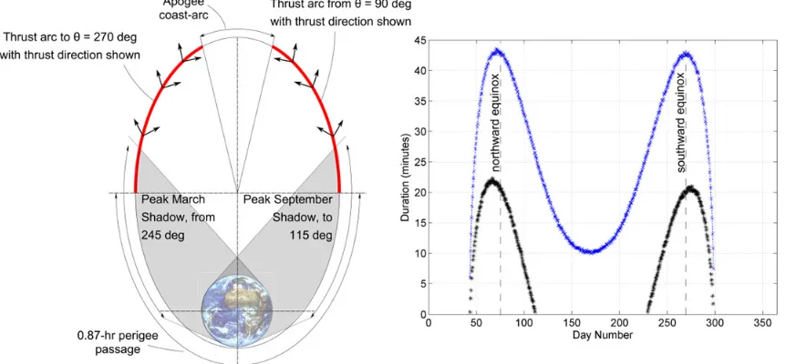
[image:11.595.83.514.449.649.2]The thrusters mounted on the positive radial direction, +R, i.e. spacecraft zenith pointing, operate between true anomaly 90 degrees and the apogee coast arc, and then following the coast arc until true anomaly 270 degrees; recall no thrusting is performed in the negative radial direction, i.e. towards nadir. And, the thrusters mounted on the positive along-track direction, +T, thrust between true anomaly 90 deg. degrees and the apogee coast arc, whilst thrusters mounted on the negative along-track direction, -T, thrust from the end of the apogee coast-arc to true anomaly 270 degrees. This is illustrated in Figure 6. The cumulative thrust time for the thrusters mounted on the positive radial direction is 7.1-hrs per orbit at BoL, whilst the cumulative thrust time of each of the along-track thrusters is 3.56-hrs per orbit at BoL. Hence, assuming an upper mission design duration of 5-years and a constant length apogee coast-arc it can be estimated that the radial thruster will be required to operate for approximately 26045-hrs, while the along-track thrusters will be required to operate for approximately 13005-hrs each; recall that the coast-arc length will increase as the spacecraft mass reduces due to propellant consumption, as such these cumulative thrust durations are overestimates. The Astrium RIT-XT thrusters have a design life of 15000-hrs (at 150 mN), hence, neglecting redundancy requirements, two thrusters will be required on the positive radial direction, while only one thruster will be required on each of the along-track directions.
Figure 6 shows the shadow duration through the Gregorian year along with the required time that the thrusters are on whilst the spacecraft is in shadow. It is seen that the peak thrust duration in shadow is 22-minutes; as such the perigee coast arc reduces the required power storage of the secondary batteries from 1.76kW-hrs to 0.88 kW-hrs. It should also be noted that to further reduce the required secondary battery size the apogee coast arc could be reduced or the nominal thrust could be increased and the perigee coast arc lengthened.
7.2.
Payload Mass Allocation
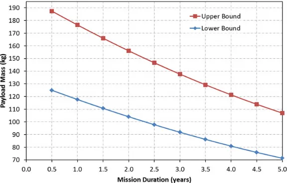
Using the above estimated SEP and power sub-system mass, a system-level mass allocation budget can be developed using the total wet mass allocation per spacecraft defined in Table 3; again assuming a total launch mass margin of 20 %. It is found that approximately 62 – 40 kg of propellant is required per year of mission operations; 62.3 kg in year one; 56.6 kg in year two; 51.0 kg in year three, and so forth. The reduction in propellant use per year is due to the increase in coast arc length from 13.7 degrees at BoL to 26.0 degrees after 5-years. Accounting for the SEP system mass, tank and support structure mass and propellant mass, the science payload mass can be estimated as 20 – 30% of the remaining spacecraft mass20 and is illustrated in Figure 7.
8.
CONCLUSIONS
[image:12.595.155.443.451.635.2]It has been shown that three spacecraft launched together on a Soyuz, using currently available technology, can provide continuous observation of all longitudes at latitudes between 55 and 90 degrees with an observation zenith angle of less than 60 degrees without the use of composite images. The payload mass can be traded against mission duration and a payload of order 100-kg can likely be operated for between 3 – 5 years, and a 150 kg payload for perhaps as much as 2.5-years. The use of a Soyuz launch vehicle is the principle restricting factor on the available science payload mass allocation. It is noted that the payload will be power-rich, as the approximately 2.4 kW of power required by the electric propulsion system when thrusting will be available to the payload during science operations as the electric propulsion system is not thrusting at this time. Furthermore, the use of a Taranis orbit for remote sensing is intended as a complement to the use of geostationary orbits for remote sensing, it is hence of note that geostationary missions, such as Chollian (also known as Communication, Ocean and Meteorological Satellite 1, COMS-1) with a mass of 2460 kg and a seven year design life, typically use an Ariane 5 launch vehicle, which costs significantly more than a Soyuz. It can thus be concluded that the novel design concept for space-based polar remote sensing presented in this paper would serve as an excellent technology demonstrator mission for such operational missions, resolving and demonstrate solution of the difficulties that have historically been recognized when considering the use of highly-elliptical orbits for remote sensing, whilst also enabling unique and valuable science.
9.
ACKNOWLEDGEMENTS
The authors acknowledge and thank Hugh Pumphrey and Chris Merchant, both of the School of Geosciences at the University of Edinburgh, for discussions over the science applications of a Taranis orbit.
REFERENCES
[1] Allison, L., J., Arking, A., Bandeen, W., R., Shenk, W. E., Wexler, R., “Meteorological satellite accomplishments,” Reviews of Geophysics, Vol. 13, No. 3, pp. 737-746 (1975); also NASA technical report NASA-TM-X-70782. [2] Norris, P., [Weather Satellites, Watching Earth from Space], Springer Praxis, Chichester UK (2010), pp23-44. [3] Riishojgaard, L.P., “Report on Molniya Orbits,” World Meteorological Organization Commission for Basic Systems, OPAG on Integrated Observing Systems Expert Team on Observational Data Requirements and Redesign of the Global Observing System, CBS/OPAG-IOS/ODRRGOS-7/Doc. 7.5, Seventh Session, Geneva, Switzerland, 12-16 July (2004). [4] Lazzara, M.A., Stearns, C.R.; Staude, J.A., Knuth, S.L., “10 years of Antarctic composite images,” 7th Conference on Polar Meteorology and Oceanography, and Joint Symposium on High-latitude Climate Variations, Hyannis, MA, Paper 9.4 (2003).
[5] Lazzara, M.A., Keller, L.M., Strearns, C.R., Thom, J.E.,Wieder, G.A., “Antarctic Satellite Meteorology: Applications for Weather Forecasting,” Monthly Weather Review, Vol. 131, pp 371 – 383 (2003).
[6] Lazzara, M.A., et al., “High Latitude Atmospheric Motion Vectors: Application of Antarctic and Arctic Composite Satellite Imagery,” 10th International Winds Workshop Tokyo, Japan, February (2010).
[7] Mckay, R., Macdonald, M., Biggs, J., McInnes, C., “Survey of highly non-Keplerian orbits with low-thrust propulsion,” Journal of Guidance, Control and Dynamics, Vol. 34, No. 3, pp. 645-666 (2011).
[8] WMO, “WMO vision for the GOS in 2025,” WMO (CM-9)/Doc. 8 (14.I.2009), Port of Spain, Trinidad and Tobago, January (2009).
[9] Kidder, S.Q. and T.H.Vonder Haar, “On the use of satellites in Molniya Orbits for Meteorological Observation of Middle and High Latitudes,” Journal of Atmospheric and Oceanic Technology, Vol. 7, 517-522 (1990).
[10] Trishchenko, A., P., Garand, L., “Spatial and Temporal Sampling of Polar Regions from Two-Satellite System on Molniya Orbit,” Journal of Atmospheric and Oceanic Technology, Vol. 28, No. 8, pp. 977 – 992 (2011).
[11] Trishchenko, A., P., Garand, L., Trichtchenko, L., D., “Three-Apogee 16-h Highly Elliptical Orbit as Optimal Choice for Continuous Meteorological Imaging of Polar Regions,” Journal of Atmospheric and Oceanic Technology, Vol. 28, No. 11, pp. 1407 – 1422 (2011).
[12] Macdonald, M., McKay, R., Vasile, M., Bosquillon de Freschville, F., “Extension of the Sun-Synchronous Orbit,” Journal of Guidance, Control, and Dynamics, Vol. 33, No. 6, pp 1935 – 1940 (2010).
[13] Anderson, P, Macdonald, M., “Extension of the Molniya Orbit Using Low-Thrust Propulsion,” AAS 11-236, Proceedings of Space Flight Mechanics Meeting, New Orleans, USA, February (2011).
[14]Anderson, P, Macdonald, M., “Extension of Earth Observation Orbits Using Low-Thrust Propulsion,” Paper ID: 7143, Earth Observation Symposium of the 61st International Astronautical Congress, September (2010).
[15]Anderson, P., Macdonald, M., “Extension of Highly Elliptical Earth Orbits using Continuous Low-Thrust Propulsion,” Journal of Guidance, Control and Dynamics, In Press, Accepted November 2011.
[16] Macdonald, M., and McInnes, C. R., “Analytical Control Laws for Planet-Centered Solar Sailing,” Journal of Guidance, Control and Dynamics, Vol. 28, No. 5, pp. 1038 - 1048, September - October (2005).
[17] Arianespace, [Vega User’s Manual], Issue 3, Revision 0, March (2006). Available from http://www.arianespace.com/launch-services-vega/VEGAUsersManual.pdf (17 July 2012) [18] Arianespace, [Soyuz User’s Manual], Issue 2, Revision 0, March (2012), Available from
http://www.arianespace.com/launch-services-soyuz/Soyuz-Users-Manual-March-2012.pdf (17 July 2012)
[19] Snyder, J., S., Goebel, D., M., Hofer, R., R., Pol, J., E., Wallace, N. C., Simpson, H., “Performance Evaluation of the T6 Ion Engine,” AIAA 2010-7114, 46th AIAA/ASME/SAE/ASEE Joint Propulsion Conference & Exhibit, Nashville, Tennessee, USA, July (2010).