Optimizing the Roles of Unit and Non-unit Protection
Methods Within DC Microgrids
Steven D. A. Fletcher
, Student Member, IEEE
, Patrick J. Norman, Stuart J. Galloway, Paul Crolla
, Member, IEEE
,
and Graeme M. Burt
, Member, IEEE
Abstract—The characteristic behavior of physically compact, multiterminal dc networks under electrical fault conditions can produce demanding protection requirements. This represents a significant barrier to more widespread adoption of dc power distribution for microgrid applications. Protection schemes have been proposed within literature for such networks based around the use of non-unit protection methods. This paper shows how-ever that there are show-evere limitations to the effectiveness of such schemes when employed for more complex microgrid network architectures. Even current differential schemes, which offer a more effective, though costly, protection solution, must be care-fully designed to meet the design requirements resulting from the unique fault characteristics of dc microgrids. This paper presents a detailed analysis of dc microgrid behavior under fault conditions, illustrating the challenging protection requirements and demonstrating the shortcomings of non-unit approaches for these applications. Whilst the performance requirements for the effective operation of differential schemes in dc microgrids are shown to be stringent, the authors show how these may be met using COTS technologies. The culmination of this work is the proposal of aflexible protection scheme design framework for dc microgrid applications which enables the required levels of fault discrimination to be achieved whilst minimizing the associated installation costs.
Index Terms—DC power systems, fault currents, microgrid, power system protection.
I. INTRODUCTION
W
ITHIN microgrid systems, dc power distribution hasthe potential to offer more efficient interconnection of distributed energy resources, such as small-scale generation, backup energy storage, and some industrial and sensitive elec-tronic loads [1], [2]. Using dc distribution it is often possible to reduce the number of power conversion stages for both the connection of distributed sources and loads, which can increase overall system efficiency [2], [3]. The paralleling of multiple sources onto a dc bus is more straight forward than for an ac bus, as the requirement for tight frequency regulation of the supply is removed [4]. This enables the faster connection of sources
Manuscript received July 29, 2011; revised December 21, 2011; accepted April 11, 2012. This work was supported by the U.K. Engineering and Phys-ical Sciences Research Council. Paper no. TSG-00277-2011.
The authors are with the Institute for Energy and Environment, Department of Electronic and Electrical Engineering, University of Strathclyde, Glasgow G1 1XW, U.K. (e-mail: [email protected]; [email protected]; [email protected]; [email protected]; g.burt@eee. strath.ac.uk).
Color versions of one or more of thefigures in this paper are available online at http://ieeexplore.ieee.org.
Digital Object Identifier 10.1109/TSG.2012.2198499
to the grid, providing better dynamic performance and allowing greater use of renewable sources under intermittent conditions. It is also possible to transmit more dc power through a cable of a given voltage rating than with ac due to the higher average voltage level, which could facilitate a reduction in cable sizes (with associated cost savings) [5]. Additionally, dc systems are inherently free from skin effect and reactive voltage drop, fur-ther improving power transfer.
However, the lack of effective solutions to date for electrical fault protection of dc systems represents a significant barrier to more widespread adoption of dc. The inherent challenges as-sociated with dc include protecting against currents with high magnitude and rate of change in a fast but coordinated way, the prevention of significant voltage transients when operating pro-tection, and the design of dc circuit breaker technologies to op-erate at required speed, voltage and current levels [1], [6]. As a result of these issues, there has been considerable attention in recent years on developing novel protection systems for dc ap-plications.
One particular aspect often overlooked in the protection of dc microgrid networks is the high sensitivity of the network sponse to fault impedance. This is particularly evident from re-cent research which proposes the use of a protection scheme based on non-unit protection techniques without full consid-eration of fault impedance [4], [7]. Implementation of such a scheme on more complex dc microgrid architectures may lead to suboptimal fault discrimination (that is, ensuring that only the local protection operates for a fault at a particular location in the network) resulting in either longer fault clearance times or the disconnection of larger parts of a network than necessary in the event of a fault. This will be demonstrated in later sections of this paper.
To achieve greater levels of fault discrimination within these networks, the implementation of a unit protection scheme can be necessary. However, the scope for the implementation of unit protection is typically limited within distribution systems due to the additional cost of the necessary communication and relay technology. On the other hand, the development of smart grid and microgrid concepts will lead to an increase in the amount of sensor and communication infrastructure within distribution and low voltage networks [8], [9]. The purpose of this enhance-ment in infrastructure is to enable advanced automatic network monitoring and management algorithms to be embedded within the system, to increase usage of intermittent sources and de-crease network congestion. The deployment of this advanced infrastructure also provides the opportunity to expand the use of unit protection schemes within microgrids.
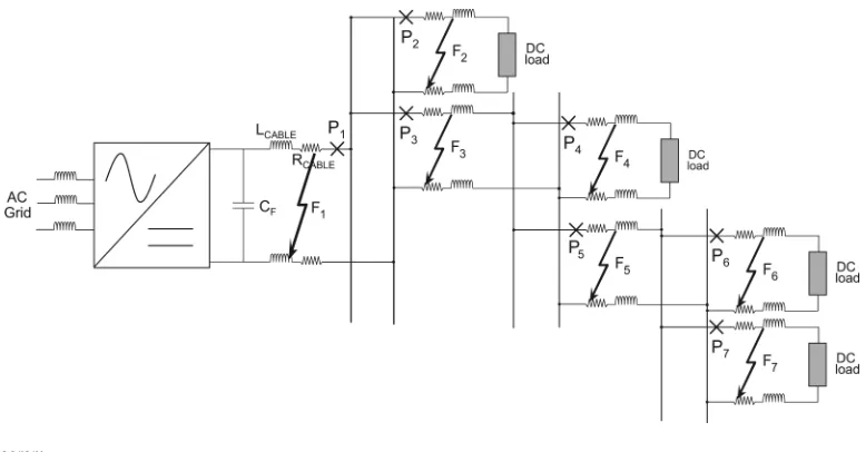
Fig. 1. Network diagram.
This paper first investigates the capability of non-unit pro-tection methods to achieve effective propro-tection discrimination within dc microgrid systems by analytically describing the
cur-rent, voltage, , and impedance response for a range
of fault locations and impedances. The particular difficulties of achieving fast acting and discriminative protection using non-unit methods are subsequently demonstrated using an analytical case study. Differential current behavior within dc microgrids is then analyzed, facilitating the identification of, and the proposal of solutions for, the challenging measurement and signal syn-chronization requirements for unit schemes. Finally, a protec-tion system design framework for dc microgrid applicaprotec-tions is proposed which provides optimal protection discrimination and operating speed whilst minimizing system installation costs.
II. QUANTIFICATION OF DCPROTECTIONSYSTEM
OPERATINGREQUIREMENTS
Cuzner [1] outline the key design criteria for any protection system and these relate to the operability and cost of a protec-tion system. From the criteria presented, the performance of the protection system is assessed on its ability to provide continuity of supply to loads where other parts of the network are experi-encing faults.
The dc microgrid network used as the basis for comparison within this paper is presented within Fig. 1, with Table I pre-senting relevant network parameters. This network has been de-rived from example architectures within literature [4], [7] and is supplied by a voltage source converter (VSC). Only a single source has been considered within Fig. 1 to simplify analysis and illustration however it is anticipated that findings will be applicable to networks with multiple sources. To ensure min-imum disruption to the network presented within Fig. 1 in the
event of a fault, protection devices to must operate in
a coordinated way, such that only the device immediately up-stream from the fault operates.
However there are a number of factors which influence the time-frame within which the network protection has to coordi-nate its devices operation. Many of these factors center around the use of use of a VSC as the main network supply.
TABLE I
NETWORKPARAMETERS
Previous work has highlighted that the fast discharge of capacitors used asfilters on the dc terminals of the VSC can damage both the capacitors themselves and any other sensitive components in the fault path [7]. Considerable short term electromagnetic forces on conductors can also be induced, cre-ating risks of physical damage to mountings or insulation [10]. Furthermore, [6] and [11] illustrate the potential for voltage reversal if dc side faults are not cleared within an adequate time frame. The voltage reversal can cause significant currents to
flow through converter freewheeling diodes, causing damage
to these devices.
The fault current withstand of VSCs is low compared to more robust thyristor based converter topologies [4], [7], therefore current must be limited or interrupted much more quickly to prevent damage to internal components when supplying fault current.
The typical topology of VSC devices is such if the back-bi-asing dc voltage is lost after the occurrence of a fault, the an-tiparallel diodes across the switching devices will begin to con-duct, meaning the converter is unable to block theflow of cur-rent to the fault [6], [12]. For these converter types, it neces-sary for network protection to act quickly to prevent damaging currents fromflowing through the diodes, within 2 ms in some cases [4].
Alternative VSC topologies contain their own internal pro-tection functionality, which enables the interruption of current
TABLE II
REQUIREDTRIPPINGTIMES FORUNDERVOLTAGETHRESHOLD OF200 VFOR A
1-m FAULT ATVARIOUSFAULTLOCATIONS
it is essential that the converter protection coordinates with
pro-tection devices to to ensure that only the appropriate
pro-tection device operates prior to converter propro-tection operation. Operational standards do exist for ac and HVDC systems which describe the requirements for converter connection in the event of network fault conditions. For example, [14] stipulates that in the event of a network undervoltage, converters are re-quired to remain connected for a minimum of 140 ms to avoid sympathetic tripping for faults elsewhere in the network [15]. However it is difficult to see how these requirements apply to less robust converter types, where connection for this period of time may result in theflow of damaging current magnitudes
flowing through the converter.
Whilst converter undervoltage protection is typically not as important as overcurrent for preventing device damage, for a dc system the undervoltage is a consequence offilter capacitor discharge, which in itself may cause problems. An undervoltage will be followed by an overcurrent condition on the ac side of the converter, as more current is drawn to attempt to recover the dc voltage. The dc side undervoltage can also be linked to the operation of ac side protection, which may monitor both dc voltage and current to determine its operation [13].
Given that the dc voltage is linked to a number of aspects of the network and converter protection, it is useful to consider the voltage response when deriving protection system operating criteria. The dc voltage response has the added advantage of
being least dependent on ac network conditions and confi
gu-ration, and hence provides a dc side solution which could be deployed within multiple applications. For these reasons, this paper assesses the potential for current fault detection methods to coordinate with a converter undervoltage threshold for the network described within Fig. 1.
To derive afixed operating point, an undervoltage threshold of 200 V (half the nominal system voltage) has been selected. It should however be noted that the observations in the following sections are relevant for various voltage thresholds. Table II highlights the time at which this voltage threshold is reached following the occurrence of a 1-m fault at the six fault loca-tions indicated in Fig. 1.
From Table II it is clear that, for the range of low impedance faults considered, the rapid loss of voltage at the converter ter-minals creates particularly challenging times for the operation of protection if it is to act to prevent the undervoltage occur-ring. The times identified are much shorter than required for ac converter connection [14], although they are in fact similar in magnitude to the requirements derived in [4] for prevention of
overcurrent, highlighting the unique challenges for the type of network considered.
The following sections will demonstrate the challenges in achieving discriminatory protection system operation within the time frames outlined using of non-unit methods.
III. ANALYSIS OFNON-UNITPROTECTIONMETHOD
EFFECTIVENESS
Non-unit protection does not protect a clearly bounded zone of the power system and will operate whenever its threshold is violated; non-unit schemes have inherent backup capabili-ties and will act to protect the system if a neighboring protec-tion system fails to operate [16]. Recent research [4], [7] out-lines approaches for the use of non-unit based protection scheme methods on microgrid and other multiterminal dc applications. Whilst non-unit approaches proved effective for the applica-tion considered, the architecture of these networks was such that there was not the requirement to coordinate upstream and down-stream devices in any significant way.
This section investigates the capability of non-unit protection methods to achieve effective protection selectivity, within the times derived within the previous section, for the more complex dc system illustrated within Fig. 1. The sectionfirst describes
the current, voltage, , , and impedance profiles as
measured at the generator converter terminals to enable a better understanding of the network fault response. To enable this anal-ysis to be more easily understood and usefully employed, sim-plifying assumptions have been made, which are based on pre-vious work by the authors and presented in [6]. The keyfindings from this analysis can then be considered for specific protection schemes and an example case study, based on an overcurrent scheme, is presented to illustrate the challenges faced.
A. Analysis of Dc Microgrid Fault Response
Under fault conditions, the initial current response of the net-work generally takes one of two forms depending on circuit
damping conditions [6]. For an underdamped circuit (defined
below), current can be defined as
(1)
where is the initial voltage onfilter capacitance . In
(1), the term represents the damped resonant frequency and
is defined as
(2)
is the damping factor (or Neper frequency) and is defined as (3)
the term is the resonant radian frequency and is defined as (4)
and and are the total resistance and inductance between the
discharging capacitor and the fault. Note that (1) assumes that
part the fault current characteristic is usually due to the initial voltage across the converterfilter capacitance [6].
The damping conditions in the network depend on the terms
and . The circuit is considered underdamped if ,
and overdamped if . For the overdamped case, current
is defined as
(5)
again neglecting initial current, and where
(6)
Current magnitude is often not used in itself to discriminate fault location but is also coupled with time, with a common
form being based on the response of the network. The
expressions for the two damping conditions, neglecting initial current, can be derived by squaring and integrating (1) and (5), respectively. These are
(7)
for underdamped conditions and
(8)
for overdamped network conditions.
Whilst it is more common to use current to detect faults,
al-ternative measures such as voltage [17], [18], [19],
and impedance [20] can be used for fault detection and are there-fore worthy of consideration. Conveniently, these can be de-rived from the current response, as described below.
The voltage response is proportional to the integral of current and, over the faulted period, can be represented by
(9)
for underdamped conditions and
(10)
for overdamped conditions.
To develop expressions for rate of current change, the deriva-tives of (1) and (5) are taken which gives
(11) and
(12)
respectively.
Expressions for the rate of change of voltage are found from the derivatives of (9) and (10), which are
(13)
and
(14)
respectively.
Finally the network impedance under fault conditions can be found from the division of the voltage expressions given in (9) and (10) by the equivalent current expressions presented in (1) and (5). In this manner, the underdamped response impedance can be expressed as
(15)
and the overdamped impedance is equal to
(16)
Having derived these expressions it can be seen how the var-ious circuit parameters shape the transient response. For
ex-ample, shows how the resistance and inductance parameters
affect the exponential decay. illustrates how the
combina-tion of all circuit parameters can affect oscillatory frequency and hence the peak current time. Finally (6) shows how the damping and frequency terms equate to give the roots of the characteristic equation and hence establish the appropriate equations to use in the analysis.
The equations can be analyzed in detail to describe a number of aspects of the different fault responses. However, for the pur-poses of this paper, there are two key characteristics which the analysis reveals.
First, the equations illustrate the impact of damping on the network response, emphasizing the high sensitivity of the different responses to fault impedance. This is a result of the relatively short interconnecting cables (and hence small cable impedance) within microgrids. The effect of this is that the response is less dependent on location for impedance faults, making discrimination more difficult. This leads to the design of protection schemes based more on time based grading and less on magnitude based grading, which is undesirable for the intended application given the tight requirements on protection system operating time. Both of these characteristics are exam-ined in further detail within [21].
One exception to this is the response under initial
This approach would however be limited to the protection of a single line, and so could not replace network wide protection.
Second, a comparison of all of equations, with respect to damping, highlights that they display similar behavioral char-acteristics. This is an unsurprisingfinding given that they are all derived from the capacitive response. As such, any conclu-sions regarding the effectiveness of non-unit protection methods drawn on the basis of current based methods will be relevant for all potential non-unit measurands.
The following section will demonstrate the challenges in im-plementing overcurrent techniques to provide effective protec-tion to the network illustrated in Fig. 1, looking specifically at
the network’s current and responses to a range of fault
con-ditions.
B. Illustration of Detection Challenges Based on an All Overcurrent Protection Scheme
To assess the capabilities of an overcurrent protection scheme to deliver the required levels of performance, this section looks at the coordination of pairs of upstream and parallel downstream devices, relating them to the previously derived operating re-quirements, and highlighting how these operating requirements differ depending on the connection of downstream devices. The merits of specific current-time graded protection schemes are not analyzed, as is perhaps more standard, as the authors be-lieve the issues are more clearly demonstrated with a study of network response rather than detailed device characteristics. It is worth noting however that a relay operated on the extremely inverse current-time characteristic (designed for fast operating conditions) would behave in a similar manner to that a device
operated on [16]. Furthermore, [23] does discuss the
poten-tial issues in coordinating current-time characteristics for net-works with large capacitive sources.
Whilst it is standard practice to coordinate protection device operation beginning with the furthest downstream device, the section insteadfirst assesses the coordination of upstream de-vices because of the challenges associated with operating close to the capacitive source and the impact this has on downstream protection operation. These challenges are illustrated in the fol-lowing sections.
1) Coordination of With and : To achieve good
performance when coordinating with and , the
protec-tion system must ensure that: any faults on line are quickly
discriminated and cleared and remains stable for faults on
downstream lines but provides backup in the event that or
fail to operate.
As will be shown in laterfigures, the detection and
discrim-ination of a low impedance fault at is reasonably straight
forward given the excessive overcurrent produced compared to more distant faults. Therefore the objective for the protection system for close up faults is to operate sufficiently quickly to prevent damage at the point of fault and to components sup-plying fault current. Instead, the key coordination challenge in
setting the overcurrent threshold at relates to the network
fault response for higher impedance faults. To illustrate why this is the case, consider the plot shown in Fig. 2.
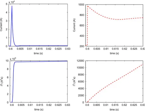
Fig. 2 illustrates the response of the network to 1- and
[image:5.592.302.553.63.255.2]500-m faults at , values which have been chosen to be
Fig. 2. Current (top) and (bottom) response for 1-m (left) and 500-m (right) faults at .
representative of low and high impedance fault conditions. It can be seen from Fig. 2 that for the two fault types, the peak fault current is vastly different, emphasizing the dominance of the fault impedance relative to the total fault path impedance. However in both cases the steady state output of the converter tends to the same level as the converter attempts to maintain output voltage to nominal levels. The magnitude of this steady state current will depend on either ac side fault level or con-verter rating (if the concon-verter is capable of limiting current for dc faults). Whilst the network voltage will not decay to the same extent for impedance fault conditions (and potentially not reducing below the defined voltage threshold), the operating requirement relates to the converter’s ability to supply this fault current.
This causes a problem in setting the overcurrent threshold for . For example, if an initial threshold is set for as the at the undervoltage threshold (set in the previous section as 0.9 ms,
at which point equals ), expanding the plot
for the 500-m fault within Fig. 2 will show that it takes 1.18 s
after fault inception to reach the same value. This would
lead to the converter supplying fault current for longer than de-sired, and hence there is a requirement to lower this operating threshold from this initial level. However to maintain coordina-tion with downstream devices, there is a limited degree to which this can be achieved. To assess the scope for the reduction,
con-sider the current and for 1 m fault at and shown in
Fig. 3. Note that due to faults and being the same distance
from the converter, and suitably low impedance, the responses to either fault is equivalent.
From a comparison of Fig. 3 and Table II it can be determined that the undervoltage threshold crossing at 2.2 ms corresponds
to an value of . Relating this value to the previous
fault case, is reached 0.16 s following the inception
of fault . Whilst this is perhaps longer than is
desir-able, it is reasonable to assume that the converter could supply current for this shorter time given the slower decay of dc side voltage. Therefore one protection setting option would be to
Fig. 3. Current (left) and (right) response for 1-m fault at and .
TABLE III
SUMMARY OFOPERATINGTHRESHOLDTIMES OF , ,
AND FOR AFAULT AT OR
suitable time margin between the operating points of upstream and downstream protection (to enable device coordination), it is
also necessary to reduce the thresholds of and . This
how-ever brings its own problems given the need for to coordinate
with further downstream devices and hence reducing the scope for threshold reduction. The necessity to reduce thresholds to achieve acceptable operating times does indicate that options to ride through the initial capacitive discharge, as suggested in [1] and [23], are limited.
To continue this example, consider the potential for circuit breaker coordination when reducing the threshold setting of
and to (half the original setting). Table III
sum-marizes the times at which the thresholds will be reached for the initial and revised protection settings.
Table III highlights that whilst the initial protection settings were challenging to meet because of the short time frame, a
sufficient time margin existed between upstream and
down-stream protection to ensure coordinated protection operation. However given the requirement to reduce the upstream threshold to achieve reasonable operating times, the subsequent impact means that the time margin between device operations has reduced to a level such that on protection coordination is extremely difficult to achieve. This is in part due to the typical delay time between detection and circuit breaker operation, and this is discussed in more depth in later a section.
In order to increase the time margin between different de-vice operations, there may be some scope for reduction in the threshold of , albeit limited, given that it does not need to co-ordinate with further downstream devices. This is not the case for , so further reduction in its threshold is not necessarily an option. To quantify this, the following sections investigate the impact of upstream device coordination on the response of downstream protection.
2) Coordination of With and : The potential for
threshold reduction can be examined from analysis of
down-stream faults . The initial threshold for , derived from
TABLE IV
SUMMARY OFOPERATINGTHRESHOLDTIMES OF , ,
AND FOR AFAULT AT OR
TABLE V
SUMMARY OFOPERATINGTHRESHOLDTIMES OF
AND FOR AFAULT AT
the undervoltage cut off, is . As this is greater than
the revised threshold for in the previous section, there is
a need to reduce this level. To maintain consistency with the
previous section, the threshold for has been reduced to
(half that of ). A summary of the impact of
this on required operating time and time margins is shown in Table IV.
Table IV highlights that the difference in required operating time for the initial undervoltage thresholds is already very tight and the impact of the reduced operating threshold compounds this problem, making the setting of devices extremely difficult. As with the previous case, given that the required operating time is already small, there is little scope for accelerating protection operation through threshold reduction. However for complete-ness, and to quantify challenges further downstream protection, the following section assesses the options for coordination of
with and .
3) Coordination of With and : In a similar manner
to the previous section, the potential for device coordination is assessed through comparison of the initial and revised
over-current thresholds. The initial threshold for or was
, which is again greater than revised upstream
levels, and so in line with previous sections the it has been
reduced to (half of ). A summary of initial and
revised operating times for a fault at is presented in Table V. Table V shows a similar trend to the previous section in terms of both required operating time and time difference between up-stream and downup-stream devices. Therefore the device coordina-tion challenges are similar to those reported previously.
C. Discussion of Results
The results presented in the previous sections have demon-strated the significant challenges which exist in the coordina-tion of proteccoordina-tion in compact dc power systems, within the time constraints imposed by converter interfaces, using overcurrent based protection schemes.
In each scenario it was illustrated that the time margin be-tween upstream and downstream protection operation was pro-hibitively small, creating a risk of upstream protection opera-tion for downstream faults. This was in part due to the tight op-erating requirements from the network voltage response.
How-ever the need for reduction in the threshold of (to achieve
has a cascading effect on the downstream device settings and hence reduces operating margins. From this, it is worth noting in Table IV and V the time difference between the initial up-stream and the revised downup-stream threshold is twice that of the difference between the two initial settings. This suggests that if the constraint of lowering the upstream threshold is removed, a greater opportunity for device coordination exists, provided op-erating requirements are met.
It is also worth considering how the difference in required op-erating time compares to that of the physical opop-erating speeds of circuit breakers. Previous work by the authors [6] highlights that the requirement for fast acting protection can limit the range of protection devices which can be employed in dc microgrid networks. For example, the operating time of dc electro-me-chanical circuit breakers (EMCBs) can be from around 3 ms [24], which exceeds the time difference in the scenarios de-scribed in the previous section, meaning coordination is not nec-essarily possible using the methods presented. Solid state and hybrid circuit breaker technologies offer a potential alternative to EMCBs, as these breakers can operate extremely quickly after the detection of a fault, however there are greater limitations on the operating voltage and current levels of these devices than for EMCBs.
It must also be appreciated that dc current breaking cannot be achieved instantaneously and there is afinite time when cur-rent is driven to zero. During this period curcur-rent will continue to
flow through upstream devices [25] and this could, depending
on network conditions, cause an upstream device to operate be-fore the fault is fully cleared.
Acknowledging these shortfalls, it can be concluded that the non-unit methods analyzed are unlikely to be able to achieve the required levels of protection discrimination for the derived op-erating requirements. Within future dc networks it is likely that a higher level of fault discrimination will be desirable, particu-larly if dc is to be proven a viable alternative to ac distribution. For these future networks, it has been demonstrated that for this to be achieved, more robust protection approaches are required. The following section investigates the potential for unit protec-tion schemes to provide this required protecprotec-tion performance and proposes commercial off the shelf (COTS) based solutions for the key challenges identified. This analysis subsequently en-ables the development of a protection framework for dc micro-grid applications.
IV. APPLICATION OFUNITPROTECTION
Unit protection protects a clearly bounded zone of the power system and will not operate for faults external to this zone. In contrast to non-unit schemes, it does not provide backup to ad-jacent elements of the system [26] hence non-unit protection is often deployed alongside unit protection to provide the neces-sary backup functionality. A common form of unit protection is current differential protection, which operates by comparing all currents’ magnitudes and/or relative directions at the bound-aries of a specified element within a network [26].
The nature of the current differential protection method is such that it is far less susceptible to the effects of variable fault levels and impedances than non-unit methods [27], facilitating effective protection coordination in the network. However, the
major challenge which remains for the implementation of a dif-ferential protection scheme within dc microgrids is the capa-bility to achieve fault detection within the time frame described in previous sections.
In addition to the technical constraints, the economics of the protection system implementation must also be considered [1]. The requirements for device communication means the instal-lation costs of a current differential scheme can be substantial compared to an overcurrent scheme, particularly at the distri-bution level, although this might be somewhat reduced for mi-crogrid systems due to their relatively small geographical area. However, given the likely increase in the amount of sensor and communication infrastructure within distribution networks [9] as smart grid and microgrid [8] concepts develop, much of the required infrastructure may already be in place. The deployment of this advanced infrastructure therefore provides an opportu-nity to expand the use of unit (communication-based) protection schemes within microgrids.
To explore this opportunity, this section considers two as-pects to the implementation of current differential protection. Thefirst aims to quantify these implementation challenges and the second considers the impact of unit protection implemen-tation on overall protection. These aspects are described in the following subsections.
A. Challenges and Proposed Solutions for the Implementation of Fast Acting Unit Protection Schemes
There are two main challenges for the implementation of unit protection within the highly transient environment described in the previous sections. Thefirst is, can currents be compared and fault location determined within the required time frame? The second is, can the current measurements at different points in the network be accurately synchronized to ensure correct protection system operation? These issues are discussed in the following sections.
1) Challenges in Meeting the Operating Requirement:
Cur-rent diffeCur-rential protection applied in ac systems typically has a target operation time of 1–2 cycles, which often represents an operation time of 20 ms [28], [29]. In comparison, the oper-ating times derived in Section II are much shorter and hence alternative implementation methods must be deployed in order to meet these operating times.
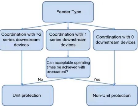
Fig. 4. Protection scheme approach decision tree.
communications system in order to operate effectively within the derived operating times. Exact specification of these require-ments is an area of future work.
2) Challenges in the Implementation of Unit Systems When
Operating Under High Rate of Change Fault Conditions: To
avoid the occurrence of errors in the current differential sum, and hence ensure that the scheme performs correctly, current measurements must be synchronized in time [26]. There are a number of potential sources of poor time synchronization. These include timing errors between communicating devices and non-synchronous current sampling. Given the high rate of current change in the fault response considered within this paper
(ini-tially 17 A s for a fault at for example), accurate
de-vice synchronization becomes even more important to ensure the protection scheme does not mal-operate.
To minimize the impact of this on the protection system oper-ation in practice, protection relays often communicate both cur-rent and time information to ensure curcur-rent measurements are compared in the same point in time. Synchronization using this approach can be most effectively achieved where devices are synchronized through GPS time stamping [28], where devices
are synchronized with an accuracy of . It is anticipated
that this degree of accuracy would be sufficient however if the time difference was to increase then there is a possibility of large errors occurring within the differential sum.
B. Protection System Design Framework for DC Microgrid Applications
In this section, a protection system design framework is proposed which provides clear design guidance with which to achieve fast and effective protection system operation, whilst seeking to minimize installation costs, against a set of very strict operating requirements. It achieves this by proposing the use of unit protection upstream within a network in order to ease the constraints on downstream non-unit protection. Fig. 4 provides a pictorial overview of the design framework.
The proposed framework provides guidance on the required protection approach for a feeder based on its position within the network and the surrounding elements of this network. In this manner, unit protection methods (with non-unit backup) are
recommended for feeders where coordination with downstream devices is likely to be difficult within an acceptable time frame, but non-unit protection is recommended for all other cases in order to balance required system performance against installa-tion cost. This framework is applicable to dc microgrids of var-ious configurations.
To illustrate the underlying philosophy of this scheme, con-sider the example microgrid network illustrated in Fig. 1. If a current differential scheme were to be applied between the supply converter output and thefirst parallel connection point
(prior to and ) in place of an overcurrent scheme, it would
serve to remove the constraint of reducing the threshold to
achieve acceptable operating times under impedance fault con-ditions. This could be achieved as the unit protection zone would be insensitive to external faults and hence not operate even with high current throughput. The subsequent effect of this would be to enable the remainder of the protection settings within the net-work to return to the initial values derived from the time of un-dervoltage, increasing the time margin between the operation of different devices. However this still leaves very tight operating time requirements, particularly where devices have to coordi-nate with other downstream protection devices.
Additionally, Section III-B shows that the time margin
be-tween adjacent devices from onwards is similar, and this is
due to the uniform fault separation and cable parameters within the network. To adhere to requirement of operating protection prior to a network undervoltage, it has been shown that the only means of increasing this time margin is to decrease the
down-stream threshold. This is possible between and , however
due to the connection of additional parallel loads downstream
for , potential reduction in the overcurrent threshold at
is limited. The application of unit protection at each of these parallel connection points would not only ensure accurate fault detection for internal zone faults but also that there is sufficient time available for the operation of protection devices for load connection points. Protection of these parts of the network could be achieved through the use of simpler non-unit techniques.
V. CONCLUSION
ACKNOWLEDGMENT
This work has been carried out as part of the Rolls-Royce UTC program.
REFERENCES
[1] R. Cuzner and G. Venkataramanan, “The status of DC micro-grid pro-tection,” inProc. IEEE Ind. Appl. Soc. Annu. Meeting (IAS), Oct. 2008, pp. 1–8.
[2] K. George, EPRI Solutions, Inc., “DC power production, delivery and utilization: An EPRI white paper,” 2006.
[3] K. Shenai and K. Shah, “Smart DC micro-grid for efficient utilization of distributed renewable energy,” presented at the IEEE Energytech, Cleveland, OH, May 2011.
[4] D. Salomonsson, L. Soder, and A. Sannino, “Protection of low-voltage DC microgrids,” IEEE Trans. Power Del., vol. 24, no. 3, pp. 1045–1053, Jul. 2009.
[5] T. Kaipia, P. Salonen, J. Lassila, and J. Partanen, “Application of low voltage DC-distribution system—A techno-economical study,” presented at the 19th Int. Conf. Elect. Distrib., Vienna, Austria, May 2007.
[6] S. Fletcher, P. Norman, S. Galloway, and G. Burt, “Determination of protection system requirements for DC unmanned aerial vehicle elec-trical power networks for enhanced capability and survivability,”IET Elect. Syst. Transp., vol. 1, no. 4, pp. 137–147, 2011.
[7] M. E. Baran and N. R. Mahajan, “Overcurrent protection on voltage-source-converter-based multiterminal dc distribution systems,”IEEE Trans. Power Del., vol. 22, no. 1, pp. 406–412, Jan. 2007.
[8] G. Venkataramanan and C. Marnay, “A larger role for microgrids,”
IEEE Power Energy Mag., vol. 6, no. 3, pp. 78–82, May-Jun. 2008. [9] V. Sood, D. Fischer, J. Eklund, and T. Brown, “Developing a
commu-nication infrastructure for the smart grid,” inProc. IEEE Elect. Power Energy Conf. (EPEC), Oct. 2009, pp. 1–7.
[10] Short-Circuit Currents in DC Auxiliary Installations in Power Plants and sSubstations—Part 2: Calculation of eEffects, IEC 61660-2:1997, International Electrotechnical Commission, 1997.
[11] J. Yang, J. Fletcher, and J. O’Reilly, “Multiterminal dc wind farm col-lection grid internal fault analysis and protection design,”IEEE Trans. Power Del., vol. 25, no. 4, pp. 2308–2318, Oct. 2010.
[12] L. Tang and B.-T. Ooi, “Locating and isolating DC faults in multi-terminal DC systems,”IEEE Trans. Power Del., vol. 22, no. 3, pp. 1877–1884, Jul. 2007.
[13] J. Candelaria and J.-D. Park, “Vsc-hvdc system protection: A review of current methods,” inProc. IEEE/PES Power Syst. Conf. Expo. (PSCE), Mar. 2011, pp. 1–7.
[14] National Grid Electricity Transmission plc, “The grid code,” no. 4, revision 1, May 16, 2010 [Online]. Available: http://www.national-grid.com/uk/Electricity/Codes/gridcode/
[15] K. I. Jennett, C. D. Booth, and L. Martin, “Analysis of the sympathetic tripping problem for networks with high penetrations of distributed generation,” presented at the Int. Conf. Adv. Power Syst. Autom. Prot., Beijing, China, Oct. 2011.
[16] “Overcurrent protection for phase and earth faults,” inNetwork Protec-tion and AutomaProtec-tion GuideALSTOM, 2011, ch. 9 [Online]. Available: www.alstom.com/grid
[17] R. M. Tumilty, M. Brucoli, G. M. Burt, and T. C. Green, “Approaches to network protection for inverter dominated electrical distribution sys-tems,” inProc. IET 3rd Int. Conf. Power Electron., Mach. Drives, Mar. 2006, pp. 622–626.
[18] E. Cinieri, A. Fumi, V. Salvatori, and C. Spalvieri, “A new high-speed digital relay protection of the 3-kvdc electric railway lines,”IEEE Trans. Power Del., vol. 22, no. 4, pp. 2262–2270, Oct. 2007. [19] S. Foster, L. Xu, and B. Fox, “Control of an LCC HVDC system for
connecting large offshore wind farms with special consideration of grid fault,” inIEEE Power Energy Soc. Gen. Meeting, Jul. 2008, pp. 1–8. [20] “Distance protection,” inNetwork Protection and Automation Guide
ALSTOM, 11 [Online]. Available: www.alstom.com/grid
[21] S. Fletcher, P. Norman, S. Galloway, and G. Burt, “Analysis of the effectiveness of non-unit protection methods within dc microgrids,” presented at the IET Conf. Renew. Power Gen., Edinburgh, U.K., Sep. 2011.
[22] S. D. A. Fletcher, P. J. Norman, S. J. Galloway, and J. E. Hill, “Protec-tion system for an electrical power network,” U.K. Patent applica“Protec-tion GB1102031.0, Feb. 2011.
[23] R. Cuzner, D. MacFarlin, D. Clinger, M. Rumney, and G. Castles, “Cir-cuit breaker protection considerations in power converter-fed DC sys-tems,” inIEEE Elect. Ship Tech. Symp., Apr. 2009, pp. 360–367. [24] “Secheron high-speed dc circuit-breaker for rolling stock type UR26,”
2011. [Online]. Available: http://www.secheron.com
[25] S. D. A. Fletcher, P. Norman, S. Galloway, and G. Burt, “Solid state circuit breakers enabling optimised protection of dc aircraft power sys-tems,” presented at the 14th Eur. Conf. Power Electron. Appl. (EPE), Birmingham, U.K., Sep. 2011.
[26] “Unit protection of feeders,” inNetwork Protection and Automation
GuideALSTOM, 10 [Online]. Available: www.alstom.com/grid
[27] P. Karlsson and J. Svensson, “Fault detection and clearance in DC dis-tributed systems,” presented at the Nordic Worskshop Power Ind. Elec-tron., Stockholm, Sweden, Aug. 2002.
[28] N. Villamagna and P. Crossley, “A symmetrical component-based GPS signal failure-detection algorithm for use in feeder current differential protection,”IEEE Trans. Power Del., vol. 23, no. 4, pp. 1821–1828, Oct. 2008.
[29] SEL-inc, “SEL-311L line current differential protection and automa-tion system,” 2011. [Online]. Available: http://www.selinc.com
Steven D. A. Fletcherreceived the B.Eng. (Hons) degree in electrical and elec-tronic engineering from the University of Strathclyde, Glasgow, U.K., in 2007, where he is currently working toward the Ph.D. degree.
He is currently a Research Assistant with the Institute for Energy and En-vironment, University of Strathclyde. His research interests include the tran-sient analysis and protection of dc systems for microgrid, marine, and aerospace applications.
Patrick J. Normanreceived the B.Eng. (Hons) degree in electrical and mechan-ical engineering and Ph.D. degree in electrmechan-ical engineering from the University of Strathclyde, Glasgow, U.K.
He is a Full-Time Research Staff Member with the Institute for Energy and Environment, University of Strathclyde. He has published over 35 peer reviewed journal and conference publications. His current research interests lie in the modeling and simulation, design, control, protection of aircraft secondary power offtake and distribution systems, and microgrid and shipboard power systems.
Stuart J. Gallowayreceived the Bachelors degree in mathematical sciences from the University of Paisley, Paisley, U.K., in 1992, and the M.Sc. degree in nonlinear modeling and Ph.D. degree in numerical analysis from the University of Edinburgh, Edinburgh, U.K., in 1993 and 1998, respectively.
He is currently a Senior Lecturer with the Institute for Energy and Environ-ment, University of Strathclyde. Since 1998, he has been researching optimiza-tion problems in power systems, electricity markets, and novel electrical archi-tectures relating to aero and marine electrical systems.
Paul Crolla(M’06) received the M.Sc. degree in physics from the University of Strathclyde, Glasgow, U.K., in 2005.
He is currently a Research Assistant with the Protection, Automation and Control Team, Institute for Energy and Environment, University of Strathclyde. His main research interests lie in the development of power hardware-in-the-loop applications and power systems laboratory demonstration.
Graeme M. Burt(M’95) received the B.Eng. degree in electrical and electronic engineering and the Ph.D. degree from the University of Strathclyde, Glasgow, U.K., in 1988 and 1992, respectively, following research into fault diagnostic techniques for power networks.