ANALYSIS AND CALCULATION'OF FIBER TO FIBER CONNECTION LOSS
SIT1 NURI-IAZA BINTI MOHD RAMLI
This report is submitted in partial fulfillment of the requirements for the award of Bachelor of Electronic Engineering (Computer Engineering) With Honours
Faculty of Electronic and Computer Engineering Universiti Teknikal ~ a l a ~ s i a ' ~ e 1 a k a
UNIVERSTI TEKNIKAL MALAYSIA MELAKA
FAKU1,TI KEJURUTERAAN ELEKTRONIK DAN KEJURUTERAAN KOMPUTER BORANG PENGESAllAN STATUS LAPORAN
PROJEK SARJANA MUDA 11
Tajuk Projek
.
ANALYSIS AND CALCULATION OF FIBER TOFIBER CONNECTION LOSS
Sesi
Pengajian : 2008/2009
Saya ... SIT1 NURHAZA BINTI MOlID RAMLI ... (IIURUF BESAR)
mengaku membenarkan Laporan Projek Sarjana Muda ini disimpan di Perpustakaan dengan syarat-syarat kegunaan seperti berikut:
1. Laporan adalah hakmilik Universiti Teknikal Malaysia Melaka.
2. Perpustakaan dibcnarkan membuat salinan untuk tujuan pengajian sahaja.
3. Perpustakaan dibenarkan membuat salinan laporan ini sebagai bahan pertukaran antara institusi pengajian
tinggi.
4. Sila tandakan (
4
) :1
1
SIJLIT*(Mengandungi maklumat yang berdarjah keselamatan atau kepentingan Malaysia seperti yang termaktub di dalam AKTA
RAHSlA RASMl 1972)
TERHAD* (Mengandungi maklumat terhad yang telah ditentukan ole11 organisadbadan di mana penyelidikan dijalankan)
]
TIDAK TERHADDisahkan oleh:
AN PENULIS) (COP DAN TANDATANGAN PEJ4lELIA) YOSZA Ub.S.2: Alamat Tetap:
. ~ . ~ P . u I \ ~ ~ . . ~ ~ . w . . K ~ P u H
&?@') Pet,sy arahlelYMe,aan Ei,saror;k DSn
* e p : u ' ~ ~ " ' '" ' I ' , K,. . , : . L * . :
. a , v , ,
, ieknira\ Malaysba
' I"
xiTB
PkMbW, ~ - S \ ~ M B I L ~ ~ e r k u n c i No'
' ."' ...pejabat pas Durian TunWd'
76,0g ,-,,,ian ~,.inggal. h4eiaha
1q-41
Wo
9
iii
DECLARATION
"1 hereby declare that this report is the result of my own work except for quotes as cited the reference"
Signature Author
"I hereby declare that I have read this report and in my opinion this report is sufficient in terms of the scope and quality for the award of Bachelor of Electronic
Enigineering(C0mputer Engineering) With Honours"
DR. Y O S u b ~ % % : i -
pensyarah
~ n d t [ K-~~~ Elektrmik Dan Ke~*:~::--r.r:ii <.' Ci...3
Signature :
...
~ e r s j t j . ~ a k o j k i . M ? j ? ~ S i a Karung Berkund .N'd.lEr.. Me1w.a ~ ~ J T * M I...
Supervisor'sName :
...
9etabatPob~wjan.~rmggel...
To My parents
Mohd Ramli b. Ismail& Rahimah bt Md. Ramli
My siblings,
Mastura, Nurhafizah, Nur Aida Adila, Mohd Azrul Hisyam & Nur Azila Umairah
ACKNOWLEDGEMENT
A very thankful to GOD because of His blessing, i can finish final year project 1. I am very thankful for all assistance that has been offered in the process of completing the report.
Here, I would like to express my utmost gratitude to the academic advisor, Dr. Yosza Dasril and En. Chairulsyah for their patient, guidance and advice. I would also like to show my appreciation to my friends, especially Siti Noraishah and Nor Rifhan who give me a lot of help in guide and teach me of solving my problem.
ABSTRAK
Dalam kajian ini, saya telah membangunkan sebuah kalkulator menggunakan bahasa pengaturcaraan Visual Basic 6.0 yang dapat digunakan untuk mengira komunikasi putus pada sambungan fiber optik. Kalkulator ini digunakan untuk mengira komunikasi putus jenis sambungan fiber tunggal,' multimode Jiber step index' dan 'multimode fiber graded index'.
ABSTRACT
In this research, the software calculator has been build using Visual Basic .O. This software calculator can calculate connection loss of fiber optic. This calculator to calculate connection loss in single mode fiber, multimode fiber step index and multimode fiber graded index.
TABLE OF CONTENT
CHAPTER TITLE
TITLE APPROVAL FORM DECLARATION DEDICATION ACKNOWLEDGEMENT ABSTRAK ABSTRACT
TABLE OF CONTENT
LIST OF FIGURE
LIST OF APPENDIX
1 INTRODUCTION
1.1 INTRODUCTION
1.2 BACKGROUND OF STUDY 1.3 OBJECTIVE
1.4 SCOPE OF WORK 1.5 OUTLINE OF REPORT
2 LITERATURE REVIEW
2.1 BACKGROUND STUDY
2.2 LITERATURE REVIEW 2.2.1 OPTICAL FIBER
2.2. l .I Construction Optical Fiber
2.2.2 TYPES OF AN OPTICAL FIBER 2.3 SPLICING
2.3.1 TYPES OF SPLICING 2.3.1.1 Fusion Splicing Method 2.3.1.2 Mechanical Splicing Method 2.4 CONNECTOR LOSSES 2.4.1 Intrinsic Losses
2.4.2 Extrinsic Losses
3 RESEARCH MTHODOLOGY
3.1 PROJECT METHODOLOGY 3.2 PROCESS OF FLOW CHART 3.2.1 Explanation of Flow Chart 3.2.2 Software Development
3.4 CALCULATOR DISPLAY DESIGN
4 RESULT 31
4.1 ANALYZE FIBER OPTIC CONNECTION 3 1
4.1.1 Single Mode Fiber 3 2
4.1.2 Multimode Fiber 33-34
4.2 SOFTWARE CALCULATOR CALCULATION 34-35
5 CONCLUSION 44
5.1 MOTIVATION AND DEVELOPMENTMETHOD . 44
5.2 DISCUSSION 44-45
5.3 CONCLUSION 46-47
REFERENCE
LIST OF FIGURE
TITLE PAGE
Optical fiber Optical fiber cable
Construction of optical fiber Multimode optical fiber Multi-mode graded index Multimode step index
Single mode optical fiber
Single mode fiber's light propagate Fusion splicing with apparatus
Mechanical splicing with ceramic alignment NA mismatch
Core diameter mismatch
Show the connection of lateral misalignment; (a) Side view (b)Top view (c) Horizontal view
Basic construction angular misalignment; (a) Side view (b) Top view (c) Horizontal view
Basic construction of end separation; (a) Side view (b) Top view (c) Horizontal view
Lateral misalignments due to overlap
Graph for loss connection in multimode step index fiber The angular misalignment position
Graph for angular misalignment losses in different numerical aperture
End separations with refractive index of matching fluid Graph loss end separation for different numerical aperture Process of flow chart to design the software calculator
Front page of calculator display chosen types of fibers, example selected cases and exit button
Example page end separation case display all the parameter including in formula, result, picture and formula selected case, calculator button, back to case button and exit button.
Light propagate in single mode fiber and shape of graph Light propagate in single mode fiber and shape of graph First page of software calculator
Result calculation after insert value of parameter angular misalignment of single mode fiber. The answer below OdB and message box appear
GUI for core diameter calculator
After insert the value of diameter and the answer Single mode fiber with the types of cases
Angular misalignment GUI calculator End separation GUI single mode fiber Angular misalignment GUI
GUI for lateral misalignment in multimode step index fiber GUI for core diameter for multimode step index and multimode graded index fiber
GUI for numerical aperture for multimode step index and
multimode graded index fiber
xiv
LIST OF APPENDIX
NO TITLE PAGE
A TABLE FOR SOME COMMON FIBER TYPER AND
THEIR PROPERTIES 48
CHAPTER I
INTRODUCTION
1.1 INTRODUCTION
Misalignment and hetergonic of fiber optic cable in splicing process will effect to the attenuation loss in fiber optic link. This project will design software to calculate the effect of loss which is caused of position misalignment and hetergonic of fiber optic cables to connect. Types of losses connection fiber connection are distance between fiber cables, the way how fiber cable connected, angular between fibers connecter and other. It will be helpful software to support fiber optic learning process. The Visual Basic will be use for guide interface user (GUI), formula and calculating support. This calculator easier to use by inserting the value of parameter such as angle ( O ) , distance, offset value between joining cores of fiber optic and other
value. The result will display automatically. The task of this project is to study literature, software design and testing.
1.2 BACKGROUND OF STUDY
misalignment using Visual Basic 6.0. This software calculator will display the formula and picture how misalignment connections look alike.
1.3 OBJECTIVE
The objectives of this project are:
4 to study and analyze types of losses of fiber optic
4 to design friendly software calculator by using VB6.0
4 to test the reliability of software calculator.
1.4 SCOPES OF STUDY
1.5 OUTLINE OF REPORT
CHAPTER 1 will be describe the definition of the project. The explanation about this project also include in this chapter. It also introduces the project before do the literature review.
CHAPTER 2 will be discussing about the information and all the research that have the related with this project. Each fact and information that related with this project is get from the different references such as book title, journal and other.
CHAPTER 3 will be explaining about design of software. It was including the coding code to make the software calculator.
CHAPTER 4 is describing about the project result and outcome discovery. The project outcome discovery will be presented from data analysis result.
CHAPTER 2
LITERATURE REVIEW
2.1 BACKGROUND STUDY
This is background study on this topic related to the project that is about splicing in fiber optic. This is also about step to splice, characteristics and types of optical fiber.
2.2 LITERATURE REVIEW
2.2.1 Optical Fiber
An optical fiber is simply a very thin piece of glass which acts as a pipe, through which light can pass down. The light .can be turn on and off to represent digital information. Besides that, it can be gradually change in amplitude, frequency or phase to represent analog information. It's widely used in fiber optic communication which permits transmission over longer distance and at higher data rates than other forms of wired and wireless communication. [3]
Normally, it will be used with the design and the wavelength of light of the propagating in the fiber. From that, the type of fiber optic will determine either multi-mode optical fiber or single-mode optical fiber. Based on their uses, the fibers are built into different kind of cable.
2.2.1.1 Construction of an Optical Fiber
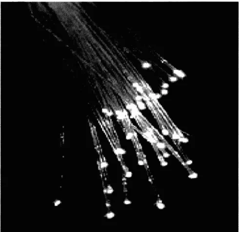
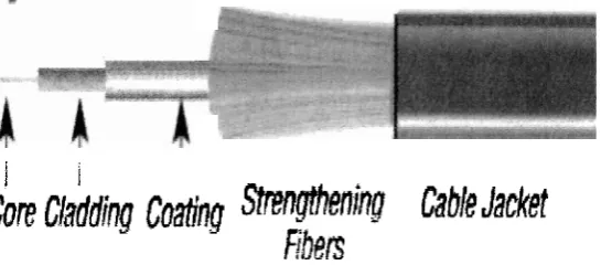
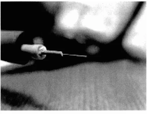
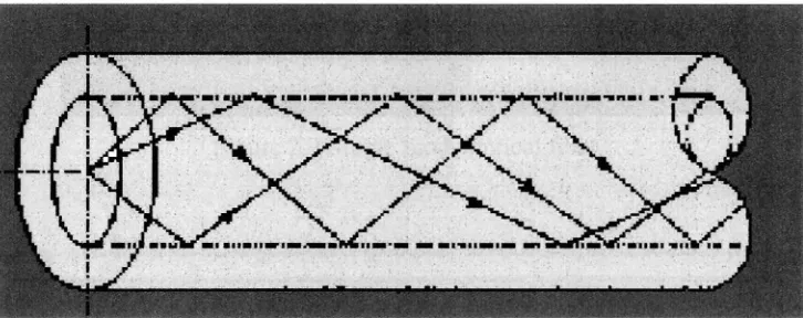
[image:19.540.152.398.466.705.2]An optical fiber consist a tube of glass constructed of a number of layers of glass. It will be appear to have a number of concentric rings when looked at profile. The illustrate layer of glass as shown in figure 2.2. Each layer or known as ring have a different refractive index. From the previous discussion, it can be seen that the requirement that total internal reflection occur needed to send light down the center of these concentric glass tubes. This will be duct the light through a fiber. The outer glass require a lower refractive index than the inner glass tube in which the light is traveling to achieve total internal reflection the outer glass ring [I]. Figure 2.1 until Figure 2.3 illustrates the construction of a typical optical fiber.
Figure 2.2 Optical fiber cables
I
ICore
Cladding
Coaling
mming
CableJadet
F i b t ~
Figure 2.3 Construction of optical fiber
2.2.2 Types of Optical Fiber
There are three variety types of optical fiber such as single-mode fiber, multi- mode step index and multi-mode step index fiber. Each of them has their specification. For example, multimode optical fiber mostly used for communication over shortest distance like within a building or on link lengths of up to 550meters, more the sufficient for the majority of premises application.
generally used for backbone application in building because of the high capacity and reliability.
Multi-mode optical fiber has a higher 'lighting gathering' capacity compare to single-mode optical fiber. However, the limit on speed x distance is low because multi-mode optical fiber has a larger numerical aperture (NA) that support more than propagation mode. Hence, it is limited by modal dispersion compare to single- mode that has a higher limit on speed x distance. So, single-mode optical fiber has smallest numerical aperture (NA). Consequently, multi-mode optical fiber has higher pulse spreading rates than single-mode optical fiber. Due of this reason, multi-mode has limiting information transmission capacity [ 7 ] .
[image:21.540.148.439.470.695.2]Multi-mode optical fibers are described by their core or cladding diameter. Thus, 62.51125pm has a core size 62.5pm and cladding diameter 125pm. Figure 2.4 show the multimode optical fiber while Figure 2.5 and figure 2.6 are illustrates the information transmission capacity of multi-mode step index and multi-mode graded index.
Figure 2.5 Multimode graded index fiber' light propagate
Figure 2.6 Multimode step index fiber's light propagate
Figure 2.7 Single mode optical fiber
Figure 2.8 Single mode fiber's light propagate
Unlike multi-mode optical fiber, single mode fibers do not exhibit dispersion resulting from multiple spatial modes. It's also better at retaining the fidelity of each light pulse over long distances than are multi-mode fibers. Due of this reason, single-mode fibers can have a higher bandwidth compare to multi-mode fibers. Besides that, equipment for single-mode fiber is more expensive than equipment for multi-mode fibers but single-mode fiber usually cheaper in bulk[5].
[image:23.541.74.483.388.478.2]special properties such as dispersion-shifted fiber. Data rates are limited by polarization mode dispersion and chromatic dispersion[5].
2.3 SPLICING
There are many source splice loss in the optical fiber. One of them is the different between two fibers. Although optical fiber is made to very precise specification, there are still very slight differences between fibers. It can know when the numerical aperture (NA) of the transmitting fiber is larger than the receiving fiber or when the core diameter of transmitting fiber is larger, it's may cause some losses. For example, loss can produce if the cores are not perfectly circular unless they are perfectly lined up. Even the cladding makes a difference in the cladding; its can caused the core to be misalignment. Fiber manufacturers have made much progress in reducing these problems. Fiber produce to a Smicron tolerance has a maximum loss of 0.6dB. It newer manufacturing techniques allow tolerance of 1 (0. ldB) to 2 (0.2dB) microns.
Connecting two fiber optic cables requires precise alignment of the mated fiber cores or spots in a single-mode optical fiber cable. So that, it's required all the light is coupled from one fiber-optic cable across a junction to the other fiber optic cable.
2.3.1 Types of Splicing