UNIVERSITI TEKNIKAL MALAYSIA MELAKA
DESIGN AND DEVELOPMENT ROBOT DRIVE SYSTEM USING
MECANUM WHEEL
This report submitted in accordance with requirement of the Universiti Teknikal Malaysia Melaka (UTeM) for the Bachelor Degree of Manufacturing Engineering
(Robotic and Automation) with Honours.
by
ZUL AZRI BIN ZAINAL B050810123
UNIVERSITI TEKNIKAL MALAYSIA MELAKA
BORANG PENGESAHAN STATUS LAPORAN PROJEK SARJANA MUDA
TAJUK: Design and development robot drive system using Mecanum Wheel
SESI PENGAJIAN: 2010/11 Semester 2
Saya ZUL AZRI BIN ZAINAL
mengaku membenarkan Laporan PSM ini disimpan di Perpustakaan Universiti Teknikal Malaysia Melaka (UTeM) dengan syarat-syarat kegunaan seperti berikut: 1. Laporan PSM adalah hak milik Universiti Teknikal Malaysia Melaka dan penulis. 2. Perpustakaan Universiti Teknikal Malaysia Melaka dibenarkan membuat salinan
untuk tujuan pengajian sahaja dengan izin penulis.
3. Perpustakaan dibenarkan membuat salinan laporan PSM ini sebagai bahan pertukaran antara institusi pengajian tinggi.
4. **Sila tandakan (√)
SULIT
TERHAD
TIDAK TERHAD
(Mengandungi maklumat yang berdarjah keselamatan atau kepentingan Malaysia yang termaktub di dalam AKTA RAHSIA RASMI 1972)
(Mengandungi maklumat TERHAD yang telah ditentukan oleh organisasi/badan di mana penyelidikan dijalankan)
Alamat Tetap:
AE 2-2, Jalan Pandan Indah 3/3, Pandan Indah,
55100 Kuala Lumpur, Pahang.
Tarikh: 18 May 2011
Disahkan oleh:
PENYELIA PSM
DECLARATION
I hereby, declared this report entitled “Design and development a robot drive system using mecanum wheel” is the results of my own research except as cited in references.
Signature : ………..
Author’s Name : ZUL AZRI BIN ZAINAL
APPROVAL
This report is submitted to the Faculty of Manufacturing Engineering of UTeM as a partial fulfillment of the requirements for the degree of Bachelor of Manufacturing Engineering (Robotic and Automation) with Honours. The member of the supervisory committee is as follow:
………..
i
ABSTRAK
ii
ABSTRACT
iii
DEDICATION
iv
ACKNOWLEDGEMENT
I would like express my gratitude especially to Allah S.W.T for His fate on me through this project and chances give to me to keep breathing and healthy until today. And also to everyone who has offered me valuable advice in order to finish this project.
First of all I would like to take this opportunity to express my sincere thanks to my dissertation supervisor, Pn Syamimi for her valuable time on advising and guides. My thanks are also to family who always support for my success.
v
TABLE OF CONTENT
Abstrak i
Abstract ii
Dedication iii
Acknowledgement iv
Table of Content v
List of Tables x
List of Figures xi
List Abbreviations xiii
1.0INTRODUCTION 1
1.1 Background 1
1.1.1 History of Robot 2
1.1.2 Robot Definition 2
1.1.3 Classification of Robot 3
1.1.4 Application of Mobile Robot 6
1.1.5 Mobile Robot with Mecanum Wheel 7
1.2 Problem Statement 7
1.3 Project Aim & Objectives 8
1.4 Scope 9
1.5 Project Planning 9
vi
2.0 LITERATURE REVIEW 12
2.1 Introduction 12
2.2 Overview of Mobile Robot 12
2.2.1 Autonomous Robot 13
2.2.2 Manual mobile Robot 14
2.2.2.1 Application of manual mobile robot 15
2.2.2.2 Manual mobile robot teaching pendant 16
2.3 Actuator 18
2.3.1 Types of DC Motors 19
2.3.1.1 Brushed motor 20
2.3.1.2 Brushless motor 20
2.3.2 Speed control of motor 21
2.4 Wheel 22
2.4.1 Wheel Classification 22
2.4.1.1 Standard wheel 22
2.4.1.2 Omni-directional wheel 23
2.4.1.3 Spherical Wheel 24
2.4.2 Mecanum wheel 25
2.4.2.1 Mecanum Wheel direction control 25
2.5 Robot Platform & dimension 26
2.6 Microcontroller 27
2.6.1 PIC 28
2.6.2 ATMEL AVR 30
vii
2.7.1 History of Computer 31
2.7.2 Element of Computer 31
2.7.2.1 Hardware 32
2.7.2.2 Software 33
2.7.3 The Language of computer 33
2.7.4 Programming Language 34
2.8 Software for design 35
2.8.1 Software for mechanical design 35
2.8.1.1 Catia 36
2.8.1.2 AutoCAD 36
2.8.1.3 Solidwork 37
2.8.2 Software for design PIC Programming 38
2.8.2.1 Micro C 38
2.8.2.2 MPLab 39
2.8.3 Software for design circuit 39
2.8.3.1 Proteus 40
2.8.3.2 PCB Express 40
2.9 Material for robot bodies 41
2.9.1 Aluminium 42
2.9.2 Stainless steel 42
2.9.3 Mechanical fastener 43
2.9.3.1 Rivet 43
2.9.3.2 Screw 44
viii
2.10.1 Design and Control of Mobile Robot with Mecanum Wheels by Han et. al. 45
2.10.1.1 Project summary. 45
2.10.1.2 Introduction 46
2.10.1.3 Method 47
2.10.1.4 Project Result & Discussion 47
2.10.1.5 Project overview 49
2.10.2 Designing Omni-Directional Mobile Robot with
Mecanum Wheel by Efendi et. Al 49
2.10.2.1 Project Summary 50
2.10.2.2 Project Result and Discussion 51
2.10.2.3 Project Review 52
3.0 METHODOLOGY 53
3.1 The Overall Flowchart 53
3.2 Phase 55
3.2.1 Literature Research Stage 55
3.2.2 Design Stage 56
3.2.3 Development Stage 56
3.3 Study and Research 57
3.3.1 Journal 58
3.3.2 Book 58
3.3.3 Internet 58
3.4 Material Selection 59
3.4.1 Base 59
3.4.2 Mecanum Wheel 60
3.5 Designing Software 61
3.5.1 Mechanical designing software 61
3.5.2 Circuit designing software 63
3.6 Project tools and equipped 66
3.6.1 Drilling machine 66
ix
3.6.3 Band Saw Metal Cutter 66
3.7 Conclusion 67
4.0 DESIGN AND DEVELOPEMENT
4.1 Introduction 69
4.2 Mechanical Designing Stage 70
4.2.1 Conceptual Design 1 70
4.2.1.1 Advantage Of Design 1 70
4.2.1.2 Disadvantages 71
4.2.2 Conseptual Design 2 71
4.2.2.1 Advantages Of Design 2 72
4.2.2.2 Disadvantage 72
4.2.2.3 Conceptual Design 3 73
4.2.3.1 Advantages Of Design 3 73
4.2.3.2 Disadvantage 74
4.3.1 Remote Control / Teaching Pendant Circuits 75
4.3.2 Voltage Regulator Circuits 75
4.4 Programming Design Stage 76
4.5 Mechanical Development Stage 77
4.5.1 Robot Base 77
4.5.2 Wheel coupling 79
4.6 Electrical / Circuit Development Stage 80
4.6.1 Teach Pendant 81
4.6.2 Voltage Regulator 82
4.6.3 PIC Board Cytron SK40C 82
4.6.4 Motor Driver Cytron MD30B 83
x 5.0 TESTING, RESULT AND DISCUSSION
5.1 Introduction 86
5.2 Testing Stage 86
5.2.1 PIC Kit Testing and Result 87
5.2.2 Motor Testing and Result 88
5.2.3 Teach Pendant Testing and Result 89
5.2.4 Avoiding obstacle Testing and Result 91
5.2.5 Discussion 96
6.0 CONCLUSION AND SUGGESTION
6.1 Introduction 97
6.2 Conclusion 97
6.3 Suggestion 98
6.3.1 Motor Speed 98
6.3.2 Suspension 98
6.3.3 Control system 99
6.3.4 Visual Basic control 99
REFERENCES 99
xi
LIST OF TABLE
5.1 PIC kit SK40C testing sheet 86
5.2 Motor testing Check list 88
5.3 Teach Pendant Check list 89
5.4 Motor rotation formation for robot movement 90
xii
LIST OF FIGURES
1.1 Robot classification 5
1.2 Articulated robot 5
1.3 Mobile robots for hazardous task 6
1.4 Mecanum wheel variations 7
2.1 Autonomous Legged Robot 14
2.2 Toyota Motor's human-controlled walking robot 'I-foot,' 15
2.3 NASA robot in space 16
2.4 RF Remote with Thumb Joystick 17
2.5 DC Motor working principle 19
2.6 Standard Wheel 23
2.7 Omni-directional wheel 24
2.8 Wheel rotation and direction effects 26
2.9 PIC 16F877A with pin-out code 28
2.10 Rivet pin 43
2.11 Screw variations 44
2.12 Force vector created by Mecanum wheel 51
3.1 Overall flow chart for project process 54
3.2 Flow chart of the Research Stage 55
3.3 Flow Chart for Designing Stage 56
3.4 Flow Chart of the Testing and Analysis Phase 57
3.5 Example of book cover 58
3.6 An Example of Robot Base Using Aluminum 59
xiii
3.8 Wheel Mirrored Positioned at Robot Base 60
3.9 Autocad 2004 in Start Menu 61
3.10 Autocad 2004 Window appeared 62
3.11 Autocad Drawing Tools Window 62
3.12 Isis Proteus icon 63
3.13 window appear 63
3.14 click on component mode 64
3.15 click on “Pick from Library” icon 64
3.16 Pick devices 65
3.17 Save design icon 65
4.1 First Conceptual Design 70
4.2 Second Conceptual Design 71
4.3 Third Conceptual Design 73
4.4 Teach Pendant Circuit Diagram 74
4.5 Voltage Regulator 75
4.6 Robot base design using Solidwork Software 76 4.7 Mecanum Wheel Mounted On the Robot Base frame 77
4.8 Mecanum Wheel 78
4.9 Coupling 79
4.10 Left; the coupling, Right; Coupling mounted to wheel and motor’s shaft. 79 4.11 Left; Inside Teaching pendant, Right; teaching pendant outside look 80
4.12 Voltage Regulator 81
4.13 Cytron SK40C PIC Kit 82
4.14 Cytron MD30B Motor Driver 83
4.15 Final Assembly of Mecanum Wheel Robot with teach pendant 84
1
CHAPTER 1
INTRODUCTION
This chapter discusses the basic idea of this PSM project; design and development of a robot drive system with Mecanum Wheel. The topic that will be covered in this chapter is project background, problem statement, project aim & objective, scope, project planning and expected outcome.
1.1 Background
2
topic then will explained more about the robot including with robot history, its definition and many more.
1.1.1 History Of Robot
Starting from 250BC, human already started to create some mechanism that can be function autonomously without human assistant. This can be prove by Ctesibius of Alexandria invention who build organs and water clocks with movable figures (Jaeger 2005). Starting from that moment, human aggressively build a robot and improve the robot functions and ability. After for a long time human keep build the unnamed system, the word “Robot” then had been introduced by Czech writer, Karel Capek in his play entitled R.U.R or in full name is Rossuum's Universal Robots in early 1920s. "Robot" in Czech comes from the word "robota", meaning "compulsory labor" (Isom 2005). The robot technology today’s is advance until the robot were able to walk and act as a human and also able to serve a human. It can seen in year 1996 when Honda build the self regulating, bipedal humanoid robot called ASIMO.
1.1.2 Robot Definition
3
of tasks (Zhihong 2006). Robot basically are built either to be control manually by a teach pendant or autonomously controlled. Manual robot is a robot that controlled by an operator in order to move or perform any task in certain range. The device used to control the robot called as teach pendant. Autonomous robot is different with manual robot as it is without human control. Autonomous robot basically will perform a task by a programming inserted in robot memory. So that, in order to change the autonomous robot task, human need to add or reprogram the robot.
Robotics can be described as a study of robots. In addition for this sub-title, there are three Isaac Asimov's laws of Robotics. The laws are:-
a) A robot may not injure a human being, or, through inaction, allow a human being to come to harm.
b) A robot must obey the orders given it by human beings except where such orders would conflict with the First Law.
c) A robot must protect its own existence as long as such protection does not conflict with the First or Second Law.
4
1.1.3 Classification of Robots
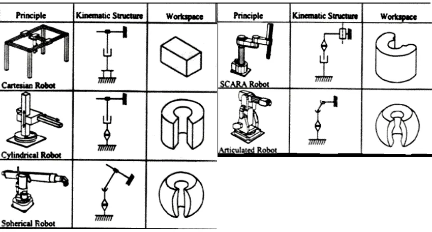
There are lots of robot types in this world. The main classification of robot includes; Cartesian Robot, Parallel Robot, Spherical Robot, Scara Robot, Cylindrical Robot, Articulated Robot and Mobile robot. Below are the definitions of every category (Types Of Robots, ROVer Ranch)[4]:-
a) Cartesian robot /Gantry robot: Used for pick and place work, application of sealant, assembly operations, handling machine tools and arc welding. It's a robot whose arm has three prismatic joints, whose axes are coincident with a Cartesian coordinator.
b) Cylindrical robot: Used for assembly operations, handling at machine tools, spot welding, and handling at diecasting machines. It's a robot whose axes form a cylindrical coordinate system.
c) Spherical/Polar robot: Used for handling at machine tools, spot welding, diecasting, fettling machines, gas welding and arc welding. It's a robot whose axes form a polar coordinate system.
d) SCARA robot: Used for pick and place work, application of sealant, assembly operations and handling machine tools. It's a robot which has two parallel rotary joints to provide compliance in a plane.
5
f) Parallel robot: One use is a mobile platform handling cockpit flight simulators. It's a robot whose arms have concurrent prismatic or rotary joints.
g) Mobile robot: have the capability to move around in their environment and are not fixed to one physical location. Mobile robot function is flexible and it is basically according to its creator research and focus in performing task.
[image:22.612.118.543.349.577.2]Figure 1.1 below shows the figure of five robot classification listed and discussed from seven which is; Cartesian robot, cylindrical robot, spherical robot, scara and articulated robot. The figure is consist with it kinematic structure and working space.
Figure 1.1 Robot classification; Cartesian, cylindrical, spherical, scara and articulated robot (Braz
6
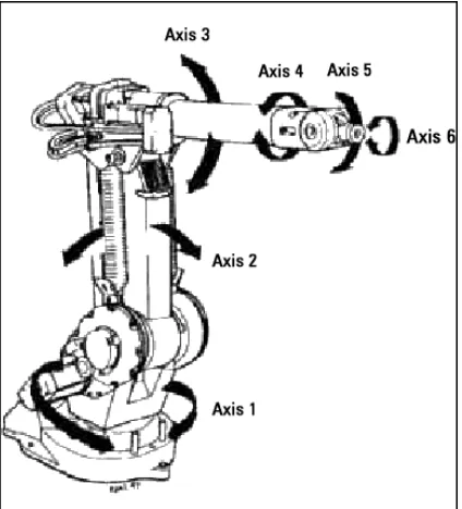
Figure 1.2 then show the image or parallel robot while 1.3 is a mobile robot.
[image:23.612.223.433.428.606.2]Figure 1.2 Articulated robot (Hyland 2001).
7
1.1.4 Application of Mobile Robot
Mobile robot can be described as a small robot that operated autonomously or manually controlled that can move at any environment profile given. Every mobile robot can be operated to do any task depending to its function and reason of its development. Mobile robot nowadays is widely used in order to perform any task that simple and repeated job or dangerous to human being such as a mobile robot for military used, for an example; the mine detection robot. Mobile robot is widely in use today in many sectors. In manufacturing industries as an example, mobile robot can be used as a part supplier from section to section. It will reduce manpower from supply parts and also will increase accuracy to supplying time. Because of mobile robot size is not over than human sizes and have capability to move around, human tend to use it as a service robot in certain area such as shopping complex for shopping guidance and hospital for nurses and doctor support service. Basically, mobile robot can be used in any sectors and its applications are wide as it can be design and built according to desire task.
1.1.5 Mobile Robot with Mecanum Wheels