City, University of London Institutional Repository
Citation:
Karcanias, N., Leventides, J. and Livada, M. (2014). Matrix pencil representation
of structural transformations of passive electrical networks. 6th International Symposium on
Communications, Control and Signal Processing (ISCCSP), pp. 416-420. doi:
10.1109/ISCCSP.2014.6877902
This is the accepted version of the paper.
This version of the publication may differ from the final published
version.
Permanent repository link:
http://openaccess.city.ac.uk/7279/
Link to published version:
http://dx.doi.org/10.1109/ISCCSP.2014.6877902
Copyright and reuse: City Research Online aims to make research
outputs of City, University of London available to a wider audience.
Copyright and Moral Rights remain with the author(s) and/or copyright
holders. URLs from City Research Online may be freely distributed and
linked to.
City Research Online:
http://openaccess.city.ac.uk/
[email protected]
MATRIX PENCIL REPRESENTATION OF STRUCTURAL TRANSFORMATIONS OF
PASSIVE ELECTRICAL NETWORKS
Nicos Karcanias, John Leventides and Maria Livada
Systems and Control Research Centre, School of Engineering and Mathematical Sciences,
City University London, Northampton Square, London EC1V 0HB,
[email protected]
ABSTRACT
The paper examines the problem of systems redesign within the context of passive electrical networks by considering the problem of multi-parameter and topology changes, and their representation. This representation may be used to investigate the impact of such changes on properties such as characteris-tic frequencies. The general problem area is the modelling of systems, whose structure is not fixed but evolves during the system life-cycle. The specific problem we are addressing is the study of effect of changing the topology of an electri-cal network that is changing individual elements of the net-work into elements of different type and value, augmenting / or eliminating parts of the network and developing a frame-work that allows the study of the effect of such transforma-tions on the natural frequencies. This problem is a special case of the more general network redesign problem. We use the Impedance-Admittance models and we establish a rep-resentation of the different types of transformations on such models. The representation of the structural transformations is given in terms of the companion pencil that preserves the natural topologies of the RLC network.
Index Terms— Systems Theory, Networks Theory
1. INTRODUCTION
The problem of redesigning autonomous (no inputs or out-puts) passive electric networks [1], [2] aims to change the network (natural frequencies) by modification of the types of elements, possibly their values, interconnection topology and possibly addition, or elimination of parts of the network. As such, this is a problem that differs considerably from a standard control problem, since it involves changing the sys-tem itself without control and aims to achieve the desirable system properties, as these may be expressed by the natural frequencies by system re-engineering. In fact, this problem involves the selection of alternative values for dynamic ele-ments (inductances, capacitances) and non-dynamic eleele-ments (resistances) within a fixed interconnection topology and/or alteration of the network interconnection topology and possi-ble evolution of the (increase of elements, branches). The aim
of the paper is to define an appropriate representation frame-work that allows the deployment of control theoretic tools for the re-engineering of properties of a given network when there are multi-parameter variations within a fixed, or variable cardinality network topology. We use impedance and admit-tance modelling [2], [3] for passive electrical networks and consider here systems with no sources (autonomous descrip-tions), since our current interest is on the shaping of natural frequencies. The emphasis here is on the study of the different representations of the passive network that enable the inves-tigation of the transformations on such models as structural transformations. The problem considered here is:
• Define the representation of changes of a many dy-namic, or non-dynamic elements with preservation, or alteration of existing topologies without changes in the overall nodal or loop cardinality of the network and define a framework for studying natural frequency assignment.
The overall aim is to explore the structure and representations of the Impedance-Admittance modelW(s)and introduce
2. PASSIVE NETWORK MODELS AND TOPOLOGIES
2.1. Impedance and Admittance Models
In the network loop analysis method, the variables are se-lected such that the vertex law is automatically satisfied. Here, we consider only planar graphs with b branches and n vertices. We then consider the variables associated with each of the meshes and we define them as loop variables. The overall system is reduced to a number of meshes, which are
[q = (b n + 1)[3],[9], referred to as loop cardinality of the network. If we denote by(f1, f2, ..., fq) the set of the
Laplace transforms of the loop currents and by(us1, ..., usq)
the set of Laplace transforms of equivalent voltage sources, then the loop or impedance model is defined by [10]:
Z(s)f(s) =us(s) (1)
where Z(s) has elements zii(s) expressing the sum of
impedances in loop i andzij(s) is the sum of impedances
common between loops i and j. This is known as the loop or impedance model and it is an integral-differential symmetric matrix andZ(s)is thenetwork impedance matrix.
Alternative modeling is the method using the across vari-ables from each vertex to some reference vertex. The number of vertex equations is in generalp= (n 1)and will be
re-ferred to asnodal cardinality of the network. If we denote by
(u1, u2, ..., un)the Laplace transforms of the node voltages
and by(is1, ..., isn)the set of Laplace transforms of
equiv-alent current sources, then the node or admittance model is defined by [2]:
Y(s)u(s) =is(s) (2) where: yii(s) is the sum of admittances in node i;yij(s) is the sum of admittances common between nodes i and j. This is referred to as the node or admittance model and it is an integral-differential symmetric matrix andY(s)is referred to
as thenetwork admittance matrix.
2.2. The Autonomous Natural Impedance-Admittance Model and Topologies
When we consider networks with no inputs (no current, or voltage sources) the resulting admittance, or impedance net-work models may be described in a unifying way as:
{pB+p 1C+D}x(t) = 0 (3)
wherep,p 1are respectively the differential, integral
op-erators respectively andx(t)is the vector of nodal voltages, or loop currents. Such a description may be referred to as the natural autonomous network description and the operator W(s) =sB+s 1C+Dwill be called the natural network
operator. Note that for the case of admittance we have that Bis a matrix of A-type elements (i.e. mass, inertance, ca-pacitance), C is the matrix of T-type elements (i.e. spring,
inductance) andDis a matrix of D type elements (i.e. re-sistance). For the case of impedance the reverse holds true. Hence, Bis the matrix of T-type elements,C is the matrix of A-type elements andDis the matrix of D-type elements. The symmetric operatorW(s)is thus a common description
ofY(s)andZ(s)matrices. The operatorW(s)describes the
dynamics of the network and of special interest are the prop-erties of its zeroes. Network modeling uses the system graph, which is the basic topological structure that generates the sys-tem equations. We may introduce some additional topologies, which are linked to the specifics of the Node and Loop analy-sis. The detailed topological structures that emerge depend on the nature of the elements in the network. The mass, inertia and capacitance store energy by virtue of their across- vari-ables (velocity, voltage) and they are referred to as A-type energy storage units [2]. Springs and inductances store en-ergy by virtue of their through- variables and are called T-type energy- storage devices. The dampers and resistances dissi-pate energy and will be called D-type elements.
2.2.1. The Vertex Topology
Every network may be represented in terms of a set of ver-tices, or nodes and all branches between two vertices may be represented by an admittance function. The nature of the el-ements in the branches of the natural vertex graph defines an element dependent topology, which is characterized by adja-cency type matrices. If we set the external sources to zero, the reduced graph will be referred to as the kernel vertex graph. For a given kernel vertex graph we define A-vertex sub-graph by eliminating from the kernel vertex graph all T- and D-type edges. Similarly, we define the T-vertex sub-graph by elim-inating all A- and D-type edges and the D-vertex sub-graph by eliminating all A- and T-type edges. The sub-graph of the natural vertex graph obtained by eliminating all T-, D-, A- type elements represents the location of the through vari-able sources and will be called the source-vertex sub-graph, or simply S-vertex sub-graph.
2.2.2. The loop topology
The loop topology is a notion dual to that of the vertex topol-ogy and it is based on the following principle: Every network of n vertices and b edges (branches) may be represented by q= (b n+ 1)loops leading to independent equations. All
3. THE LINEARISATION OF THE AUTONOMOUS NATURAL IMPEDANCE-ADMITTANCE MODEL
Starting from the integral-differential model of (3), described by the operatorW(s)the natural question that arises is how
we can transform it to an equivalent first-order, matrix pencil description, which preserves the topology of the network. We introduce a new set of variables,bx= [x,x˜]t,p 1x=exwhich
reduces (3) to a first order description given by equation (5) which has an associated matrix pencilsF+Gdefined by (6) and referred to as the network matrix pencil which is defined:
B 0
0 I
px px˜ =
D C
I 0
x
˜
x (4)
sF+G=
sB+D C
I sI (5)
Note that the above autonomous differential description pre-serves the topological properties of the network as these are represented by the B, C, D matrices, but its dimensionality is not necessarily minimal (dimensionality ofsF+G). The pencil derived is structured, but not symmetric in the general case and it will be referred to as thecompanion pencilof the network. The zeroes ofW(s)define the natural frequencies
of the network. Note that:
sB+D C I sI =s
k sB+s 1C+D
or
|sF+G|=sk.|W(s)|, W(s)2k⇥k(s) (6)
Remark (1):The non-zero natural frequencies of the network are given by the zeroes of the pencil and thus this pencil may be used for the study of assignment of natural frequencies under different types of transformations. For the special cases where the network is characterized only by A- and D- type elements or T- and D- type elements
f
W(s) =sB+D,cW(s) =bsC+D,bs=s 1 (7)
which are symmetric matrix pencils [5]. These pencils are derived from passive networks and thus inherit the passivity properties [4], [2].
4. NETWORK TRANSFORMATIONS
The general modeling for passive electrical networks provides a description of networks in terms of symmetric, integral, dif-ferential operator, W(s) = sB +s 1C +D. It is clear
that the network may be represented by the triple of matri-ces structural transformations{C, B, D}. The study of the structural changes on the network may be expressed as trans-formations on the matrices{C, B, D}. The general classes of structural transformations which may preserve, or alter the cardinality of the network, and may also change its different types of topology are defined below.
4.1. Classification of Structural Transformations
Type 1: Changing the values of the components of the sys-tem without changing the topology as this is described by
{C, B, D}tipple.
Type 2:Altering the nature of components by transformations on tipple without changing the element cardinality of the net-work.
Type 3: Modifying the networks topology and changing the
cardinality of elements by removing components / subsys-tems.
Type 4:Augmenting the networks topology and changing the cardinality of elements of the system by adding subsystems to the existing topology of the network. In the following we focus on Cases 1, 2 preserving the loop, or nodal cardinality and thus the dimensionality of{C, B, D}. These transforma-tions are then expressed as:
Definition 1:Given the triple of matrices{C, B, D}we con-sider transformations on the network matrices of the type
C0=C±c(x, b), B0=B±l(x, b), D0=D±r(x, b) (8) which preserve the physical elements cardinality (loop, or nodal cardinality) and depend on the real parameterx 2 < and the position vectorb2 <k. In fact, consider the changes
c(x, b),l(x, b),r(x, b) which have the general formf(x, b)
[4] where:
f(x, b) =xbbTforb=e
i, orb=ei ej,i6=j (9)
4.2. Examples
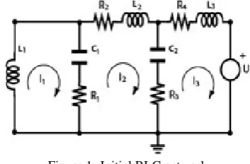
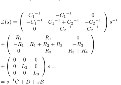
Consider the electrical network of Figure (1). The network variables are the loop currents I1, I2, I3. The impedance
[image:4.595.331.508.541.657.2]model expresses the impedances in the three loops and thus has the form of (9). We now assume that in this network we change the corresponding topology by adding the elements L4, R5, C3as shown in Figure (2).
Figure 1: Initial RLC network
Specifically the transformations are:
• Add a resistor to loop 1
• Add a capacitor to loop 2
Z(s) =
0 @
C1 1 C1 1 0
C1 1 C1 1+C2 1 C2 1
0 C2 1 C2 1
1 As 1
+
0
@ RR11 R1+RR21+R3 0R3
0 R3 R3+R4
1 A
+
0
@ 00 L02 00
0 0 L3
1 As=
=s 1C+D+sB
(10)
[image:5.595.67.275.126.271.2]Using the formulation (11) the above transformations can be expressed formally with modification to the corresponding matrices as shown below:
Figure 2: Augmented RLC network
(i) For the A-type elements:
C0=C+ 1
C3
b3bt3,whereb2=e2=⇥ 0 1 0 ⇤t (11) The above expresses the addition of capacitorC3to loop 2.
Hence, we have:
C0=
2 4 C1
1 C
1 1 0
C1 1 C1 1+C2 1 0
0 0 C3 1
3 5+
+C3 1
2
4 00 0 01 0
0 0 0
3 5=
=
2 4 C1
1 C
1 1 0
C1 1 C1 1+C2 1+C3 1 0
0 0 C3 1
3 5 (12)
(ii) For the D-type elements:
D0=D+R5b1b1t,whereb1=e1=
⇥
1 0 0 ⇤t (13) The above expresses the addition of resistorR3to loop 1.
Hence, we have:
D0=
2
4 RR11 R1+RR21+R3 0R3
0 R3 R3+R4
3 5+
+
2
4 R05 00 00
0 0 0
3 5=
=
2
4 R1+R1R5 R1+RR21+R3 0R3
0 R3 R3+R4
3
5 (14)
(iii) For the T-type elements:
B0=B+L4b12bt12,whereb12=e1 e2 (15)
The above expresses the addition of inductance to the branch common to loops 1 and 2. Hence, we have:
B0=B+L4
2
4 11 11 00
0 0 0
3 5=
2
4 L01 L02 00
0 0 L3
3 5+
+
2
4 LL44 LL44 00
0 0 0
3 5=
2
4 L1+L4L4 L2+L4L4 00
0 0 L3
3 5
(16) Summarizing, the transformed network is described by the corresponding matrices B0, C0, D0, which lead to the new impedance matrixW(s)describes the above transformations, is given by:Wf(s) =s 1C0+sB0+D0.
Remark (2): The presence of an element ofA , T , D type is expressed by an entry in the corresponding matrix C, B, T respectively. In specific:
• If an element is present in the ith loop (node), then its value is added in the ith position of the respective ma-trix.
• If an element is common to the ith and jth loop then its value is added to the ith and jth loop diagonal entries, as well as subtracted from the (i, j) and (j, i) position of the corresponding matrix.
Theorem (1):Consider a network described by the triple C, B, D with natural operatorW(s) =sB+s 1C+Dand
cor-responding companion pencilsF+G. Any network preserv-ing cardinality transformation (combination of Type 1 and 2) may be represented by a triple{C⇤, B⇤, D⇤}and it results in a companion pencilsF0+G0defined by:
sF0+G0=sF+G+
sB⇤+D⇤ C⇤
0 0
= (sF+G) + (sH+K) (17)
5. CONCLUSIONS
The paper has examined the problem of redesign of passive electric networks as a problem describing the structure evo-lution of systems linked to changes in the nature of topology, and values of the physical elements. Four different types of structural transformations have been defined and for the two which preserve the network cardinality it has been shown that these transformations are expressed as additive structured transformations on the companion pencil. The assignment of natural frequencies of the network may then be formulated as a spectrum assignment of matrix pencils under additive transformations and may be studied within the framework of Determinantal Assignment introduced in [6], [7]. Amongst the problems under investigation is the study of spectrum assignment under special families of (H,K) transformations, the characterization of the fixed frequencies (if any) and the derivation of conditions for arbitrary assignment of such frequencies.
6. REFERENCES
[1] N. Karcanias, “Structure evolving systems and control in integrated design,”Annual reviews in Control, 2008.
[2] N. Karcanias, “Passive network redesign: System struc-ture evolution,” Tech. Rep., City University London, 2011.
[3] S. Seshu and M. Reed, Linear Graphs and Electrical networks, Addison- Wesley, 1961.
[4] N. Karcanias T. Berger, G. Halikias, “Effects of dy-namic and non-dydy-namic element changes in rlc net-works,” International Journal of Circuit Theory and Applications, 2014.
[5] Leventides J. and Karcanias N., “Zero assignment of matrix pencils by additive structured transformations,”
Linear Algebra and its Applications, vol. 431, no. 8, pp. 1380–1396, 2009.
[6] N. Karcanias and C. Giannakopoulos, “Grassmann in-variants, almost zeros and the determinantal zero and pole assignment problem,” Int. J. Control, 1984.
[7] J.Leventides and N.Karcanias, “Global asymptotic lin-earisation of the pole placement map: A closed form solution for the constant output feedback problem,” Au-tomatica, vol. 31, no. 9, pp. 1303–1309, 1995.
[8] B. Laios N. Karcanias and C. Giannakopoulos, “The decentralised determinantal assignment problem: Fixed and almost modes and zeros,” Int. J. Control, vol. 48, pp. 129–147, 1988.
[9] F R. Gantmacher,The Theory of Matrices, vol. I and II, Chelsea, New York, 1959.