Performance Analysis of Iteratively Decoded
Variable-Length Space-Time Coded Modulation
S. X. Ng1, W. Liu1, J. Wang1, M. Tao2, L.-L. Yang1 and L. Hanzo1 1School of ECS, University of Southampton, SO17 1BJ, United Kingdom.
Email:{sxn,wl03r,jw02r,lly,lh}@ecs.soton.ac.uk, http://www-mobile.ecs.soton.ac.uk
2Department of Electrical and Computer Engineering, National University of Singapore, Singapore 117576.
Email: [email protected]
Abstract— It is demonstrated that iteratively Decoded Variable Length Space Time Coded Modulation (VL-STCM-ID) schemes are capable of simultaneously providing both coding gain as well as multiplexing and diversity gain. The VL-STCM-ID arrangement is a jointly designed iteratively decoded scheme combining source coding, channel coding, modulation as well as spatial diversity/multiplexing. In this contribution, we analyse the iterative decoding convergence of the VL-STCM-ID scheme using symbol-based three-dimensional EXIT charts. The performance of the VL-STCM-ID scheme is shown to be about 14.6 dB better than that of the Fixed Length STCM (FL-STCM) benchmarker at a source symbol error ratio of 10−4, when communicating over uncorrelated Rayleigh fading channels. The performance of the VL-STCM-ID scheme when communicating over correlated Rayleigh fading channels using imperfect channel state informa-tion is also studied.
I. INTRODUCTION
Shannon’s separation theorem stated that source coding and channel coding is best carried out in isolation [1]. However, this theorem was formulated in the context of potentially infinite-delay, lossless entropy-coding and infinite block length channel coding. In practice, real-time wireless audio/video communications systems do not meet these ideal hypotheses. Specifically, the source encoded symbols often remain corre-lated, despite the lossy source encoder’s efforts to remove all redundancy. Furthermore, they exhibit unequal error sensitiv-ity. In these circumstances, it is often more efficient to use jointly designed source and channel encoders.
Space-time coding schemes, which employ multiple trans-mitters and receivers, are among the most efficient techniques designed for providing high data rates, which are capable of exploiting the high channel capacity potential of Multiple-Input Multiple-Output (MIMO) channels [2]. More explicitly, Bell-lab’s LAyered Space Time architecture (BLAST) [3] was designed for providing full-spatial-multiplexing gain, while Space Time Trellis Codes (STTC) [4] were designed for providing full-spatial-diversity gain.
A jointly designed source coding and Space Time Coded Modulation (STCM) scheme has been proposed in [5], [6]. This scheme employs novel two dimensional (2D) Variable Length Codes (VLCs) and is capable of exploiting both spatial and temporal domain diversity. More specifically, the number of activated transmit antennas equals the number of non-zero-energy symbols of the corresponding VLC codeword in
The financial support of the European Union under the auspices of the Newcom and Phoenix projects, as well as that of the EPSRC UK is gratefully acknowledged.
the spatial domain, where each VLC codeword is transmitted during a single symbol period. Hence, the transmission frame length is determined by a fixed number of source symbols and therefore the proposed Variable Length STCM (VL-STCM) scheme does not incur synchronisation problems and does not require the transmission of side information. Additionally, the associated source correlation is converted into an increased minimum product distance [5], which leads to an increased coding gain.
For the sake of attaining additional iteration gains, the VL-STCM scheme was further developed in [7] by introducing parallel non-binary Unity-Rate Codes (URCs) between the variable-length space-time encoder and the modulator. The Iteratively Decoded (ID) VL-STCM (VL-STCM-ID) scheme achieves a significant coding/iteration gain over both the non-iterative VL-STCM scheme and the Fixed Length STCM (FL-STCM) benchmarker [7]. The decoding convergence of the VL-STCM-ID scheme will be analysed and its performance using imperfect channel state information will be studied in this contribution.
II. VL-STCM OVERVIEW
Consider for example a source having Ns = 8 possible
discrete values and let the lth value be represented by a symbol sl = l for l ∈ {1,2, . . . , N
s}. We assume that the
source symbols emitted are independent of each other and have unequal probabilities of occurrence given by
P(sl+1) = 0.6P(sl) = 0.6lP(s1), (1)
and Ns
l=1P(sl) = 1. Note that a source is correlated when its entropy rate H(s) is smaller than log2(Ns) [8].
For the independent source considered, the source entropy rate equals the source entropy H(s), which is given by: H(s) = H(s) = −8l=1log2(P(sl))·P(sl) = 2.302 bit. SinceH(s)<log2(Ns), the source considered is a correlated
source, where the higher the source correlation the smaller the source entropy rate. Let us now consider a 2D VLC which encodes theseNs= 8possible source symbols usingNt= 3
transmit antennas and BPSK modulation. The codebook can be formulated as a matrix:
VV LC =
xx 1x x0 0x x1 1 0 10 1 1
0 x x 1 1 x 1 0
, (2)
f
(1) =
−
A
f
(x) = 0
f
(0) =
A
−
A
0
A
A
=
Nt [image:2.595.53.289.64.281.2]Lave
Fig. 1. The signal mapper of the VL-STCM.
Mapper Mapper
Mapper
Mapper Modulator VL−STC Encoder
Encoder
2D VLC S1
S2 s[t]
Sp−q
S3
Sp
p=Nt
j=1(j−1) ; q=Nt−2
vNt[t] v3[t]
v2[t]
v1[t] c1[t] c2[t] c3[t]
cNt[t]
x1[t] x2[t] x3[t]
xNt[t]
Fig. 2. Block diagram of the VL-STCM transmitter.
entry denoted as 0 and 1 represents the BPSK symbols to be transmitted, while ‘x’ corresponds to ‘no transmission’. ‘No transmission’ implies that the corresponding transmit antenna sends no signal. Let the lth source symbol sl be encoded
using thelth column of theVV LC matrix seen in Equation 2.
Hence, the source symbols1 is encoded into an Nt-element
codeword using the first column of VV LC in Equation 2,
namely[x x0]T, where the first and second transmit antennas
are in the ‘no transmission’ mode, while the third antenna transmits an ‘active’ symbol represented by the binary value ‘0’. LetL(sl)be the number of ‘active’ symbols in the VLC
codeword assigned to source symbol sl, then we may define
the average codeword length of the 2D VLC as:
Lave= Ns
l=1
P(sl)L(sl), (3) where we have Lave = 1.233 bit/VLC codeword for this
system according to Equations 1 and 2. The corresponding BPSK signal mapper is characterised in Figure 1, where the ‘no transmission’ symbol is actually represented by the origin of the Euclidean space, i.e. we havef(x) = 0, wheref(.)is the mapping function. Since the ‘no transmission’ symbol is a zero energy symbol, the amount of energy saving can be computed from:
A2= Nt Lave ,
(4)
where we have A2 = 3/1.233 = 2.433, which is equivalent to 20 log(A) = 3.86 dB. Hence, more transmitted energy is saved, when there are more ‘no transmission’ symbols in a VLC codeword. As a result, one can assign the more frequently occurring source symbols to the VLC codewords having more ‘no transmission’ components, in order to save transmit energy. The energy saved is then reallocated to the ‘active’ symbols for the sake of increasing their minimum Euclidean distance, as shown in Figure 1.
The 2D VLC matrix seen in Equation 2 was designed in [7], where Nt = 3 transmit antennas were employed for
transmitting the Nt-element 2D VLC codewords denoted as
v = [v1. . . vNt]T in Figure 2. It was shown in [7] that it
attains a transmitter-diversity order quantified by the minimum Hamming distance of 2, a coding gain quantified by the minimum product distance of5.92and a spatial multiplexing gain quantified by log2(Ns/M) = 2, where M = 2 is the
number of modulation levels of the original BPSK modulation andNs= 8is the number of source symbols. The throughput
of the scheme is given byη= log2(Ns) = 3bit/s/Hz and the
Signal to Noise Ratio (SNR) per bit is given byEb/N0=γ/η,
whereγ is the SNR per receive antenna.
The block diagram of the VL-STCM transmitter is illus-trated in Figure 2, which can be represented by two funda-mental blocks, namely the Variable Length Space Time Code (VL-STC) encoder and the modulator. As seen in Figure 2, a VLC codewordv[t] = [v1[t]v2[t]. . . vNt[t]]T is assigned to
each of the source symbolss[t]generated by the source at time instantt, where we have s[t]∈ {1, . . . , Ns}andNs denotes
the number of possible source symbols. Each of the VLC code-wordsv[t]seen in Figure 2 corresponds to one of the matrix columns in in Equation 2. As portrayed in Figure 2, the VLC codewordv[t]is transmitted diagonally across the space-time grid with the aid of shift registers denoted asSk in Figure 2,
where we havek∈ {1,2, . . . ,Nt
j=1(j−1)}. As we can see from Figure 2, the codewordv[t] = [v1[t]v2[t] . . . vNt[t]]T is
transmitted usingNttransmit antennas, where themth element
of each VLC codeword, for 1 ≤ m ≤ Nt, is delayed by
(m−1) shift register cells, before it is transmitted through the mth transmit antenna. Hence, theNt number of components
of each VLC codeword are transmitted on a diagonal of the space-time codeword matrix [5], [7].
III. VL-STCM-ID OVERVIEW
Mapper
Mapper Mapper
Encoder 2D−VLC
D
D
D
D v1[t]
D v2[t]
D v3[t]
x1[t]
x2[t]
x3[t]
c1[t]
c2[t]
c3[t]
VL-STC Encoder Modulator
πs
πs
πs
u1[t]
u2[t]
u3[t]
[image:2.595.301.539.480.573.2]s[t]
Fig. 3. The VL-STCM-ID transmitter employing Nt = 3transmit and
Nr= 2receive antennas, whereπsdenotes symbol interleaver.
In order to invoke iterative detection and hence attain iteration gains as a benefit of the more meritoriously spread extrinsicinformation, a symbol-based random interleaver and a non-binary URC were introduced for each of theNt = 3
transmit antennas [7]. The Nt = 3 parallel symbol-based
interleavers were generated independently. As we can see from Figure 3, the sequence corresponding to all themth elements in the space-time codeword{cm[t]},m∈ {1,2,3}, is further
interleaved and encoded by a non-binary URC, before being fed to the mapper and transmitted as{xm[t]}. The non-binary
number of distinct symbols in the VLC space-time codeword and we havecm[t]∈ {0,1,x}. Note that we represent the ‘x’
symbol using the number ‘2’ during the modulo-M¯ addition.
VL−STC
MAP
Decoder (3) Demodulator
Demapper Soft
(1) (2.1)
−
− MAP
Decoder
Decoder MAP
πs
π−1
s
ˆ s[t] πs
π−1
s
...
L1.1
e (u) L3a.1(c)
L0.1
a(c)
L2.1
e (c)
yNr[t]
y1[t]
˜ c1[t] ˜
u1[t]
L2.1
e (u) L2a.1(c)
L0.1
a(c)
L3.1
e (c)
... ...
(2.Nt) ˜
[image:3.595.55.289.115.216.2]uNt[t] ˜cNt[t]
Fig. 4. The VL-STCM-ID receiver for anNr×NtMIMO system. The
notation(˜.) and(ˆ.)indicates theextrinsic/a prioriprobability and the hard decision estimate of(.), respectively. The notationLi.m(a,e)(c, u)denotes
the log-domain symbol probability of the VL-STC codewordcor the URC
codeword u for the mth transmitter. The subscripts a and e denote the
a prioriandextrinsicnature of the probabilities while the superscripti.m
identifies that the probabilities belong to theith stage decoder for themth
transmitter. Note thati= 0means that the probabilities were calculated from
the source symbol distribution.
At the receiver, the symbol-based log-domain MAP algo-rithm [9] is used by both the VL-STC decoder and the URC decoder. The block diagram of the VL-STCM-ID receiver is depicted in Figure 4, where we denote the log-domain symbol probability of the VL-STC codeword cm and the
URC codewordum for the mth transmitter as Li.m(a,e)(c)and Li.m(a,e)(u), respectively. Furthermore, the subscripts a and e denote thea prioriandextrinsicnature of the probabilities, while the superscripti.msuggests that the probabilities belong to theith decoder stage of themth transmitter. Note thati= 0 implies that the probabilities were calculated from the source symbol distribution. The extrinsic probability of the URC codeword of transmit antennam, namely Pe(um[t]), can be
computed during each symbol period in the ‘Soft Demapper’ block of Figure 4. By dropping the time-related square bracket, we can computePe(um)as:
Pe(um=b) =
x∈χ(m,b)
P(y|x)
allj
∀j=m
Pa(uj)
, (5)
m∈ {1,2, . . . , Nt}, b∈ {0,1,x}
where the subsetχ(m, b)contains all the phasor combinations for the transmitted signal vector x = [x1 x2 . . . xNt]T
with xm = f(um = b), while P(y|x) is the conditional
Probability Density Function (PDF) of the received signal. When communicating over Rayleigh fading MIMO channels, we have:
P(y|x) =
1
2πσn2
Nr
exp
−||y−Hx||2
2σn2
, (6)
whereσn2=N0/2is the noise variance,yis theNr-element
complex received signal vector and H is the (Nr × Nt
)-dimensional complex channel matrix during the time instant t. Furthermore, thea prioriprobability ofum in Equation 5
is computed from theextrinsiclog-domain probability of the mth URC MAP decoder as Pa(um) = exp(L2e.m(u)), while
the log-domaina prioriprobability ofumfor themth URC
MAP decoder is given by L1.m
e (u) = ln(Pe(um)).
It is possible to attain some a priori probability for the Nt-element VL-STC codewords, c, (which also constitute
the URC’s input words), given the source symbol occurrence probability specified in Equation 1. Explicitly, the probability of the mth URC’s input wordcm can be expressed as:
P(cm=d) =
l∈µ(m,d)
P(sl), (7)
m∈ {1,2, . . . , Nt}, d∈ {0,1,x},
where the subsetµ(m, d)contains the specific indices of those columns in the VLC matrix, where the mth row element in that column equalsd. Hence, we haveL0.m
a (c) = ln(P(cm))
as an additional a priori probability for symbol cm during
each iteration between the URC MAP decoder and the VL-STC MAP decoder, as shown in Figure 4. Note that P(cm)
is directly computed from the source symbol occurrence probability P(sl), hence we do not use P(sl) again as the
a prioriprobability of the VL-STC input word in the VL-STC MAP decoder, in order to avoid reusing the same information. A full iteration consists of a soft demapper operation,Nt=
3URC MAP decoder operations and a VL-STC MAP decoder operation. For the non-iteratively decoded VL-STCM/FL-STCM, the soft demapper computes thea prioriinformation of c[t] = [c1[t] c2[t]c3[t]]T and feeds it to the
STC/FL-STCM MAP decoder. Note that the MAP decoder of VL-STCM/FL-STCM also benefits from the a prioriprobability of its input words[t]. Hence, as the source becomes correlated, the VL-STCM-ID, VL-STCM and FL-STCM schemes will benefit from the a priori probability of the source symbols. However, FL-STCM attains no energy savings.
IV. CONVERGENCEANALYSIS
Extrinsic Information Transfer (EXIT) charts designed for binary receivers [10] have been widely used for analysing the convergence behaviour of iterative decoding aided con-catenated coding schemes. In this paper, we will employ the technique proposed in [11] for computing thenon-binary EXIT functions. However, the convergence analysis of the proposed three-stage VL-STCM-ID scheme requires the employment of novel three Dimensional (3D) non-binary EXIT charts, which evolved from the binary 3D EXIT charts used in [12] for analysing multiple concatenated codes.
To elaborate a little further, EXIT charts visualise the input and output characteristics of the constituent MAP decoders in terms of the mutual information transfer between the input sequence and the a priori information at the input, as well as between the input sequence and theextrinsicinformation at the output of the constituent decoder. Hence, there are two steps in generating an EXIT chart. Firstly, we have to model thea prioriprobabilities of the input sequence and then feed them to the decoder. Secondly, we have to compute the mutual information of theextrinsicprobabilities at the output of the decoder. Let us now model thea priori probabilities of the VL-STC codeword, c = [c1 c2 . . . cNt]T, where cm,m ∈
Let us denote the input symbol of the mth URC as c, where the subscriptm is omitted for simplicity. Assume that the symbol c is transmitted over an AWGN channel using the M= 3-phasor mapper shown in Figure 1. The received signal is given byy = x+n, where nis the AWGN noise having a zero mean and a variance of ¯σ2n. Furthermore, we
[image:4.595.54.287.206.436.2]havex=f(c), wheref(.)is the mapper function portrayed in Figure 1. Sincef(.)is a memoryless function, the probability of occurrence forx is the same as that ofc. Hence, we have P(x) =P(c), which is expressed in Equation 7. At a given set of occurence probabilities forx, the mutual information betweenxandy can be formulated as:
I(x;y) =
M
i=1
y
P(xi, y) log2
P(xi, y)
P(xi)P(y)
dy,
= H(x)−H(x|y), (8) whereH(x)is the entropy ofx, given by:
H(x) = −
M
i=1
P(xi) log2(P(xi)), (9)
andH(x|y)is the conditional entropy ofxgiveny, which can be expressed as:
H(x|y) =
M
i=1
P(xi)E
log2
M
j=1
P(xj)
P(xi)
exp(Ψi,j)
.(10)
In Equation 10, we haveexp(Ψi,j) =P(y|xj)/P(y|xi)and
P(y|x)is the conditional Gaussian PDF, while the exponent
Ψi,j is given by:
Ψi,j =−|xi−xj
+n|2+|n|2
2¯σ2n
. (11)
The expectation term E[.] in Equation 10 is taken over the AWGNn. Hence, a curve can be generated forI(x;y)versus
¯
σ2n, where the expectation term in Equation 10 is evaluated
using Monte Carlo simulation. We can simplify Equation 8 to a form, whereI(x;y) is expressed as a function ofσ¯n2. Let
us denote this function asJ(.)and we haveI(x;y) =J(¯σn2).
Note thatI(x;y)is monotonically decreasing with respect to
¯
σ2n.
Let us now denote thea prioriinformation ofcasIA(c) =
I(x;y). At a given IA value we can find the corresponding
noise variance with the aid of the inverse function σ¯2n =
J−1(IA(c)) using the I(x;y) versus σ¯n2 curve. Then we
can generate a noise sample n having a variance of σ¯n2.
Consequently, we can produce y = x+n, where again x=f(c)represents the mapper function portrayed in Figure 1 andcis the actual input symbol of themth URC. Finally, we can generate thea priorisymbol probabilities forPa(c)using
the conditional Gaussian PDF:
Pa(c) =
1 2πσ¯n2
exp
−|y−f(c)|2
2¯σ2n
, (12)
forc∈ {0,1,x}. Then we feed these symbol probabilities to the corresponding MAP decoder. Note that the above method can be used for any symbol-interleaved serially concatenated coding schemes, where the symbol probabilities are directly
created for a givenIAvalue. The mutual information for the
Nt-element VL-STC codewordc = [c1 c2 . . . cNt]T is the
sum of the mutual information valid for its symbol components cm, expressed as IA(c) =
Nt
m=1IA(cm), where IA(cm) is
the mutual information of themth symbol component of the VL-STC codeword or themth URC’s input symbol, given by Equation 8. Note that the maximum value ofIA(cm)equals
the entropy ofcm given by Equation 9.
Next, we compute the mutual information of theextrinsic symbol probabilitiesIE(cm)at the output of the VL-STC or
URC decoder for the symbolcmusing the method proposed in
[11]. Finally, the mutual information of theextrinsicsymbol probabilities for the VL-STC codeword can be computed fromIE(c) =
Nt
m=1IE(cm). We also compute the mutual
information for the URC codeword u based on the same procedure.
0
1.5613
3.1226
4.6839
x: IEi(URC), IA(VL-STC)
0 1.5613 3.1226 4.6839
y: IE(VL-STC), IA
i (URC) 0 1.585 3.17 4.755
z: IE(Demap), IA
o (URC)
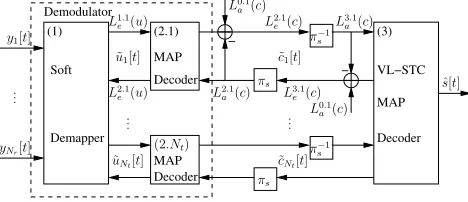
Fig. 5. The 3D EXIT charts for the VL-STCM-ID scheme havingNt= 3
andNr= 2, when using an uncorrelated source. The iterative trajectory is
computed atEb/N0 = 4dB. The maximum value of an axis denotes the
entropy of the corresponding symbol.
The 3D EXIT charts and the actual iterative decoding trajectories for the VL-STCM-ID scheme havingNt= 3and
Nr = 2 are shown in Figure 5 for an uncorrelated source.
Let us denote the three axes of the 3D EXIT charts using the letters x, y and z, whileIA(*) andIE(*) denote thea priori
andextrinsic information for (*), respectively, where (*) is either the VL-STC MAP decoder (VL-STC) or the URC MAP decoder (URC) or, alternatively, the soft demapper (Demod). As we can see from Figure 4, each of the URC MAP decoders takes (provides) the a priori (extrinsic) probabilities of its input word c and output word (or codeword) u as the input (output). Hence, the mutual information of the input word and output word of the URC decoder will be represented by Ii
(A,E)(URC) andI(oA,E)(URC), respectively. Each of the Nt
symbol interleavers shown in Figures 3 has a length of 10000 symbols.
[image:4.595.311.515.260.427.2]2dprojections.gle
0.0 1.56 3.12 4.68
IE(VL-STC), IA i
(URC), IA(Demod)
0.0 1.56 3.12 4.68
IA
(VL-STC),
IE i (URC),
IE
(Demod)
..
..
..
..
. .
. .
. .
. .
. .
. .
. .
. .
. .
Demod URC
.
VL-STCFig. 6. The 2D EXIT charts projection for the VL-STCM-ID scheme having
Nt= 3andNr= 2, when using an uncorrelated source atEb/N0= 4dB.
The maximum value of an axis denotes the entropy of the corresponding symbol.
the URC decoder and the VL-STC decoder. Hence, by project-ing these two convergence curves onto z=0 in Figure 5 gives us the equivalent 2D EXIT chart seen in Figure 6. Therefore, the 3D EXIT charts generated for multiple concatenated codes can be projected onto an equivalent 2D EXIT chart [12].
More specifically, we can observe an open tunnel between the EXIT curves of the VL-STC and URC schemes in the 2D EXIT charts of Figure 6 at Eb/N0= 4 dB, which indicates
that decoding convergence can be achieved. Note that the EXIT curve generated for the soft demapper is also depicted in Figure 6 atEb/N0= 4dB. This curve is almost flat and it
intersects with the VL-STC EXIT curve, before the maximum value of 4.68 bits is reached. Hence, decoding convergence cannot be achieved atEb/N0= 4dB when the URC was not
invoked between the soft demapper and the VL-STC.
0
1.2887
2.5774
3.8661
x: IEi(URC), IA(VL-STC)
0 1.2887 2.5774 3.8661
y: IE(VL-STC), IA
i (URC) 0 1.585 3.17 4.755
z: IE(Demap), IA
[image:5.595.55.291.69.230.2]o(URC)
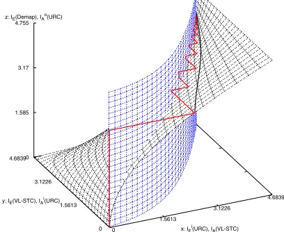
Fig. 7. The 3D EXIT charts for the VL-STCM-ID scheme havingNt= 3
andNr= 2, when using the correlated source defined in Equation 1. The
iterative trajectory is computed atEb/N0= 3dB. The maximum value of
an axis denotes the entropy of the corresponding symbol.
Figure 7 shows the 3D EXIT charts and the corresponding convergence curve of the soft demapper and the URC decoder as well as the actual iterative decoding trajectory for the VL-STCM-ID scheme having Nt = 3 and Nr = 2 when using
the correlated source defined in Equation 1. As the source becomes correlated, the entropy of the codewordcmform∈
{1,2,3}reduces. Hence, the maximum values for the x and y axes in Figure 7 are smaller than those in Figure 5. However, the open spatial segment of the 3D space between the two EXIT planes becomes wider, since the decoders exploit the additionala priori probabilities given by Equation 7, when the source is correlated. The convergence curve of the soft demapper and the URC decoder is projected as a dashed line ontoIE(Demod)=0 in Figure 7. Similarly, the projection of the
intersection line between the VL-STC and URC EXIT planes is represented by the curve lying on the vertical EXIT plane at IE(Demod)=0. As can be seen from Figure 7 atIE(Demod)=0,
an open tunnel exists between the two projection curves at Eb/N0 = 3 dB. Hence, the iterative decoder converged at
Eb/N0= 3dB, i.e. at a 1 dB lower value, when employing
the correlated source instead of the uncorrelated source. According to the MIMO channel capacity formula derived for the Discrete-Input Continuous-Output Memoryless Chan-nel (DCMC) in [13], the DCMC capacity for theNr= 2and
Nt = 3 MIMO scheme employing the signal mapper seen
in Figure 1 is Eb/N0 = 1.25 dB at a bandwidth efficiency
of 3 bit/s/Hz. Hence, the performance of the VL-STCM-ID schemes in Figures 5 and 7 is about 2.75 dB and 1.75 dB away from the MIMO channel capacity.
V. SIMULATION RESULTS
The Fixed Length (FL) STCM (FL-STCM) scheme used in [7] employed the following FL Codebook (FLC) matrix:
VF LC =
0 0 0 0 1 1 1 10 0 1 1 0 0 1 1 0 1 0 1 0 1 0 1
. (13)
The FL-STCM transmitter obeys the schematic of Figure 2, except that it employs theVF LCof Equation 13. For the
FL-STCM, the minimum Hamming distance and product distance are 1 and 4, respectively. It attains the same multiplexing gain as that of the VL-STCM or VL-STCM-ID arrangements. Note that it is possible to create an iterative FL-STCM-ID scheme by replacing the VL-STC encoder in Figure 3 with the FL-STC encoder. However, the EXIT curve of the FL-FL-STC scheme of Equation 13 was found to be too flat for attaining any iteration gain due to its unity minimum Hamming distance. Let us now evaluate the performance of the STCM, VL-STCM-ID and FL-STCM schemes in terms of their source Symbol Error Ratio (SER) versus theEb/N0ratio. Again we
haveEb/N0=γ/η, whereγ is the SNR per receive antenna
andη = log2(Ns) = 3 bit/s/Hz is the effective information
throughput. Throughout our simulations, we use three transmit antennas and two receive antennas. The interleaver length is set to 10000 symbols.
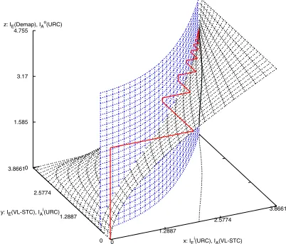
Figure 8 depicts the SER versus Eb/N0 performance of
[image:5.595.64.265.467.639.2]stvlc-id2psk-ser-itercwapr-no-dwapr.gle
0 2 4 6 8 10 12 14 16 18 20
Eb/N0(dB)
10-5 10-4 10-3 10-2 10-1 1
SER
Correlated source:
Uncorrelated source: FL-STCM VL-STCM VL-STCM-ID
FL-STCM VL-STCM VL-STCM-ID 1 iter.
8 iter.
14.6 dB Capacity
[image:6.595.53.289.67.228.2]Limit
Fig. 8. SER versus Eb/N0 performance of the VL-STCM,
VL-STCM-ID and FL-STCM schemes, when communicating over uncorrelated Rayleigh
fading channels using BPSK,Nt= 3andNr= 2.
as the source becomes correlated. On the other hand, the coding gain attained as a benefit of transmitting correlated source symbols increases, as the number of iterations invoked by the VL-STCM-ID scheme increases. The performance of VL-STCM-ID at SER= 10−4 after the 8th iteration is approximately 6.5 (15) dB and 7.5 (14.6) dB better than that of the VL-STCM (FL-STCM) scheme, when employing correlated and uncorrelated sources, respectively.
stvlc-chan-est-wiener-2.gle
0 2 4 6 8 10 12 14 16 18 20
Eb/N0(dB)
10-5 10-4 10-3 10-2 10-1 1
SER
Imperfect CSI with Pilot spacing of:
Perfect CSI
200 sym. 500 sym. 2500 sym. 1 iter.
[image:6.595.53.288.376.538.2]8 iter.
Fig. 9. SER versus Eb/N0 performance of the VL-STCM,
VL-STCM-ID and FL-STCM schemes, when communicating over correlated Rayleigh
fading channels at a normalised Doppler frequency of10−4, using Wiener
filter based channel estimation, BPSK,Nt= 3andNr= 2.
Figure 9 shows the SER versusEb/N0performance of the
VL-STCM-ID scheme, when communicating over correlated Rayleigh fading channels at a normalised Doppler frequency of10−4and using Wiener filter based channel estimation [14]. The source is correlated, as formulated in Equation 1. As we can see from Figure 9, when the Channel State Information (CSI) becomes more accurate as a benefit of using a shorter pilot symbol spacing, the performance of the VL-STCM-ID approaches that of the ideal case with perfect CSI. When using a pilot spacing of 200 symbols, there are10000/200 = 50 sub-frames within the 10000-symbol frame. Note thatNt frames
are transmitted in parallel fromNt transmit antennas in order
to convey a space-time coded frame in the MIMO system.
In order to detect the channel coefficients from each transmit antenna,Ntnumber of orthogonal pilot sequences are inserted
at the end of the Nt sub-frames transmitted in parallel. We
need a minimum of Nt pilot symbols for each of the pilot
sequences in order to constructNtorthogonal pilot sequences.
Hence, when using a pilot spacing of 200 symbols,Nt = 3
pilot symbols are inserted for every 200 VL-STCM-ID coded symbols, which corresponds to a transmission overhead of
3/200 = 1.5% and requires inserting(10000×Nt/200) = 150
pilot symbols into the transmission frame of10000 + 150 =
10150symbols.
VI. CONCLUSIONS
The convergence properties of the VL-STCM-ID scheme were analysed using EXIT charts. A significant iteration gain was achieved by the VL-STCM-ID scheme, which hence outperformed both the non-iterative VL-STCM scheme as well as the FL-STCM benchmarker with the aid ofNt number of
unity-rate recursive precoders. The near capacity performance of VL-STCM-ID scheme is retained, when employing a real-istic Wiener filter based channel estimator, rather than using perfect channel estimation.
REFERENCES
[1] C. Shannon, Mathematical Theory of Communication. University of
Illinois Press, 1963.
[2] E. Telatar, “Capacity of multi-antenna Gaussian channels,”European
Transactions on Telecommunication, vol. 10, pp. 585–595, Nov–Dec 1999.
[3] G. J. Foschini, Jr., “Layered space-time architecture for wireless commu-nication in a fading environment when using multi-element antennas,”
Bell Labs Technical Journal, pp. 41–59, 1996.
[4] V. Tarokh, N. Seshadri and A. R. Calderbank, “Space-time codes for high rate wireless communication: Performance analysis and code
construc-tion,”IEEE Transactions on Information Theory, vol. 44, pp. 744–765,
March 1998.
[5] S. X. Ng, J. Wang, L.-L. Yang and L. Hanzo, “Variable Length Space
Time Coded Modulation,” inIEEE Vehicular Technology Conference,
(Dallas, Texas), pp. 1049–1053, 25-28 September 2005.
[6] M. Tao and S. X. Ng, “Space Time Variable Length Coding for
Wire-less Multimedia Communications,” inProceedings of 3rd International
Conference on Communications, Circuits and Systems (ICCCAS), (Hong Kong, China), pp. 51–55, 27-30 May 2005.
[7] S. X. Ng and L. Hanzo, “Iteratively Decoded Variable Length Space
Time Coded Modulation,” inProceedings of IEE International
Sympo-sium on Communication Theory & Applications (ISCTA), (Ambleside, Lake District, UK), pp. 309–314, 17 - 22 July 2005.
[8] T. M. Cover and J. A. Thomas,Elements of Information Theory. New
York, USA: John Wiley IEEE Press, 1991.
[9] L. Hanzo, T. H. Liew and B. L. Yeap,Turbo Coding, Turbo Equalisation
and Space Time Coding for Transmission over Wireless channels. New York, USA: John Wiley IEEE Press, 2002.
[10] S. ten Brink, “Convergence behaviour of iteratively decoded parallel
concatenated codes,”IEEE Transactions on Communications, vol. 49,
pp. 1727–1737, October 2001.
[11] J. Kliewer, S. X. Ng and L. Hanzo, “On the computation of EXIT
characteristics for symbol-based iterative decoding,” in4th International
Symposium on Turbo Codes in connection with 6th International ITG-Conference on Source and Channel Coding, (Munich, Germany), 3-7 April 2006.
[12] F. Brannstrom, L. K. Rasmussen and A. J. Grant, “Convergence analysis
and optimal scheduling for multiple concatenated codes,”IEEE
Trans-action on Information Theory, pp. 3354–3364, Sept 2005.
[13] S. X. Ng and Hanzo, “On the MIMO Channel Capacity of
Multi-Dimensional Signal Sets,”IEEE Transactions on Vehicular Technology,
vol. 55, pp. 528–536, March 2006.
[14] J. K. Cavers, “An Analysis of Pilot Symbol Assistes Modulation for
Rayleigh Fading Channels,”IEEE Transactions on Vehicular