Robot control with biological cells
Soichiro Tsuda
a,∗, Klaus-Peter Zauner
b, Yukio-Pegio Gunji
aaGraduate School of Science and Technology, Department of Earth & Planetary Science, Kobe University, Nada, Kobe 657-8501, Japan bSchool of Electronics and Computer Science, University of Southampton, SO17 1BJ, United Kingdom
Received 28 February 2005; received in revised form 8 July 2006; accepted 15 July 2006
Abstract
At present there exists a large gap in size, performance, adaptability and robustness between natural and artificial information processors for performing coherent perception-action tasks under real-time constraints. Even the simplest organisms have an enviable capability of coping with an unknown dynamic environment. Robots, in contrast, are still clumsy if confronted with such complexity. This paper presents a bio-hybrid architecture developed for exploring an alternate approach to the control of autonomous robots. Circuits prepared from amoeboid plasmodia of the slime moldPhysarum polycephalumare interfaced with an omnidirectional hexapod robot. Sensory signals from the macro-physical environment of the robot are transduced to cellular scale and processed using the unique micro-physical features of intracellular information processing. Conversely, the response form the cellular computation is amplified to yield a macroscopic output action in the environment mediated through the robot’s actuators. © 2006 Elsevier Ireland Ltd. All rights reserved.
Keywords:Autonomous robots; Molecular computing; Coupled oscillators; Biologically inspired robotics
1. Introduction
The prevalent approach to robot control is based on ‘behaviour decomposition’. The interaction loop be-tween robot and environment is decomposed and treated as individual modules. This concept simplifies controller design and proved successful in many robotic systems
including humanoid robots (e.g., Fujita et al., 2003).
With ‘behaviour decomposition’, the flexible selection of modules is critical for an adaptive and autonomous behaviour of the robot. One approach to address the de-composition problem disaggregates learning and inter-action with the environment. While in learning mode, the robot learns or self-organises a proper module in terms of some environmental signal provided by a teacher, and subsequently uses this module in interaction mode.
∗Corresponding author.
E-mail address:[email protected](S. Tsuda).
The use of ‘behaviour decomposition’ enables robots to successfully work in either a stable work space or with the support of a teacher. The scheme can be
implemented in localised (Tani and Nolfi, 1999) or
distributed fashion(Tani et al., 2004). Without a teacher,
however, delineating a boundary for the environment becomes an insurmountable challenge as the environ-ment has no natural limit. In an unknown dynamic environment a disaggregation of learning mode and interaction mode is not useful unless this manifestation
of the ‘frame problem’ (McCarthy and Hayes, 1969)
can be overcome. In an attempt to address this difficulty,
Brooks (1990)proposed the ‘subsumption architecture’
and implemented it in insect-like robots(Brooks, 1991).
This route, however, proved difficult to scale up because of computational cost. Quite a number of extensions and modifications of the above architectures have been reported, but the quest for genuinely autonomous robot control, capable of coping with an unknown complex environment, has not yet been successful. Nonetheless,
organisms seemingly do not face the difficulties
encoun-tered with robots.Cariani (1992)points to the plasticity
of architecture and its ability to form appropriate sen-sory, computational, and effector structures in response to direct interaction with the environment. Whether it is possible to replicate this plasticity on a virtual level in a formal computational model for execution on digital machine is unclear. Undoubtedly, simulation is a
powerful tool for studying design concepts.Ziegler et al.
(1998)were among the first to consider the biochemical metaphor for robot control and employed simulation to evolve highly abstracted chemical controllers. More
recently, Adamatzky et al. (2004) have taken steps
towards the realisation of a chemically controlled robot based on reaction-diffusion computing with an excitable
chemical medium (cf.Rambidi, 2005).
Conrad (1989, 1999)argued that the common digital mode of computation is fundamentally different from the context-sensitive mode of information processing found in biological systems and any attempt to emulate it on a digital computer would be inherently inefficient. If Con-rad’s assertion holds then robots that face an unknown complex dynamic environment cannot be successfully controlled with a conventional computer. This is the case because the requirement to act in real-time precludes the use of an architecture that trades efficiency for
pro-grammability(Conrad, 1995). The medium of
compu-tation becomes significant. On this basis we decided to explore an approach that recruits intracellular dynamics to autonomous robot control.
1.1. Intracellular computation
Ideas from biological information processing have influenced numerous robot control architectures. Most of them draw their inspiration from neural networks. As a matter of fact, however, almost all known biological information processing occurs at the subcellular level. In consequence of the tremendous success of single cell organisms in our biosphere, this is the case even if we set aside molecular level computation within neurons. The significance of intracellular information processing
has been recognised three decades ago(Conrad, 1972;
Liberman, 1979). The picture that emerged since then shows a host of biochemical processes in the cell and its membrane contributing to signal processing and computing. Thus, far the mechanisms that confer the enviable computation power to cells are not understood. It is possible, however, to discern properties of the intracellular medium that contribute. Two principles are pertinent. One is shape-based self-assembly: Brownian motion provides a search mechanism that in combination
with free energy minimisation enables the recognition of specific molecular coded signals in a highly complex chemical background. The other is conformational state change: the complex electrostatic interaction network formed by the atoms within a macromolecule integrates the electrostatic environment of the molecule and in accordance therewith modulates the properties of the molecule. Self-assembly facilitates communication among distant molecules, but is limited by diffusion speed. It can serve for signal integration through the assembly of multi-component supramolecular structures. More typically, conformational state change mediates signal fusion. The conformational dynamics in a molecule can be very rapid and signal propagation along lines of molecules in direct contact is accordingly fast. The two principles above are implemented with a large number of specialised components that have been picked through evolution from a combinatorially vast space of potential combinations of building blocks. The building block scheme extends beyond the molecular level to the cells themselves. A myriad of different cells, each specialised to operate in a particular environment, are found in nature. Let us now turn to our cell of choice for the robot controller.
2. Physarum polycephalum
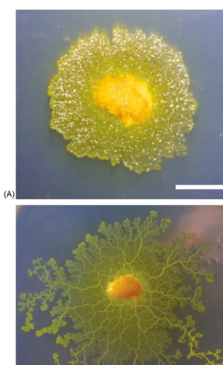
The amoeboid plasmodium of the slime mold P.
polycephalum is a large multi-nuclear single-cellular
organism (Fig. 1A). In a fully developed plasmodium
flat sheet-like areas at the edge are connected by more
centrally located tubular structures as visible inFig. 1B.
Being a single cell, the plasmodium – which can extend to over 20 m in diameter – does not possess a nervous system. It relies on intracellular information processing to integrate local sensory information and to generate an appropriate response to stimuli. Different areas within the plasmodium communicate by protoplasmic flow. This oscillatory flow of protoplasma is called shuttle streaming and provides a transport mechanism for nutrition and signals. A dynamically reconfiguring network of tubes, formed from gelled cytosol, directs the flow of protoplasma as well as the overall movement and growth direction of the cell. It has been observed that the rhythm of shuttle streaming is synchronised with intracellular oscillatory behaviours such as oscillations
in ATP concentration, Ca2+ concentration, and the
plasmagel/plasmasol exchange rhythm (Ueda et al.,
1986). This oscillatory rhythm is known to increase in frequency in the presence of attractive stimuli (glucose, warmth) and, conversely, slows down if a repulsive
Fig. 1. Plasmodium ofPhysarum polycephalum. The early stage (A) and in developed form, approximately 8 h later (B). In both panels the length of the white bar corresponds to 10 mm.
Ridgway, 1976). The plasmodium is often viewed as a system of coupled oscillators and the oscillations are implicated in the information processing mechanisms of the Physarumplasmodium. The oscillatory behaviour has been studied from the dynamical systems perspec-tive. A collective oscillator model with a limit cycle was
introduced by Takamatsu et al. (1997). Recently,Tero
et al. (in press) suggested a reaction-diffusion model for cell fusion between two plasmodia that exhibits an anti-phase oscillation characteristic.
The plasmodium can be regarded as an autonomous distributed system. In a series of studies Nakagaki and coworkers found that this natural parallel processor can solve small instances of optimisation problems and find
an optimal path through a maze(Nakagaki et al., 2000,
2001). In the context of the present work the pattern-ing of the plasmodium with masks is particularly
rele-vant (Takamatsu et al., 2000a,b). Our architecture for a Physarum robot controller draws on this technique for constructing coupled nonlinear oscillator circuits
(Takamatsu and Fujii, 2002).
3. Cellular robot control
The objective here is to make the microphysical scale of cellular information processing amenable to robotic control applications. To achieve this aim, we require a system in which signals from the environment are trans-duced to a cell and processed using the micro physical features of intracellular information processing. Then, the results of the cellular computation need to be ampli-fied to steer the robot. After these two components of the cell–robot interface have been established, the intracel-lular level information processing can engage with the macroscopic environment of the robot in an interaction
loop across physical scales (Fig. 2).
Conrad (1996)emphasised the importance of the mi-crophysical scale for the problem solving behaviour of biological systems. He introduced the conceptual picture of a vertical percolation of signals through a hierarchy of physical structures. The underlying assumption of this concept is that evolution recruited the dynamics on all levels of scale for the efficient information processing required in autonomous systems capable of negotiating a complex hostile environment in real-time. To instanti-ate such a device and to provide a testbed for exploring and evaluating of bio-mimetic principles of cross-scale information processing in artificial devices, we have im-plemented a robot and the requisite cell–robot interface.
3.1. A pole-free legged robot
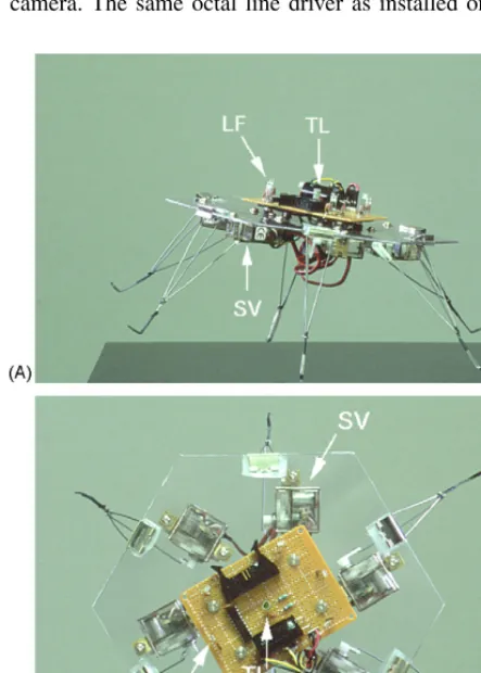
An omnidirectional walker design was adopted for the robot because it enables us to utilise the oscillatory be-haviour of the cell more directly for driving locomotion and allows us to more readily understand the dynamics of the robot. The six-legged configuration with a
hexag-onal body shape is pictured in Fig. 3. The hexagonal
platform is equipped with sensors equally in all six di-rections, resulting in a pole-free robot that can move and sense omnidirectional.
The chassis of the robot is a 2 mm thick sheet of acrylic plastic in the shape of a hexagon with 115 mm edge length. A circuit board mounted on the top of
the chassis (visible inFig. 3B) carries six light to
Fig. 2. Cell–robot–environment interaction loop.
board also carries a connector for a tether which sup-plies 5 V for the sensor circuitry (six TSL237 and one 74ACT240), separate 5 V for the leg actuators, 12 V for an RS232 serial interface, the RS232 signal, and the buffered signal lines of the six light sensors. Fur-thermore, two LEDs of different colour are mounted on the top circuit board to facilitate tracking of po-sition and orientation of the robot with an overhead camera. The same octal line driver as installed on the
Fig. 3. Six-legged robotic platform, side view (A) and top view (B). The hexagonal body carries six light-to-frequency converters (LF) and six legs driven by servos (SV). To assist in tracking the 2D-movements of the robot, two LEDs are used as tracking lights (TL).
robot (74ACT240) is used at the other end of the tether to receive the frequency-coded sensor readings and is connected through six adjustable voltage di-viders to six input channels of a sound card (Sound Blaster Live-Value, Creative Technology Ltd.,
Singa-pore;http://www.creative.com) in a personal computer
(PC). Six pulse-width controlled mini servos (PARK HPX, Grand Wing Servo-Tech Co. Ltd., Taipei, Taiwan;
http://www.gws.com.tw) of the type used in radio con-trolled air planes are mounted to the underside of the acrylic chassis. Each servo provides a nominal torque of 4.2 kg/cm at 4.8 V and drives an approximately 100 mm long triangular leg formed from 1 mm diameter steel wire. The pulse trains for the six servos are generated on-board with a peripheral interface controller (Mini SSC II, Scott Edwards Electronics Inc., Sierra Vista, AZ, USA;
http://www.seetron.com) which is mounted centrally on the underside of the chassis and receives its commands through a serial port of the PC. A leg is mounted in centre
of every edge of the hexagonal chassis (cf.Fig. 3B) with
the spring of a 20 mm foldback paper clip and is driven perpendicular to the chassis’ edge by a lever (1 mm steal wire) connected to the servo actuator. This simple design offers excellent static stability and allows for numerous possible gait patterns with only one degree of freedom for each leg.
3.2. Physarum circuits
3.2.1. Materials and methods
The plasmodia used for the experiments are cultured in the dark on wet paper towel (Crecia Co.,Ltd., Tokyo, Japan,
http://www.crecia.co.jp) in a plastic box at room tempera-ture. Oatmeal is fed once or twice a day. All experiments have been conducted on a 1.5% agar gel plate (polystyrene 90 mm×15 mm Petri dish, Ina Optica Co. Ltd.) with the plasmodium kept in food hunger for at least 6 h. As noted above, the plasmodium prefers not to migrate from a moist surface to a dry region. For the dry masking of the agar gel, we chose plastic film (WT-OHP100, Seikyo, Kobe, Japan;
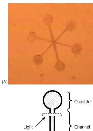
[image:4.586.40.262.328.638.2]pat-Fig. 4.Physarumoscillator circuit. The plasmodium is patterned as six oscillators with star coupling (A). The picture shows the view provided by the CCD camera indicated in Fig.5. A diagrammatic view of one branch is shown on the right (B). The oscillator nodes have a diameter of 3 mm; channels are 6 mm×0.5 mm. A dashed box delineates the area irradiated for light stimulus.
terned to any desired shape with a sharp blade. In the experi-ment, the Petri dish with the plasmodium was placed on a fiber optic back light (1P100-1000F-1G8-MPM-R, OPTEL, Tokyo, Japan;http://www.optel.co.jp) and illuminated with a halogen light source (OHX-100A, OPTEL) filtered with a 600 nm inter-ference band pass (NT46-152, Edmund Optics Japan Co. Ltd.,
Tokyo, Japan; http://www.edmundoptics.com). Physarumis not affected by light near this wavelength(Renzel et al., 2000). Light transmitted through the plasmodium was detected with a CCD camera (HOGA, Kyoto, Japan) and recorded typically at 2 s intervals by a PC through an image capture board (GV-VCP2/PCI, I-O Data,http://www.iodata.jp). All experiments were conducted in the dark at 20◦C.
3.2.2. Architecture of Physarum circuits
In the experiments reported here, we used the star
shaped circuit shown inFig. 4A. It consists of six
circu-lar wells of 3 mm diameter each, coupled at the centre through six channels. With this geometry, the part of the plasmodium contained within a well will be synchro-nised and can be assumed to form a single oscillator
(Takamatsu and Fujii, 2002). It is also known that adja-cent plasmodia fuse into a single one and that, under the conditions considered here, plasmodia will never split up. This fact is used to grow the plasmodium into the
mask. A tip portion (≈3 mm×3 mm) cut from cultured
larger plasmodium is placed on the side of each well as a seed. The mask thus prepared is incubated in the dark for at least 4 h. The plasmodia migrate from the seeds onto the exposed agar surface and fuse at the centre where the channels meet. After the plasmodia fused into a single cell, incubation is continued for an additional 3 h. After total of 7 h incubation, tube structures are established in the channels. The circuit obtained corresponds to six in-dividual nonlinear oscillators mutually coupled through the tubes formed in the circuit channels.
3.3. The cell–robot interface
Having implemented the above, it is necessary to
combine the Physarumcircuit with the robot. The
[image:5.586.52.244.62.332.2]ar-chitecture illustrated inFig. 5is based on an all-optical
[image:5.586.95.449.508.637.2]interface between cell and robot. It makes use of three phenomena. First, plasmodia are repelled by white light
(Ueda et al., 1988). Second, the light transmission of plasmodia is inversely proportional to their thickness
(Nakagaki et al., 1999). And, third, as previously stated, the plasmodium is insensitive to light near 600 nm
(Renzel et al., 2000).
Signals from the robot’s six light sensors are trans-duced to the plasmodium by shining a band of white light
on the coupling channel of an oscillator (cf.Fig. 4). To
this end, we project one mask from a set of dark masks
with suitably positioned white lines onto thePhysarum
circuit. We use a video projector with standard optics and a light path of 1.2 m. By this way only a fraction of the projectors image covers the circuit, but the obtained resolution is sufficient to send signals to specific chan-nels. Our observations suggest that light stimulation of an oscillator’s channel weakens the coupling of this oscillator to other oscillators in the circuit. Such a weakening can alter the behaviour of the oscillator system.
To read out the response of the plasmodium, the cir-cuit is illuminated through its agar base by orange light. The intensity of the transmitted light is recorded by a
CCD camera. The image of the camera (shown inFig.
4A) provides state information for all six oscillators
pat-terned in the plasmodium. To calculate the amplitude of
an oscillator, the average brightness of a 5×5-pixel area
centred over the well of the oscillator under considera-tion in the camera image is taken. For analysis purpose, we eliminate camera noise by calculating moving tem-poral averages with a window size of 30 s.
It is now possible to transmit signals from the robot’s light sensor to the plasmodium cell and to read the cell’s oscillations in the six wells of the circuit, which is then used to control the robot’s leg actuators. The oscillations of the plasmodium typically have a period in the order of 1–2 min. Practically, therefore, it is convenient to up-convert the oscillator frequencies rather than to use them directly for driving the actuators.
By using the arrangement above described, the closed loop interaction between the plasmodium cell and the
robot’s environment depicted inFig. 2 is established.
Each plasmodial oscillator controls the rhythm of one robot leg. In combination, the leg oscillations lead to a locomotion of the robot. As a consequence of the robots motion, the light levels sensed by the robot changes. The change is communicated back to the plasmodium that responds with alternations in its oscillatory behaviour.
4. Behaviour of aPhysarumcircuit
Two properties of thePhysarumcircuit are essential
to make the conceived architecture practical. The cou-pled oscillatory system has to yield oscillation patterns that lead to a robot gait. And, equally important, the gait
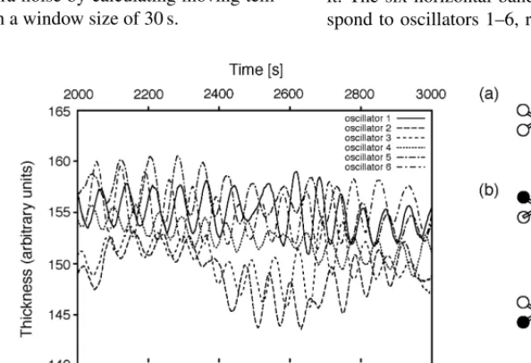
pattern has to be responsive to stimuli.Fig. 6shows
typ-ical oscillatory behaviour of the wells in thePhysarum
[image:6.586.126.423.462.665.2]circuit. The upper graph shows the relative thickness, i.e., the amplitude, measured for the six oscillator wells. The lower graph shows the binarized phase for the six oscillators on the same time axis as the graph above it. The six horizontal bands from top to bottom corre-spond to oscillators 1–6, respectively. A black vertical
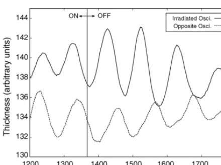
Fig. 7. Effect of light stimulus on oscillation of the plasmodium; sam-ple selected from a long time series. The amplitude of an oscillator that receives a light stimulus is drawn as solid line, the amplitude of the oscillator opposite to it as dashed line. Irradiation is on untilt=1370 s (vertical line) and off thereafter. As soon as the light stimulus is re-moved, the oscillation switches rapidly from in-phase to anti-phase.
line for an oscillator indicates that at this point in time its thickness was increasing. Note that the oscillation pat-tern changes spontaneously, even without light stimulus, from a rotational pattern (a) to an alternating pattern (b). The position of oscillator labels used in the legend of the amplitude curves (upper graph) is shown in (c).
The anti-phase oscillation phenomenon supports robot locomotion. As will be described in the following section, an anti-phase oscillation gives rise to an effec-tive gait pattern. The experimental results obtained so far show that the six-oscillator circuit exhibits in-phase or anti-phase pattern under many circumstances. If we can modulate the relative phases of a pair of oscillators by light stimuli and manage to avoid interfering, un-favourable oscillations, the robot can be made to walk in any desired direction under the control of the plasmod-ium cell.
Unexpectedly, we found that irradiating the channel of an oscillator has little effect on its rhythm. However, if a channel is stimulated with light and the stimulus is removed, the stimulated oscillator and the oscillator located directly opposite to it rapidly go into anti-phase
oscillations as shown inFig. 7. A possible explanation of
this phenomenon may be found in the fact that the driving force of protoplasmic flow is proportional to phase
dif-ference between two areas of the plasmodium(Nakagaki
and Ueda, 1996). The switch to anti-phase oscillation upon removal of the light stimulus may be due to an autonomous recovering process. As shown by these ex-periments, the six-oscillator star circuit design fulfils the two basic requirements for the cellular robot control ar-chitecture.
5. Robot locomotion with coupled oscillators
To investigate the possible gait patterns that can be generated by coupled oscillator circuits and how the gait can be modulated we conducted a set of experi-ments in which the actuators of the robot are driven by a coupled nonlinear oscillator system implemented in software.
Each of the six legs of the robot is driven directly with the amplitude of one of six van der Pol oscillators. The choice of van der Pol oscillators was motivated by the
works ofTakahashi et al. (1997)andNomura (2001)on
simulation of plasmodium behaviour. The fully (all-to-all) connected oscillators are described by
dxi(t)
dt =yi(t), dyi(t)
dt =ε(1−2βixi(t)−xi(t)
2
)yi−xi(t)
+ 6
j=1
κij(xj(t)−xi(t))
+ 6
j=1
σij(yj(t)−yi(t)) (1)
wherexi, xj correspond to the six van der Pol
oscilla-tors,ε, βrepresent the nonlinearity, andκij,σij are the coupling constants among the oscillators. In addition, to account for the variability seen in the living
oscilla-tors, κij andσij are slightly varied at every time step
with κt+ij 1=κtij+κij and σijt+1=σijt +σij, where
κij, σij are Gaussians with zero mean and unit
vari-ance. Consequently, as is the case in the Plasmodium
circuit, the network of oscillators dynamically changes and is never trapped in a stable or periodic state.
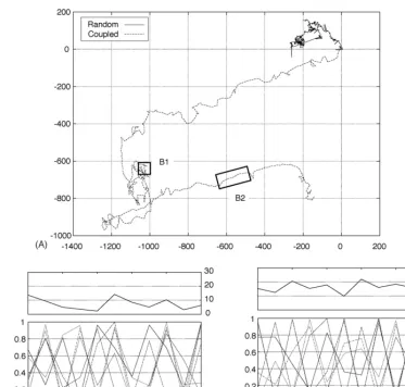
A typical trajectory of the robot under control of the
van der Pol oscillator system is depicted in Fig. 8A.
Control experiments conducted with in-phase periodic movements of the legs (not shown) and random
move-ments of the legs (solid line inFig. 8A) confirmed that
the direction of locomotion of the robot is not biased by unintentional asymmetries arising from variations in the construction of the robot.
In the experiment shown the parameters are restricted to the range of: ∈[0,3], κ∈[0,0.15], σ∈[0,0.2]
and, for simplicity,β=0. Under these conditions, we
observe both wiggle (Fig. 8B1) and walking. Directed
Fig. 8. Trajectories of robot migration. The trajectories for randomly driven legs (solid line) and legs driven by coupled oscillators (dashed line) are compared for the same number (579) of steps (A). The distance from the start position of the robot is shown on thex- andy-axis in cm. Panels B1 and B2 show the migration distance in mm for each time step (top) and the phases of the legs (bottom). The two panels correspond to the movement indicated by the labelled boxes in (A).
with each other yield an efficient gait with a stepping
movement (Fig. 8B2).
6. Conclusions and outlook
We have presented an architecture for a cell-based
robot controller and have shown that cells ofP.
poly-cephalumcan provide the functionality required by our
design. Previous reports onPhysarumbased oscillator
systems used a fixed coupling strength determined by the width of the channel connecting oscillators. Our ex-periments show that light signals can be used to dynami-cally alter the coupling among oscillators and thus point to a path for interfacing the sensors of the robot with the plasmodium. Clearly, this work is at an early stage and further studies are needed to explore the properties, capabilities and limitations of such a system.
We believe that the use of biological cells for the con-trol of autonomous robots is attractive because of several features difficult to obtain with other technologies. The nano-architecture of the robot controller self-reproduces and is therefore of low cost. Power requirements are exceedingly low; circuits of the type employed here can operate for several days without supply. The controller can be stored for a long time in a dry dormant state and activated by moisture. Moreover, the nano-architecture of the controller comes with a build in self-repair capability. In the foreseeable future, it may be possible to use the tools of synthetic biology to customise cell-based robot controllers for a particular application
Acknowledgments
The authors thank Masashi Aono for discussions and technical advise. The work reported here was supported in part by the Science and Technology Agency of Japan through the Center of Excellence (COE) program. ST would like to thank the Hara Research Foundation for travel support.
References
Adamatzky, A., de Lacy Costello, B., Melluish, C., Ratcliffe, N., 2004. Experimental implementation of mobile robot taxis with onboard Belousov-Zhabotinsky chemical medium. Mater. Sci. Eng. C 24 (4), 541–548.
Blake, W.J., Isaacs, F.J., 2004. Synthetic biology evolves. Trends Biotechnol. 22 (7), 321–324.
Brooks, R., 1990. Elephants don’t play chess. Robot. Auton. Syst. 6 (1–2), 3–16.
Brooks, R., 1991. Intelligence without representations. Artif. Intel. 47, 139–160.
Cariani, P., 1992. Some epistemological implications of devices which construct their own sensors and effectors. In: Varela, F.J., Bourgine, P. (Eds.), Toward a Practice of Autonomous Systems: Proceedings of the First European Conference on Artificial Life. MIT Press, Cambridge, MA, pp. 484–493.
Conrad, M., 1972. Information processing in molecular systems. Curr. Mod. Biol. (now BioSystems) 5, 1–14.
Conrad, M., 1989. The brain-machine disanalogy. BioSystems 22, 197–213.
Conrad, M., 1995. Scaling of efficiency in programmable and non-programmable systems. BioSystems 35, 161–166.
Conrad, M., 1996. Cross-scale information processing in evolution, development and intelligence. BioSystems 38, 97–109.
Conrad, M., 1999. Molecular and evolutionary computation: the tug of war between context freedom and context sensitivity. BioSystems 52, 99–110.
Durham, A.C.H., Ridgway, E.B., 1976. Control of chemotaxis in Physarum polycephalum. J. Cell Biol. 69, 218–223.
Fujita, M., Kuroki, Y., Ishida, T., Doi, T., 2003. A small humanoid robot sdr-4x for entertainment applications. Proceedings of Interna-tional Conference on Advanced Intelligent Mechatronics, pp. 435– 442.
Liberman, E.A., 1979. Analog–digital molecular cell computer. BioSystems 11, 111–124.
McCarthy, J., Hayes, P., 1969. Some philosophical problems from the standpoint of artificial intelligence. Mach. Intell. 4, 463–502. Nakagaki, T., Ueda, T., 1996. Phase switching of rhythmic
con-traction in relation to regulation of amoeboid behavior by the plasmodium ofPhysarum polycephalum. J. Theor. Biol. 179, 261– 267.
Nakagaki, T., Yamada, H., Toth, A., 2000. Intelligence: maze-solving by an amoeboid organism. Nature 407, 470.
Nakagaki, T., Yamada, H., Toth, A., 2001. Path finding by tube mor-phogenesis in an amoeboid organism. Biophys. Chem. 92, 47–52. Nakagaki, T., Yamada, H., Ueda, T., 1999. Modulation of cellular rhythm and photoavoidance by oscillatory irradiation in the Physarumplasmodium. Biophys. Chem. 82, 23–28.
Nomura, S., 2001. Symbolization of an object and its freedom in biological systems. Ph.D. Thesis. Kobe University.
Rambidi, N.G., 2005. Biologically inspired information processing technologies: reaction-diffusion paradigm. Int. J. Unconvent. Comput. 1 (2), 101–121.
Renzel, S., Esselborn, S., Sauer, H.W., Hildebrandt, A., 2000. Cal-cium and malate are sporulation-promoting factors ofPhysarum polycephalum. J. Bacteriol. 182 (24), 6900–6905.
Simpson, M.L., 2004. Rewiring the cell: synthetic biology moves towards higher functional complexity. Trends Biotechnol. 22 (11), 555–557.
Takahashi, K., Uchida, G., Hu, Z., Tsuchiya, Y., 1997. Entrainment of the self-sustained oscillation in aPhysarum polycephalumstrand as a one-dimensionally coupled oscillator system. J. Theor. Biol. 184, 105–110.
Takamatsu, A., Fujii, T., 2002. Construction of a living coupled oscillator system of plasmodial slime mold by a microfabricated structure. Sens. Update 10 (1), 33–46.
Takamatsu, A., Fujii, T., Endo, I., 2000a. Control of interaction strength in a network of the true slime mold by a microfabricated structure. BioSystems 55, 33–38.
Takamatsu, A., Fujii, T., Yokota, H., Hosokawa, K., Higuchi, T., Endo, I., 2000b. Controlling the geometry and the coupling strength of the oscillator system in plasmodium ofPhysarum polycephalum by microfabricated structure. Protoplasma 210, 164–171. Takamatsu, A., Takahashi, K., Nagao, M., Tsuchiya, Y., 1997.
Frequency coupling model for dynamics of responses to stimuli in plasmodium ofPhysarum polycephalum. J. Phys. Soc. Jpn. 66, 1638–1646.
Tani, J., Ito, M., Sugita, Y., 2004. Self-organization of distributedly represented multiple behavior schemata in a mirror system. Neural Networks 17 (8–9), 1273–1289.
Tani, J., Nolfi, S., 1999. Learning to perceive the world as articulated: an approach for hierarchical learning in sensory-motor systems. Neural Networks 12, 1131–1141.
Tero, A., Kobayashi, R., Nakagaki, T., in press. Coupled-oscillator model with a conservation law in rhythmic amoeboid movements of plasmodial slime mould. Physica D.
Ueda, T., Matsumoto, K., Kobatake, Y., 1986. Spatial and temporal organization of intracellular adenine nucleotides and cyclic nu-cleotides in relation to rhythmic motility in physarum plasmodium. Exp. Cell Res. 162 (2), 486–494.
Ueda, T., Mori, Y., Nakagaki, T., Kobatake, Y., 1988. Action spectra for superoxide generation and UV and visible light photoavoidance in plasmodia ofPhysarum polycephalum. Photochem. Photobiol. 48, 705–709.