Data validation in 3D cadastre
Sudarshan Karki13, Rod Thompson12, Kevin McDougall3
1Department of Environment and Resource Management, Queensland,
Australia, 2TU Delft, the Netherlands, 3University of Southern Queensland, Australia
Abstract
1. Introduction
The cadastre deals with land and the rights associated to it. It can be consi-dered to be a combination of geometrical and attribute data which is regu-lated and governed by the country‟s constitution and other laws for defined purposes. The technical and judicial framework assist in defining the cada-stral framework along with other drivers like the land market and present land administration needs. In recent years there has been an increasing trend towards the unbundling of property rights and a demand for more ef-ficient usage of our traditional 2D cadastre through 3D developments. Accommodating and assisting the growth of 3D cadastre as an integral part of the land administration is being largely driven by technology. In many countries, the judicial framework supports a 3D cadastre, while in some others it is yet to be developed. The technical aspects of storing, retrieving, manipulating 3D cadastre is yet to be developed at par with 2D cadastre. Much of the problem lies in defining a data model for 3D cadastre, the in-teractions with the existing database and data capture methods, and the range of possible shapes and combinations of 3D objects in existence at present and those likely to be in the future. Additionally, support for the subdivision or consolidation of these 3D objects, validation rules for checking the data before, during and after entry into the system, and the optimal validation rules for entry of the data to the system must be consi-dered.
This paper explores the similarities and dissimilarities in the 2D and 3D cadastral data context, focuses on differences between validation of a sin-gle object and validation of a set of neighboring objects or partitions of space in the 3D cadastral context, and then narrows down to the optimal validation rules necessary for a 3D cadastre keeping in mind that mixed representations of both 2D and 3D can co-exist in the same dataset or ju-risdiction.
1.1 Structure of the paper:
This paper is structured in six main sections: Introduction, Representations based on existing methods, Validation extended from 2D to 3D, Validation in 3D cadastral context, Representations based on ISO19152 LADM, Dis-cussions and further research.
applicabili-Section 3 is a short discussion on validation extending from 2D to the 3D domain. Questions such as what is validation? why do we validate? and when do we validate are discussed briefly to emphasize the need for a va-lidation.
Section 4 of the paper focuses on a 3D cadastral validation situation based on the internal geometry of a 3D parcel, the relationships of 3D par-cels to the base parcel, relationships to other parpar-cels, unique geometrical situations that might exist, effects of further processing of 3D geometry and certain entry level validations.
Section 5 deals with the geometrical structures and validation require-ments of the newly developed ISO19152 Land Administration Domain Model (LADM).
Section 6 concludes the paper with a Discussion summarizing the paper, with a sub-section on Further Research which proposes work that needs to be extended and studied in depth.
2 Representation of a 3D parcel based on existing methods
Although significant work has been done e.g. (Kazar et al) on the valida-tion of generic 3D geospatial objects, cadastral 3D parcels have validavalida-tion requirements which are more restrictive in some regards (e.g. some 3D parcels may be required to be within base 2D parcels), but may be less re-strictive in other regards.
This section deals with the various existing ways of constructing 3D ob-jects, and the validation requirements for them. While the rest of the paper focuses on boundary representations to define a parcel or 3D object, this section discusses other ways of constructing 3D objects, which may pro-vide jurisdictions with options to progress to a 3D cadastre based on their individual circumstances like legal requirements, existing data structure and proposed usage etc.
2.1 Objects constructed using tetrahedrons
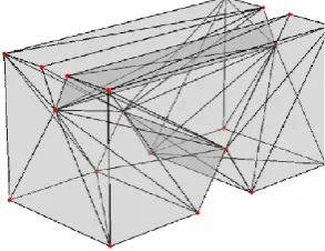
The tetrahedron method of generating 3D objects (see Fig 1), has been employed in 3D GIS and extensively studied by Penninga et al (2006) and Rahman and Pilouk (2007). The same principles can be applied to create 3D cadastre using tetrahedrons.
Validation must ensure:
The nature of the decomposition ensures that the object is unambiguously defined by a set of tetrahedrons, so the main objective is met, but there are several additional requirements. 3. Composite external faces that are intended to be planar should be
planar. (see discussions below)
[image:4.595.237.384.262.375.2]4. There must be no gaps between tetrahedrons within the objects (this is achieved via a topological representation; e.g referring to nodes via their id and not to repeat the coordinate values)
Fig. 1. A solid object created using tetrahedrons (Ledoux 2009)
Discussions:
The validation rules to be considered after Penninga et al (2006) and Rahman and Pilouk (2007) are:
where tetrahedrons are in contact, the contact may be at a single point only, along a line, or on a complete face. No partial contact should be allowed.
where an object has planar faces, but these are broken into triangles by the tetrahedronization process, checks must be done to determine whether the original planarity is lost due to rounding errors of vertex coordinates.
it may be considered important that a relationship is maintained between the faces to ensure that they can be kept coplanar (for example, the nearest faces of Fig. 1 clearly should be planar, but there is no indication to validate this).
where vertices meet, the coordinates must be the same.
2.2 Objects constructed from simpler solids
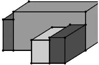
[image:5.595.222.390.223.334.2]The composite solid method of generating a 3D block (see Fig 2), can be employed for very low level representations of a 3D object or a 3D city model resembling LoD1 in CityGML (Kolbe 2009). A similar approach can be used to define 3D cadastral parcels.
Fig. 2. Solids made from simpler solids (Ledoux 2009)
The simple solids produced would have the advantage of very simple validation constraints as well as quick answers to area and volume queries. It would also be easier to represent in a variable limiting height situation. Complex shapes can be generating by addition of simple volumes or sub-traction to eat away from objects.
Where composite shaped volumes are built by eating away surfaces, making sure of the coplanarity. Gaps and intersections may be left during volumes addition or subtraction as well as in contiguous parcels, so that would have to be checked.
2.3 Regular Polytope
Fig. 2.1. Example of a regular polytope
2.4 Objects constructed by extruding
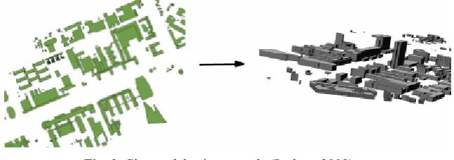
Three dimensional “objects” can be created using extrusion in many soft-ware. This is a convenient way to visualize 3D where variables such as in-dividual object heights, constant heights for objects of same elevations and sometimes even the elevations of the land can be included to generate the 3D view. This may sometimes be the way to generate 3D cadastral views in non-complex situations, where no analytical facilities are required.
Fig. 3. City model using extrude (Ledoux 2009)
[image:6.595.143.467.436.550.2]demon-strated by Ledoux (2009). Also, it is more difficult to integrate 3D vo-lumes with 3D terrain.
3. Validation, extended from 2D to 3D
The object of validation in a 2D/3D cadastral environment is to form a ri-gorous definition of what is a valid object. This has to be considered in 2D and 3D as well as a mixed representation of both in the cadastre. In the ca-dastre as well as in other applications, validation needs to be done at vari-ous stages of data entry and processing to ensure the integrity of the data and also that future analysis or operations are performed within their in-tended bounds.
Within the context of validation we need to answer the following: What is validation? (Concepts, approaches).
Why we are validating? (Needs analysis, purpose of validation). How we are validating? (Validation rules).
When should we validate? (At data capture, data entry, post processing etc).
Validation is the process of checking for possible errors in data via pre-defined rules usually before the data is processed or entered into the sys-tem. Validation takes on different meanings depending upon the context and circumstances of the application. Validation, for example, to a data-base administrator would be quite different to that for a web page develop-er. While the former‟s validation strategies would be focused on defining integrity checks and business rules, the latter would probably be more con-cerned about developing strategies to accept or reject entries that users make over the internet and may possibly be malicious. There are lots of common premises for validation as well, for example, data security, logical consistency, data within pre-defined range, format of data, checks for null values etc.
informa-tion sometimes becomes complex with crossing networks, multiple strata etc.
Although there are similarities as well as dissimilarities in the approach-es of the various validation requirements and strategiapproach-es, the principlapproach-es gen-erally remain consistent. Gengen-erally, an attempt is made to identify all known issues then validation rules are defined against which data are checked before any further processing is undertaken.
This holds true in the 3D cadastral context as well. At this stage it is as-sumed that there is a 2D cadastre in place, which supports the key ele-ments of storing and retrieving geometrical and attributes data in the sys-tem. Thus, storing of attribute information for a 3D parcel can be expected to raise few extra changes. It is the geometrical aspect that is highly com-plicated to store and validate before any manipulations can be performed.
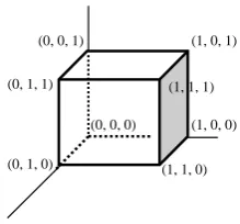
Geometrical aspects are complicated in the 3D cadastral context because of the variety of shapes and geometries that are possible in a volumetric space. At present there is a general lack of consensus on how best to store or depict the data among the major software dealing with 3D data. For ex-ample, using the Oracle database one can define nodes with x, y, z coordi-nates and use them to construct edges, faces and solid objects.
As in the example in Fig 4, it would be possible to define a polygon from four coordinated points or nodes, and then a solid using the six poly-gon faces. However, for a truly vertical face, the vertical coordinates would be treated as duplicate points in some software‟s validation rules, which can disallow entry of the data into the database, thus creating inte-roperability issues.
(0, 0, 0) (1, 0, 0)
(0, 1, 0)
(0, 0, 1) (1, 0, 1)
(1, 1, 0)
[image:8.595.245.355.473.575.2](0, 1, 1) (1, 1, 1)
Fig. 4. Defining a volume by enclosing faces
Of particular interest in the field of cadastral data is the emerging stan-dard ISO19152, the Land Administration Domain Model (LADM). This is an attempt to create an extensible standard that can be used to exchange cadastral information, and that can assist with the implementation of cada-stral databases. (Lemmen et al 2009).
As an example of validation, ESRI‟s specification of ParcelFea-tures_Topology (ESRI 2004) shows quite a comprehensive set of rules, to-lerances, participating feature classes and the feature to be checked against. Other software have similar rigorous checking in the 2D GIS do-main. This kind of checking is as yet to materialise in the 3D cadastre field because there is no agreed standard of validation of the 3D parcel and the ways of defining the rules are justified by the particular situation of the parcel itself (section 4).
Validation can be carried out in various stages during the life of the da-ta. In the 2D or 3D cadastral context, validation can start from the time a surveyor sets foot on the site to the time it is entered to the system and might continue throughout the transaction life of a parcel. Validation strat-egies depend on the various stages the data goes through, and also in the case of a 3D cadastre the various methods or options of storing the data. In the following section, various options, methods and issues associated with a 3D cadastre are dealt with in further detail.
4. Validation in 3D cadastral context
In this section, situations involving 3D geometry in the cadastral context are listed. These are followed by discussions on the minimum validations rules or specifications that would be required to address these circums-tances. In most cases, the 3D volume parcels are within the 2D base parcel, but exceptions may arise in the case of network objects when the 3D net-work object may extend beyond the base parcel.
The situations described below are classified into various groups based on similarity of conditions. They are based on:
1. Internal validity of 3D parcels. 2. Surface or base parcel.
4.1 Internal validity of 3D parcels
In the same way as it is necessary to ensure that 2D “polygons” have a va-lid definition, such as the simple feature specification by the Open Geospa-tial Consortium (OGC 1999), validity checks are necessary to ensure that representations of 3D regions are internally consistent. For example, in a boundary representation, the boundary must be complete, (watertight). Other issues like dealing with coplanarity, internal rings, constructing ver-tices, etc are equally important. These issues are explored in Kazar et al. (2008), to test for Closedness and Connectedness in particular.
4.2 Relationship to surface or base parcel
Unless the entire cadastre is to be represented in 3D, a mixture of 2D and 3D parcels will exist, with the vast majority being 2D. It is the nature of cadastral data that an identifiable set of parcels forms a base layer, which represents the primary interest in the land. In the following discussion, it is assumed that a set of base 2D parcels exists, and forms a non-overlapping partition of the area of the jurisdiction, and that appropriate validation and structural constraints are in place to ensure this. In many cases there will be secondary interests, like easements, represented by 2D parcels. These may form a second complete coverage but usually do not, and may be al-lowed to overlap.
In this section, the relationship between 3D parcels and the underlying base layer is explored, with reference to the validation tests that may be applicable.
Note that the term "base parcel" should not be taken to mean that it is physically below the "non-base" parcel(s). As noted by Stoter and van Oosterom (2006), the correct interpretation of what is known as a 2D par-cel is in fact a column of space from some (possibly unspecified) depth be-low the earth surface to some (possibly unspecified) height above. What is usually represented as the 2D parcel is the intersection of this column with the surface. However, it must be noted that both bounded and unbounded objects exist in 3D space, for example, objects with open top or bottom.
Requirements
The relationship between the base parcel and the 3D parcels creates validation requirements such as:
2. Checks on the upper and lower bounds of the 3D parcel (which may or may not have bounds on either ends).
3. Variable ground level in relation to the 3D bounds (where there are restrictions on the height above or below the surface to which rights or restrictions are imposed).
Discussions:
At least in Queensland, Australia, while the 3D parcels are initially created totally within the 2D parcels, (but this is not universal even in Queensland) this may not be preserved when the surface parcel is subdi-vided, e.g. a tunnel under a surface parcel does not prevent the owner of the surface parcel from subdividing it, as a result, requirement 1 above may not hold for all time.
The validation rules to make sure that the above conditions were met (if applicable) could include:
Ensure that the footprint of the 3D parcel is completely within the 2D parcel.
If the same horizontal stratum is considered, then it becomes a trivial 2D polygon check, however, as more 3D objects are compared to the base 2D parcel, the situation becomes increasingly complex as in the case of net-work objects.
Ensure that the extrusion above or below the surface by the 3D parcel was completely within the 2D parcel
If a building is considered to be built enveloping the total base parcel, then the mathematically vertical extrusion in given 3D reference system at right angles to the built surface might be different to the gravity vertical.
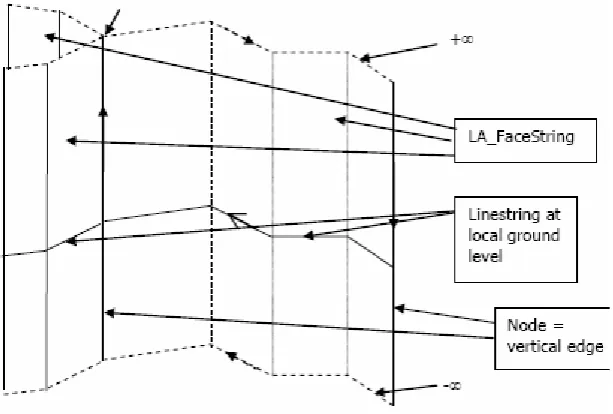
Ensure that the 3D parcel lies within the legal limits.
Fig. 5. Face string concepts of a 3D parcel based on 2D Line string at ground level ISO19152 (2009)
Ensure that there are no gaps or overlaps within the individual 3D units that are part of the 2D base parcel
Fig. 6. Complex shape formed when two network parcels cross below, and are ex-cised from a 2D parcel
4.3 Relationships to other parcels
Requirements
Beyond the relationship between 3D parcels and their enclosing base parcels, there is a need to consider the 3D parcels in relation to other par-cels, including:
1. Checks on situations where a 3D parcel meets 2D parcels.
2. Checks on the geometry and topology of the 3D parcel and its relationships with neighbouring 3D parcels.
Discussions:
Ensure that there are no gaps or overlaps among neighbouring 2D or 3D parcels.
what is in reality a 2D parcel to exactly abut a 3D parcel. Unless there is a complete partitioning of space in 3D, the question of gaps or overlaps is difficult to address. Reasonability checking can assist in locating such er-rors (e.g. finding very acute angles between adjoining surfaces). See sec-tion 5.5 for a discussion on topological encoding.
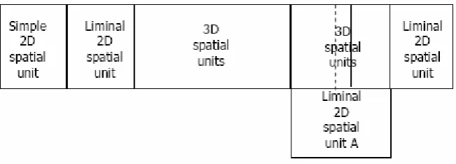
Fig. 7. Top view of mixed 2D and 3D representations ISO19152 (2009)
Ensure that the sum of the individual units of 3D floor area per strata was less than or equal to the base 2D parcel.
This is a trivial and obvious check to verify that the union of all 3D ob-jects per individual strata is totally within the base parcel, where 3D parcel are contained in identifiable strata, such as in a block of units.
Ensure that the faces between parcels are complete, so that distinct parcels are formed.
Parcels not separated by mismatching surfaces
Fig. 7.1. 3D representation of an incomplete subdivision
Ensure that self intersections or loops do not create new unintended parcels.
Again this is not difficult for a 2D parcel and these are already dealt with by most software; however, for a 3D parcel, it is more difficult to sure that there are no unintended slivers (or shells in 3D), as well as to en-sure that once this is resolved, the corrected surfaces remain coplanar (see Fig 7.2).
[image:15.595.198.419.441.637.2]Parcel created
by mismatching
edges
4.4 Unique geometrical situations
In this section, unique situations that involve utility networks, or different strata being owned by different parties, existing and officially allowed en-croachments or “hanging” parcels creating their own problems have been discussed.
Discussions:
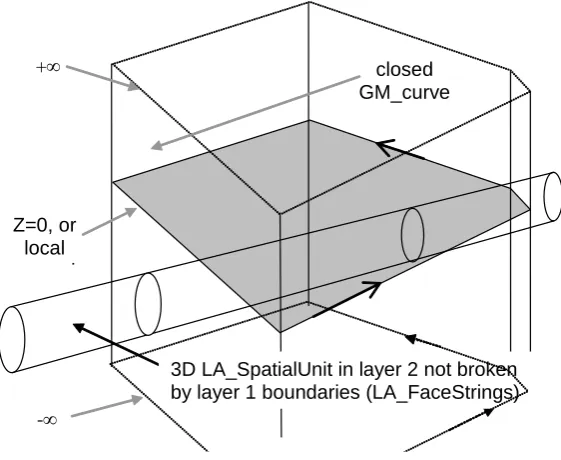
Utility Network. The main complexity of 3D network is its relationship to the base surface parcels (Fig 8). Several issues arise, like:
does the network subdivide when surface parcels are subdivided? recording the network when the surface parcel is not mapped in
cadastre (e.g. roads, rivers, reserves etc)
representing and recording the objects when the networks cross (e.g. tunnels and underground busways),
dealing with a situation when the network emerges to the surface, dealing with variable and irregular shapes and sizes etc.
Z=0, or local ground
+
-
closed GM_curve
[image:16.595.165.446.398.628.2]3D LA_SpatialUnit in layer 2 not broken by layer 1 boundaries (LA_FaceStrings)
Multiple strata. An ideal approach would be to allow multiple owners to rights and restrictions on multiple strata independent of each other, but since most cadastres are based on surface parcels, it becomes complex to maintain a relationship between them. This is highlighted in the case of network objects (see Fig 8) where they will need update operations such as extensions, excisions, splits and merges etc; but as a way around the complexity of maintaining the relationship between the surface and the network object, easements have sometimes been created as subsets of the surface parcels and amalgamated to match the network object. However, if multiple strata titles are allowed (see Figs 8 and 9), constraints must be considered in both the horizontal and vertical direction. In the horizontal direction, the network object would more often than not fall within many surface parcels, which would make it difficult to have a condition where the 3D object lies within the base parcel. In the vertical direction, objects such as crossing networks or tunnels would not encroach in 3D but would in 2D.
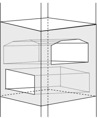
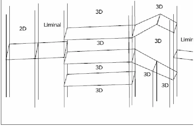
Fig. 9. Mixed use of face string and face to define both bounded and unbounded volumes (ISO 19152 2009). Liminal parcels are 2D parcels which directly adjoin
the faces of 3D parcels.
such a situation, the validation rules must be able to handle such exceptions as part of the validation process.
Fig. 11. (Left) 3D parcel number 10 of the Thai Rose, (Right) the restaurant over-hanging the footpath on the corner of Stanley Street and Main Street in Brisbane
Fig. 12. The Story Bridge over Brisbane River (Google Earth)
4.5 Further processing of the geometry
Requirements:
1. Effect of subdivision of the 2D base parcel on the 3D parcel and vice versa
2. Consolidation of contiguous or non-contiguous 3D parcels 3. Creating a total/partial reserve/easement on the 3D parcel
4. Limiting of vertical extent of certain 3D parcels by legislation (e.g. in mining areas, owner‟s rights to the land underground for a group of parcels may be more restricted in depth than other parcels in surrounding areas)
Discussions:
Effect of subdivision
there are two crossing networks below the subdivided parcel or above ground cables with legal space around them for protection, with each net-work behaving differently as far as subdivision is concerned.
Consolidation of 3D parcels
Consolidation would be the opposite of subdivision (where the rights, restrictions and responsibilities of two parcels are identical), similar con-straints would apply.
Creating easements
Creating an easement on a 2D base parcel would be similar to subdivi-sion, but if the easement was meant to match a 3D network object and the surface parcel amalgamated, then additional steps would be required to va-lidate the 2D-3D compliance
Vertical extents
Some areas of the same city, like Ipswich city near Brisbane, can have variable limits to the underground extent based on depth below surface to which owners can exercise their rights, so a reduced level of the ground surface needs to be recorded with the cadastre, so that checks can be made on the extent of the limiting depth.
Non Planar Surfaces
These greatly increase the complexity of the situation, particularly where curved surfaces intersect, which may result in 3D curved edges with no simple mathematical definition. For this reason, they are usually ap-proximated by a number of planar faces.
4.6 Entry Level Validations
In addition to the above mentioned situations, there may be other circums-tances involving geometry which needs to be mentioned for the sake of completeness.
Continuity of parcel.
enduring structure, which will permanently divide the parcels and which might even facilitate land transactions for the discrete lots. Both of the cas-es can be handled by cadastral software, but the choice depends on the predicted practical use of the subsequent data. Validation in such a situa-tion would be limited to a consistent logical approach rather than a rule based method, especially if there is an underground network through the parcel.
Reasonability.
Sometimes when entering data that has been collected in the field or com-piled from various sources into the system, due to operator level error, the identification number of two different plans may be incorrectly recorded as the same. This can only be distinguished from the case discussed above if the distance between the parcels exceeds a reasonable value.
Spatio-Temporal.
Although strictly not geometrical, the temporal aspects of cadastre need to be validated as more cadastres round the world are shifting towards a 4D cadastre. Most of the validation in the time dimension will be descriptive and subjective with the spatio-temporal validations being performed at event time itself and thus governed by any of the situations and rules above. In some problem domains it is preferable to treat this as four equiv-alent as 4D primitives, however, in the cadastral domain the simplifying assumption of changes as atomic events is usually acceptable.
5 Representations of a 3D cadastral parcel as allowed by the ISO 19152 LADM
The ISO19152 LADM, as it is being defined at present, has 5 ways of defining parcels (known in the standard as LA_SpatialUnit). These are:
1. point spatial unit (section 5.1) 2. text spatial unit (section 5.2) 3. line spatial unit (section 5.3) 4. polygon spatial unit (section 5.4) 5. topological spatial unit (section 5.5)
parcel, e.g. a parcel may be defined by lines on 3 sides but be completed by text.
All of these encodings are applicable in 2D or 3D, and different levels of validation are possible in each case. In general, these are in order of in-creasing sophistication, but also in order of inin-creasing validation require-ments as validation rules will differ for the geometrical/topological primi-tives and thus the features based on the primiprimi-tives.
Thus, it can be expected that point based spatial units may be applica-ble where little detailed knowledge of the cadastre is availaapplica-ble because of limited resources. While limited in its analytical functions, this encoding could be used to indicate the location of land parcels against a photograph-ic background.
Fig. 13. Classes LA_FaceString, LA_Face, LA_SourcePoint and LA_SpatialSourceDocument from the ISO 19152 LADM being developed
5.1 Point based encodings
LA_SpatialUnit
referencePoint: GM_Point
Fig. 14. Usage for Point based spatial units
5.2 Text based encodings
These spatial units are described textually, with the option of a reference point. While the description can be clear and unambiguous, very little for-mal validation is possible (see Fig 15). However, consistency in data col-lected and stored can be achieved by using standard forms during collec-tion and storage, such that gross or negligent errors can be immediately visible.
LA_SpatialUnit
referencePoint: GM_Point[0..1]
LA_FaceString
locationByText: PT_FreeText 1..*
[image:25.595.214.388.379.540.2]1..*
Fig. 15. Usage for Text based spatial units
5.3 Line based encodings
where data exists, in a basic and “un-processed” form, but being the best available, must be made available (see Fig 16).
LA_SpatialUnit
referencePoint: GM_Point[0..1]
LA_FaceString
geometry: GM_Curve
LA_Face
geometry: GM_Surface
1..2 1..2
[image:26.595.182.435.180.348.2]1..* 0..*
Fig. 16. Usage for Line based spatial units
5.4 Polygon based encodings
The polygon-based encoding stores 2D spatial units as simple polygons, while 3D spatial units are stored as polyhedra. Each FaceString represents one ring, and there should be at least one outer ring and zero or more inner rings. There is no intrinsic constraint that ensures that spatial units do not overlap, or that there are no gaps between them (see Fig 17).
LA_SpatialUnit
referencePoint: GM_Point[0..1]
LA_FaceString
geometry: GM_Curve
LA_Face
geometry: GM_Surface
1 1
1..* 0..*
[image:26.595.185.439.487.650.2]5.5 Topology based encodings
The topologically encoded form of spatial units is similar to the traditional topological encoding, and requires that each faceString, and each face is stored once only, with links to the left and the right spatial units (Figs. 16 and 18). As such, there is an in-built constraint that prevents certain kinds of invalid data from being represented, and is particularly suited to the situation where a complete non-overlapping partition of space is to be defined.
faceString left parcel
right parcel
[image:27.595.204.390.284.471.2]GM_Curve
Fig. 18. Topologically encoded 2D spatial units (with common faceString shaded) (ISO19152 2009)
Fig. 19. Reprint of Fig 9, showing topological encoding of the junction of 2D and 3D spatial units, side view of Fig 7 (ISO19152 2009)
6. Discussion and future work
The amount and completeness of the validation that needs to be applied to cadastral data varies according to the level of maturity and sophistication of the databases and applications involved. For that reason, ISO19152 de-fines alternative encoding strategies to ensure that for whatever level of va-lidation is achievable, the data can still be represented.
The decision as to what validation rules are to be applied by a particular registering authority will be made by that authority, and should be enabled by technology. This philosophy will ensure that authorities are not inhi-bited from developing a cadastral database by the high cost of ensuring pristine data.
As an example, a cadastre may begin life with a mixture of point and text based spatial units, gradually being upgraded to a line-based encoding. This form can be shown to be useful for certain applications, in spite of to-pological failings. Further effort could then result in a fully toto-pological ca-dastral database.
6.1. Further Research
This paper provides a preliminary investigation of the issues concerned with validation. It raises questions and identifies problems that need to be resolved to ensure a functional 3D cadastral system. As a generic study, in-depth analysis and investigations can be carried out on each aspect of the validation requirements during the stages of data collection, storage and processing. As specific requirements will differ, and not all of the issues raised in this paper are relevant to all 3D cadastres, user specific validation requirements need to be studied to suit individual circumstances.
7. Bibliography
ESRI, (2004) Parcels and the Cadastre Data Model Poster, Land Parcels Data Model, Accessed May 11, 2009 from
http://support.esri.com/index.cfm?fa=downloads.dataModels.gateway.
Friedrich J, (2004) Spatial Modeling in Natural Sciences and Engineering, Sprin-ger, Berlin, ISBN 3-540-20877-1.
ISO19107: ISO-TC211 (2001). Geographic Information - Spatial Schema. Gene-va, International Organization for Standards.
ISO 19152: ISO-TC211 (2009), Geographic Information, Land Administration Domain Model (LADM) Committee Draft Version 1, International Organiza-tion for StandardizaOrganiza-tion Technical Committee 211 distributed within ISO and CEN for voting 10 July 2009.
Kolbe TH (2009) Representing and Exchanging 3D City Models with CityGML. In: 3D Geo-Information Sciences. Lee J, Zlatanova S (Eds). Springer, Berlin.
Ledoux H, Meijers M (2009) Extruding building footprints to create topologically consistent 3D city models, In: Urban and Regional Data Management, UDMS Annual 2009, Krek A, Rumor M, Zlatanova S, Fendel E (Eds). CRC Press.
Lemmen C, Oosterom P, Uitermark H, Thompson R, Hespanha J (2009) Trans-forming the Land Administration Domain Model into an ISO standard (LADM as ISO 19152), FIG Working Week, Eilat, Israel.
OGC (1999) Open GIS Simple features Specification for SQL, Revision 1.1. Re-trieved Aug 10, 2009, from http://www.opengeospatial.org/standards/sfs.
OGC. (2004). "Geography Markup Language (GML)." GML-3.1.0.doc Retrieved Mar 2007, from http://www.opengeospatial.org/standards/gml.
Van Oosterom P, Zlatanova S (2008) Creating Spatial Information Infrastructures, CRC Press, Taylor and Francis Group, Boca Raton, USA, ISBN 978-1-4200-7068-2.
Penninga F, Van Oosterom P, Kazar BM (2006) A TEN-based DBMS Approach for 3D Topographic Data Modeling. Spatial Data Handling 06. 12th Interna-tional Symposium on Spatial Data Handling, Springer, http://www.rgi-otb.nl/3dtopo/documents/sdh06_TEN_dbms_v7_final3.pdf
Rahman AA, Pilouk M (2007) Spatial Data Modelling for 3D GIS, Springer, New York, ISBN 978-3-540-74166-4.
Stoter J (2004) 3D Cadastre. PhD thesis, Delft University of Technology, The Netherlands. http://www.ncg.knaw.nl/Publicaties/Geodesy/pdf/57Stoter.pdf
Stoter J, Oosterom P (2006) 3D Cadastre in an International Context, CRC Press, Taylor and Francis Group, Boca Raton, USA, ISBN 0-8493-3932-4.
Thompson RJ (2007) Towards a rigorous logic for spatial data representation, PhD thesis, Delft University of Technology, The Netherlands, http://www.rgi-otb.nl/3dtopo/documents/RGI-011-52.pdf