An Object Web-based Approach to Earthquake
Simulations
Geoffrey C. Fox(1), Ken Hurst(2), Andrea Donnellan(2), and Jay Parker(2)
(1) School for Computational Science and Information Technology and Department of Computer Science, Florida State University, Dirac Science Library, Tallahassee, Florida [email protected]. (2)Jet Propulsion Laboratory/California Institute of Technology, Pasadena California
Abstract
Computer simulations and sophisticated data processing will be key to substan-tial gains in understanding the earthquake process. Emerging information tech-nologies make possible a major change in the way computers are used and data is accessed. An outline of a realizable computational infrastructure includes standardization of data accessibility, harnessing high-performance computing algorithms, and packaging simulation elements as distributed objects across wide networks. These advances promise to reduce dramatically the frustration and cost of doing earthquake science as they transform the fragmentary nature of the field into one of integration and community
1: GEM Computational Infrastructure: GEMCI
We are designing a building a modern computational environment GEMCI to support different types of activities in the earthquake simulation field (Fox 2000[1]). It is built assuming large-scale parallel machines used to perform simulations and with powerful distributed networks to support scientists around the world collaborating on a given problem. The components of GEMCI can be divided into eight areas.
1) Overall Framework including agreement to use appropriate “commodity industry standards” such as XML (a language for metadata) and CORBA (a distributed object access standard and broker), as well as more specialized high performance computing standards like MPI (Message Passing Interface).
2) Use of GEMCI to construct multiple Problem Solving Environments (PSE’s) to address dif-ferent scenarios.
3) Web-based User Interface to each PSE. This would be designed so that one can access the information either from conventional PC/Workstation clients or from large displays (like CAVE’s or Powerwall’s) or perhaps more interestingly from wireless hand held devices.
4) Simulation engines built in terms of the GEMCI framework
5) Geophysical-specific libraries such as modules to estimate local physics and friction. These would also use the GEMCI framework, which would already include generic libraries
6) Data analysis and Visualization
7) Data Storage, indexing and access for experimental and computational information
8) Interactive Analysis and Rapid Prototyping Environment for developing new phenomenol-ogical models -- this includes visualization aspects and would be largely on the client (the local lightweight workstation). In contrast, the large simulations in 4) above, are naturally thought of as distributed server side computational objects.
standards and technologies. This describes the “coarse grain” (program level) structure of the GEMCI environment. There are myriad important details inside each module (or grain), which could be a finite element simulation code, data streaming from a sensor, a visualization subsys-tem, a Java eigensolver used on the client side or field data archived in a web-linked database. Here we summarize the nature of the resultant problem solving environments and in the final sec-tion, illustrate how these ideas can be integrated together into a variety of different scenarios. These essentially correspond to different problem solving environments that can be built by using the same GEMCI framework to link GEM components in various ways. We use the emerging internet software and standards infrastructure to build GEMCI. This corresponds to the merger of Internet (HTTP, HTML, XML, Java ..) technologies from those like CORBA and COM from the distributed object side. Thus this approach is typically described as Object Web based.
2: Architecture of the GEMCI Problem Solving Environment
A Problem Solving Environment or PSE is an application that integrates access to the data, computers and tools needed for a particular computational science area. There is general agree-ment that Object Web technology is the natural software infrastructure for building PSE’s, as the entities one needs to integrate can be considered as distributed objects. With this choice, there is a growing trend to term web-based PSE’s as portals in analogy to the term used to describe envi-ronments built commercially to allow access to personal or business information. Commercial portals allow both administrative and user customizability from a suite of objects and services supporting them.
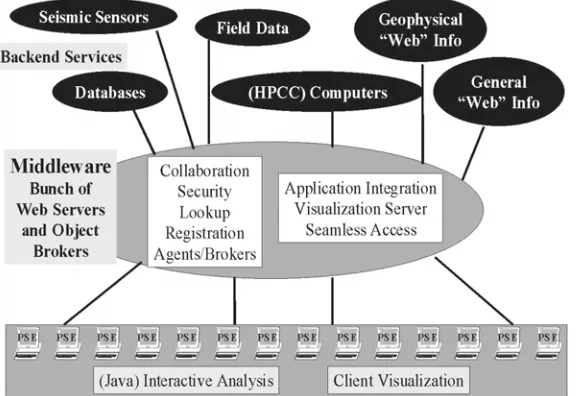
[image:2.595.55.344.380.578.2]GEMCI illustrated in Figure 1, is an Object Web PSE and has the classic three-tier (client, server, re-source) structure of most modern distributed systems. In GEMCI, everything is a “distributed object” whether it be a simulation on a su-percomputer, the basic GEM Web pages, the notes from a field trip en-tered on a palm top, CNN real-time coverage of the latest earthquake or the data streaming in from sensors. GEMCI provides an integrated view of these diverse resources with XML definitions for the raw objects themselves and the data they pro-duce. The services shown in Figure 1, from collaboration, security, object discovery, visualization and computer access, are generic to all computing portals. Building GEMCI using the same approach and tools as other portals en-sures the availability of these services. They will require customization as for instance there are many different visualization packages and each requires non-trivial work to include in such a por-tal. Again, collaboration corresponds to sharing distributed objects, and this can currently only be automated for some objects. Many web pages can be shared using generic techniques but sharing say the control and output of a general simulation can require quite a lot of custom modifications.
Figure 1: GEM Computational Environment
the program on one or more machines, specify the input files and either specify output files or ac-cess them as streams of data in the fashion of UNIX pipes. Each distributed object technology has a rather different approach to this using what is termed an IDL or Interface Definition Lan-guage and specialized Java and C++ code to implement the wrapping.
We can use the concept of the Pragmatic Object Web to simplify this process. Our strategy is to define all relevant properties of computer programs in XML as illustrated in Figure 2.
The properties such as those in figure 2, are used to generate the needed object wrappers, either statically or dynamically. This approach requires the user specify what they know – the properties of their program – while the filter copes with the ob-scure syntax of each object model. Obviously this also allows one to support all object models – COM CORBA, and Java – by changing the filter. In this way one can adapt to changes in the commercial infra-structure used in the middle tier.
One must apply the XML object definition strategy to all entities in GEMCI; programs, instruments and other data sources and repositories. This gives the metadata defining macroscopically the object structure. In addition, one needs to look at the data stored in, pro-duced by or exchanged between these objects. This data is itself a typically a stream of objects, each an array, a table or more complex data structure. One could choose to treat the data at some level as an unspecified (binary) “blob” with XML defining the overall structure but detailed input and output filters used for the data blobs. As an example, consider the approach that an electronic news organization could take for their data. The text of news flashes would be defined in XML but the high volume multimedia data (JPEG images and MPEG movies) would be stored in bi-nary fashion with XML used to specify <IMAGEOBJECT> or <MOVIEOBJECT> metadata.
Figure 2: XML used to describe a GEM program with execution and data files
Systematic use of XML allows use of a growing number of tools to search for, manipulate, per-sistently store and render the information. It facilitates the linkage of general and specific tools/data sources/programs with clearly defined interfaces. This will help the distributed GEM collaborators to separately develop programs or generate data, which will be easily able to inter-operate. In general XML specifies content while say HTML specifies how to view it on a web page. In constructing web pages for any project, always use XML not HTML.
More generally XML standards will be defined hierarchically starting with distributed informa-tion systems, then general scientific computing and finally applicainforma-tion specific object specifica-tions. For example GEMCI would develop its own syntax for seismic data sensors but could build on general frameworks like the XSIL scientific data framework developed by Roy Williams at Caltech (http://www.cacr.caltech.edu/SDA/x-sil/index.html). XSIL supports natural scientific data structures like arrays and the necessary multi-level storage specification.
MathML or providing graphical user specification of mathematical formulae. This could be used in sophisticated implementations of the Complex Systems and Pattern Dynamics Interactive Rapid Prototyping Environment with scripted client side specification of new analysis methods. One can also use MathML in high level tools allowing specification of basic differential equa-tions that are translated into numerical code.
3: Typical Computational Problems for GEMCI
Here we give sample scenarios, which would correspond to distinct problem solving environ-ments built using GEMCI.
3.1: Seismicity Models and Data Assimilation
Our first example of how the GEMCI might be used is drawn from an attempt to create a com-puter model of the seismicity of California or other seismically active region. Such a model, to the extent that it is realistic, could be quite useful in guiding intuition about the earthquake proc-ess, and suggesting new measurements or lines of inquiry.
Making such a model realistic requires many different types of data and there are for instance already substantial archives accumulated by the Southern California Earthquake Center (SCEC), as well as the Seismological Laboratory of the California Institute of Technology, and the Pasa-dena field office of the United States Geological Survey. The relevant data includes:
1) Broadband seismic data from the TERRASCOPE array. 2) Continuous (SCIGN) and “campaign style” geodetic data.
3) Paleoseismic data collected on the major faults of southern California. 4) Near field strong motion accelerograms of recent earthquakes.
5) Field structural geology of major active faults.
6) Other data including GPS data, leveling data, pore fluid pressure, in situ stress, heat flow, downhole seismic data, multi-channel seismic data, laboratory measurements of mechanical properties of various rocks, 3-D geologic structure, gravity data, magneto-telluric data, hydrology data, and ocean tide data (to constrain coastal uplift).
These will be used, for example, to update the fault geometry models used by GEM, and to up-date fault slip histories used to valiup-date earthquake models. Systematic use of XML and a suite of data processing programs built around these standards will be necessary. All data streams should have a defined XML realization (although for efficiency it could be transported in a dif-ferent form). All analysis programs should be built around XML formatted input files rather than “comma-separated”, “8F10.4” or binary formats. This will promote reusability of programs and enable well-defined data exchange.
3.2: Response to an Earthquake in Southern California
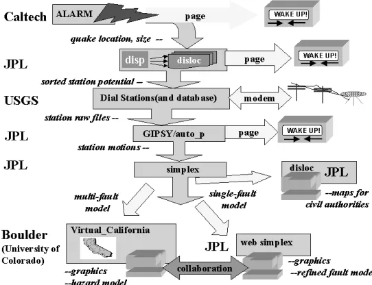
An illustrative scenario is shown in the first part of Figure 3, which links multiple datasets, modeling codes, research centers and scientists for real-time earthquake response. Other data types and models (eg., seismic and field data) would be included in any operational system, but are omitted here for purposes of exposition. The goal is to form a rapid consensus among re-searchers concerning the characterization of the deformation field and the location, size, and di-rection of slip on a fault following an earthquake. This consensus can be used to guide decisions on both civil and scientific responses to the quake.
users via email and pagers. The information on location and magnitude could then be automati-cally used to define an area wherein instruments might be expected to record a signal (the pro-gram disp). Data from these stations would be given priority in retrieval and analysis. In this ex-ample we will assume that the data in question is GPS data from the Southern California Inte-grated Geodetic Network (SCIGN) array. Retrieval in this case is done by telephone modem. As soon as the list of possibly affected stations has been generated, the database at the USGS is checked. If any of the stations on the list have not had data downloaded since the quake, com-puters at the USGS begin dialing the selected stations and retrieving the data.
Data from these stations would then be processed for rapid analysis to determine the measured dis-placements of the stations (program
GIPSY). If the measured displace-ments are large enough, emergency and scientific personnel are notified via email and pager. These dis-placements are then automatically fed into an inversion routine (pro-gram simplex) which solves for the best fit single fault displacement. This single fault displacement is in turn fed back into a forward elastic half space model, which yields a preliminary map of displacements over the whole area (program dis-loc).
[image:5.595.65.336.191.399.2]At this point this map is shared between various scientists and emergency personnel, using one of the emerging suite of web-based collaboration systems that allow the collaboration and interaction of multiple people view-ing and manipulatview-ing the same data set over the Internet. The emergency personnel can use the preliminary map in combination with a Geographical Information System data about utilities, lifelines, etc. to help assign resources to various areas. The scientists will use the preliminary map to help design a strategy for collecting additional measurements. They can also collaborate on refining the single fault model, possibly breaking the single preliminary fault into several segments, introducing more realistic material properties, or including more data, before rerunning the inversion. Here the ability to access GEMCI from any client will be important; in a real-time event many key personnel may only have access to GEMCI from a wireless hand-held device. GEMCI supports not only this but collaboration between a control room with a large screen dis-play and experts viewing aspects of the event on their palm device. Collaboration systems share XML specified objects with each client receiving the most appropriate display. XML specifies the object; this generates HTML for conventional web pages and WML for hand held systems.
Figure 3: Typical Real-time Scenario for Earthquake Analysis Environment
are currently several competing models for this, consensus will undoubtedly involve multiple runs of multiple models and significant discussion among scientific colleagues.
Each of these models as well as the various pieces of the automated processes described above have been developed by different people under different assumptions, and is developed, run, and maintained on computers under the control of the developer. The middleware technologies such as CORBA and Enterprise Javabeans, allow appropriate access and security mechanisms in this complex evolving distributed system.
The 1999 Izmit Turkey earthquake provided a recent example of how a system like this could have been useful. Following that earthquake, many geoscientists got together in a series of con-ference telephone calls to try to piece together what had happened, and what was an appropriate response. Some participants initially only knew what had been reported in the media. Others knew of specific pieces of data concerning the earthquake or of actions being taken by various groups and individuals. It is safe to say that no one had a complete picture. Much of the confer-ence call was devoted to informing everyone about all the pieces of data and all the various initia-tives that people were pursuing or might pursue. Similar calls and emails occurred after the 1992 Landers and 1994 Northridge earthquakes. Having a system such as has been described above wherein participants could share maps, descriptions, programs, data sets, and graphs and wherein they could interactively and collaboratively manipulate the data and programs, both synchro-nously and asynchrosynchro-nously, would immeasurably aid the rapid and accurate diagnosis of what has happened and what should be done next.
3.3 Fundamental Computational Science Studies in Earthquake
Forecasting
Above we described a relatively complicated real-time analysis scenario. Another important problem-solving environment supports that process typically used in computational science. Here the main steps are development of simulation codes, refinement of analysis techniques, ini-tiating runs with multiple parameter values, and comparison of results with multiple data sets. This type of analysis has similarities with the previous two scenarios but now the collaboration for instance would not emphasize real-time issues so much but extend over many months or years. Technically this implies the need for powerful asynchronous tools linking over greater spans of time and space than the tightly coupled scenario of Section 3.2. The tools needed here include the interactive rapid prototyping environment supporting pattern analysis and visualiza-tion. This aspect entails somewhat different trade-offs than the core simulations, in that interac-tivity is perhaps more critical than performance. This could suggest that this part of the problem-solving environment would be implemented client-side using interpretative languages. We would also need to experiment with many different ways of linking programs together and so we would have to support both program development and execution. The real-time constraints of Section 3.2 would on the other hand emphasize execution of pre determined program modules.
This problem-solving environment would naturally link with that in Section 3.1 as GPS, InSAR and broadband seismic (TERRASCOPE) data, together with archived and newly developed pa-leoseismic data could be used in conjunction with the simulation capabilities to establish the rele-vant model parameters.