Abstract: The widely researched area in communication systems is wireless technology. The study of communication systems is incomplete without understanding the operation of the antennas. In the recent years of development in communication systems the important needs are lightweight, compact and cost-effective antennas that are capable of maintaining high performance over a wide spectrum of frequencies. This technological trend has focused much effort into the design of a Micro strip patch antenna, because they will provide high frequency and less bandwidth. This paper presents a design and simulation of rectangular micro strip patch antenna at 2.5 GHz frequency range for wireless communication that provides a radiation pattern along a wide angle of beam. The designing process uses the Rogers RT/duriod 5880 material is used as the substrate and coaxial probe feed method is used to gives the excitation value of the antenna compare with FR4 Epoxy. This antenna has many practical applications like WLAN, WI-FI, etc. so the HFSS software is used to design and implement the antenna.
Keywords: Micro strip patch antenna, Radiation pattern, Ansoft HFSS (High Frequency Structural Simulator).
I.INTRODUCTION
The world of transmission starts with the basic need antennas. In recent years there is a need for more compact antennas due to the announcement devices sizes are decrease rapidly. The micro strip antenna is one of the small size antennas and is printed openly on the printed circuit board. Micro strip antenna is a narrow band and wide beam antenna element pattern in a metallic trace bounded in dielectric substrate. The Federal Communication Commission specified some rules for Ultra Wideband system communication; it has authorized the use of UWB communication in the frequency band of 2.5 GHz. Radar systems have been used for various applications such as monitoring and remote sensing. Radar remote sensing techniques have become interesting to researchers. Ultra Wideband radar system based on the transmission of short duration pulses. The principle of this radar is transmitting a short duration pulses and then detecting the reflected pulse response.
Revised Manuscript Received on March 08, 2019.
Gnanamurugan.S,Research scholar, Anna University, Chennai, India.
Sivakumar.P, Professor, Dept of ECE, Karpagam College of Engineering, Coimbatore, India.
K. Ramash Kumar, Professor, Department of Electrical and Electronics Engineering, Karpagam College of Engineering, Coimbatore, India.
S. Balakumar, Department of Electrical and Computer Engineering, Institute of Technology, Arba Minch University, Etothipa. Karpagam College of Engineering, Coimbatore, India
The microstrip UWB antennas is one of the most commonly used antennas in radar applications. Geometric shape of a microstrip antenna comprises a radiating element on the dielectric substrate and on the other side a ground plane, as illustrated in Fig 1 The most common is rectangular element. The antenna characteristics like the radiation pattern, gain, directivity, VSWR, Return loss and polarization are found by using the Ansoft HFSS simulator tool.
II.ANTENNA STRUCTURE
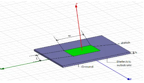
[image:1.595.311.542.456.590.2]Micro strip patch antenna consists of a radiating patch on one side of the dielectric substrate which has a ground plane on the other surface and the patch is from the top side. The micro strip patch antenna consists of three layers these are the bottom layer, which constitutes the ground plane, the middle layer which shows the substrate and as a final point the top layer which shows the patch. The patch is generally made of conducting material such as copper or gold and can take any possible shape. The general structure of the micro strip patch antenna was shown in figure 1.
Fig. 1 Structure of Micro strip patch antenna III. MICRO STRIP PATCH ANTENNA DESIGN
AND CONSIDERATIONS
The Micro strip antenna was deliberate by using the Ansoft HFSS. It is one of the designing tools of antenna. The Ansoft HFSS is a simple and low cost tool which has the simple measures to design the antenna in a very efficient way. By using this software the antenna should be designed and simulated. By simulating this antenna we can get the frequency response, gain, directivity and radiation pattern.
On the Performance of Rectangular Microstrip
Patch Antenna using Rogers RT/Duriod 5880
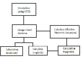
Fig. 2 Design flow of Micro strip patch antenna The Micro strip antenna was designed by using the Ansoft HFSS. It is one of the designing tools of antenna. The Ansoft HFSS is an easy and low cost tool which has the simple procedures to design the antenna in a very well-organized way. By using this software the antenna should be designed and simulated. By simulating this antenna we can get the frequency response, gain, directivity and the radiation pattern. There are many analyzing methods are there in the antenna from these we use the transmission line analyzing method for the antenna design, which includes a lot mathematical calculations in the antenna design. The design flow of the micro strip antenna was shown in figure 2. Based upon these flow they should be designed.
a. Calculation for the Antenna Width (W)
The Width of micro strip patch antenna is given by eqn (1) 0
1
2
2
rC
W
f
(1) Where, C is velocity of light, f0 is a resonant frequencyand ɛr is a relative die electric constant. Other widths are
also chosen but for the higher widths the radiation efficiency is lower in manner and for the lower widths the radiation efficiency is larger in resulting values, in this equation we substituting C=3*10^11mm/s, ɛr =2.2 and f0= 2.8GHz
frequency, finally by solving this equation we get the width value as 42mm for the 2.8GHz.
b. Calculating the Height of the Antenna
The height (H) of the antenna is given by eqn (2) and is written as 0
0.3
2
rC
H
f
(2)By substituting all the values and solving the equation we get the height of the antenna as 3.86mm for 2.8GHz or the standard height of the micro strip patch antenna 3.2mm is used for the simulation.
c. Calculating the Antenna Length (L)
Calculating the length of the micro strip antenna follows the several steps which should be have four steps these as follows as
1) Effective Die Electric Constant
Before calculating the length of the antenna we must calculate the several other computations, the first we would find the effective die electric constant of the substrate which
is much greater than the unity value. The effective die electric constant value is much closer than the die electric constant of the substrate. The effective die electric constant value is given in eqn (3)
1 2
1
1
1 12
2
2
r r reh
w
(3)By substituting all the values and solving the equation we get the effective die electric constant value as 2.03mm for 2.8GHz.
2) Extensive Length
The tangential fields of an antenna are in phase and combine they will produces the maximum radiation pattern along with its two sides of the antenna. The micro strip antenna are looks larger in size when compared to its actually size due to its fringing fields so the length of the antenna was extended by its two sides along a path distance of ∆L and it is given in eqn (4)
(
0.3)(
0.264)
0.412
(
0.258)(
0.8)
re re
w
h
L
h
w
h
(4) By substituting all the values and solving the equation we get the extensive length of the antenna as 1.67mm for 2.8GHz.3) Effective Length of the Antenna
The effective length of the of antenna is given eqn (5) and which helps to find the original length of the rectangular micro strip patch antenna and it is written as
0
2
eff reC
L
f
(5) This should be calculated for the narrow bandwidth of the antenna structure and various parameters of the antenna.By substituting all the values and solving the equation we get the effective length of the antenna as 43.97mm for 2.4GHz frequency range and 37.58mm for 2.8GHz.
d. Actual Length of the Antenna
The actual length of the antenna should be calculated by substituting the effective length and the extensive length of the antenna is given in eqn (6)
2
effL
L
L
(6) By substituting all the values and solving the equation we get the length of the antenna as 39.89mm for 2.4GHz and 34.25mm for 2.8GHz.
IV. ROGER RT/DURIOD 5880(TM)
The Roger material has the die-electric constant value as 2.2 which will be mostly recommended material for the designing of the micro strip patch antenna [1].
pattern along its transmission side of the structure. By using these materials the entire structure of the antenna gets minimized, cost of the designing procedure is getting compact and the same time we get output of the micro strip patch antenna in a good and accurate manner.
V. SOFTWARE TOOL
The software used for the simulation and model of the antenna is HFSS (High Frequency Structural Simulator). It is one of the antenna design tools and it is a high presentation full-wave electromagnetic field simulator for the 3D volumetric passive device. It has simple procedure for the designing of the micro strip patch antenna structure and also it is low cost, high performance and easily understandable software for everyone.
VI. SIMULATIONS AND RESULTS
[image:3.595.349.544.50.181.2]The design and analysis of the rectangular MSA was designed at a frequency range of 2.5GHz. The rectangular antenna has a greatest advantage than other types because they have easily designed structure and have positive radiated edges on the mutually sides of the antenna. The three dimensional view of the simulated micro strip patch antenna was shown in figure3. The radiation pattern of the antenna is shown in figure 4 and figure 5 for 2.5 GHz. From the results will show the improved radiation pattern and the frequency response of the antenna.
Fig. 3 Three dimensional view of antenna i. Radiation Pattern
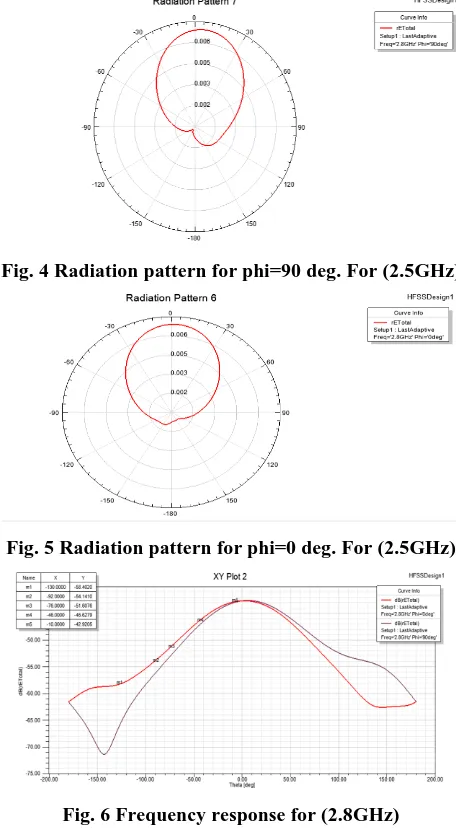
[image:3.595.311.539.56.470.2]The radiation pattern of the patch antenna was plotted as shown in Figure-4 and 5. It has shown that the distribution of power radiation around the antenna as a function of direction represented by the π angle at 2.5GHz. The radiation pattern of an antenna has a typical radiation distribution to its surface and it gives a picture nature of the importance and direction of radiation, by which the antenna emits or receives the electromagnetic waves. The best way to represent radiation pattern is by the three dimensional chart. The radiation pattern is plotted to show the mental picture or provide a view of the radiation. Its magnitude depends on the patch antenna surface. Another way to represent it, is by the angular or polar coordinates. Figure-4 and 5 show the elevation pattern for designed antenna at phi=0 and 90 deg.
Fig. 4 Radiation pattern for phi=90 deg. For (2.5GHz)
Fig. 5 Radiation pattern for phi=0 deg. For (2.5GHz)
Fig. 6 Frequency response for (2.8GHz) ii. Gain
The Frequency response of 2.5GHz show in the fig: 6 to develop frequency of long distance communication. The gain of an antenna is define as the ratio between the highest radiation intensity in a given direction to the highest radiation intensity from a reference antenna in the same direction, the achieved gain of the micro strip patch antenna is 9.8475 dB for 2.8GHz, where the figure 7 show the gain of the antenna.[7]
[image:3.595.49.289.397.514.2] [image:3.595.305.545.545.831.2]iii. Directivity
The directivity is a convenient way to measure the range of power conveyance in a specific direction. The figure 8 shows the directivity of the antenna it is defined as the ratio between the maximum radiation intensity to the average radiation intensity of the antenna, the achieved directivity of the micro strip patch antenna is 9.3172 dB for 2.8GHz.[7][8]
Fig. 8 Directivity for (2.5GHz) iv. Realized Gain
The realized gain is the gain taking into the account the reflection losses at the input of the antenna in other words it is the ratio of power radiated to the power input to the antenna. The figure 9 and figure 10 shows the realized gain of the antenna is 7.3693 dB for 2.5GHz frequency range.[7]
Fig. 9 Realized Gain for (2.5GHz) v. Polarization
The divergence of a stimulating field is defined in terms of the direction of its electric field vector. If the electric field vector is always in one plane, then it is said to be linearly polarized.[8]
[image:4.595.331.523.90.369.2]Fig. 10 Polarization for (2.5 GHz)
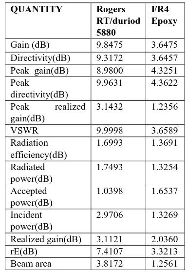
Table. 1 Micro strip patch antenna parameters for 2.5GHz Frequency range compare with Rogers
RT/duriod 5880 and FR4 Epoxy
QUANTITY Rogers
RT/duriod 5880
FR4 Epoxy
Gain (dB) 9.8475 3.6475
Directivity(dB) 9.3172 3.6457
Peak gain(dB) 8.9800 4.3251
Peak
directivity(dB)
9.9631 4.3622
Peak realized
gain(dB)
3.1432 1.2356
VSWR 9.9998 3.6589
Radiation efficiency(dB)
1.6993 1.3691
Radiated power(dB)
1.7493 1.3254
Accepted power(dB)
1.0398 1.6537
Incident power(dB)
2.9706 1.3269
Realized gain(dB) 3.1121 2.0360
rE(dB) 7.4107 3.3213
Beam area 3.8172 1.2561
vi. VSWR
Another way to see how mush may system is matched, VSWR can be used. VSWR is the ratio between the highest voltage and lowest voltage in the transmission line,[7] can
be defined as follows: , where is
the magnitude of .When the system is matched the reflection coefficient approaches 0, while VSWR approaches to 1.
Fig.11 VSWR for (2.5GHz) VII.CONCLUSION
The frequency response, radiation pattern are obtained, the designed antenna gain value is 8.8911 rem, directivity value is 9.9895rem and 3.1121rem for 2.5GHz, the polarization of the antenna is linearly polarized antenna for both the frequency ranges.
REFERENCES
1. R.Nagendra, T.Venkateswarulu “Design and development of compact
microstrip patch dual band antenna for wireless applications”, Alexandria University, Alexandria Engineering Journal (ELSEVIER), 5-May 2017.
2. L. Chandiea and K. Anusudha,“Performance Analysis of Pentagon
Shaped Microstrip Patch Antenna”, IEEE International Conference on Computer,Communication and Signal Processing -2017.
3. Haq Nawaz and Ibrahim Tekin,“Double Differential Fed, Dual
Polarized Patch Antenna with 90dB Interport RF Isolation for 2.4GHz In-Band Full Duplex Transceiver”-IEEE 2017.
4. Houda Werfelli, Khaoula Tayari, Mondher Chaoui, Mongi Lahiani,
Hamadi Ghariani,“Design of Rectangular Microstrip Patch Antenna”, in 2nd International Conference on Advanced Technologies for Signal and Image Processing(ATSIP) -March 2016.
5. Vasujadevi Midasala, .P. Siddaiah “Microstrip Patch Antenna Array
Design to improve Better Gains” in Interational Conference on Computational Modeling and Security, Procedia Computer Science 85-2016.
6. T. Srisuji and C. Nandagopal,“Analysis on Microstrip Patch Antennas
for Wireless Communication”,IEEE Sponsored 2nd International Conference on Electronics and Communication System-2015.
7. S Gnanamurugan , Dr.P.sivakumar “Performance Enhancement Of
Micro Strip PatchAntenna For Wireless Applications” International Journal of Pure and Applied Mathematics, Volume 118 No. 20 2018, 465-471
8. S Gnanamurugan , Dr.P.sivakumar “Performance Analysis Of
Rectangular Micro Strip Patch Antenna For Wireless Application using FGPA ” Artificial Intelligence for cloud-based internet of Things (IOT) in Autosoft Journal (Accepted paper)
9. S.Sinan Gultekina, Dilek Uzera, Ozgur Dundar “A Microstrip Patch
Antenna Design for Breast Cancer Detection”, World Conference on Technology, Innovation and Entrepreneurship(ELSEVIER)-2015.
10. Dhivya N, Pooja Jayakumar, Prashanth Mohan, Rekha Zacharia,
Vishnupriya Vasudevan, G. Prabha" Comparative Study Of Slotted Microstrip Antenna Fed Via A Microstrip Feed Line" Proceedings of 1st IRF International Conference, Coimbatore, 9th March-2014.
11. Ameneh Nejati, Ramezan Ali Sadeghzadeh, Fatemeh Geran, “Effect of
Photonic Crystal and Frequency Selective Surface Implementation on Gain Enhancement in the Microstrip Patch antenna at Terahertz Frequency in Physica B449-2014.
12. Chandrasekhar Rao, A.TathaBabu, S.Haritha, K.Suresh, Gopi,
“Performance analysis of slotted rectangular patch antenna using co-axial and strip line feed” in IJREAT volume 1, issue 3 – July 2013.
13. Werfelli Houda, Mondher Chaoui, Hamadi Ghariani, and Mongi
Lahiani. "Design of a pulse generator for UWB communications", 10th International Multi-Conferences on Systems Signals & Devices 2013 (SSD13), 2013.
14. Atinder pal singh, Ravinder Kumar, HatejSingh Dadhwal,”Design of
edge fed rectangular micro strip patch antenna for WLAN applications using Ansoft HFSS” in VSRD – IJEECE, volume 2,Issue 4 – April 2012.
15. A. Chen, Y. Zhang, Z. Chen, C. Yang, Development of a Ka-Band
Wideband Circularly Polarized 64-Element Micro strip Antenna Array With Double Application of the Sequential Rotation Feeding Technique, IEEE Antennas and Wireless Propagation Letters, Vol. 10, 2011.
16. Mustafa K. Taher Al-Nuaimi and William G. Whittow " On The
Miniaturization of Microstrip Line-Fed Slot Antenna Using Various Slots" Final author version. IEEE Loughborough Antennas and Propagation Conference (LAPC), Loughborough, UK, 2011.
17. A. Chen, Y. Zhang, Z. Chen, S. Chao, A Ka-Band High Gain
Circularly Polarized Micro strip Antenna Array, IEEE Antennas and Wireless Propagation Letters, Vol. 9, 2010.
18. Mahdi Ali, Abdennacer Kachouri and Mounir Samet "Novel method for planar microstrip antenna matching impedance", Journal Of Telecommunications, May 2010.
19. Aruna Rani, R.K. Dawre "Design and Analysis of Rectangular and U Slotted Patch for Satellite Communication" International Journal of Computer Applications , December 2010.
20. Severn Shelly, Joseph Costantine, Christos G, Christodoulou, Dimitris
E. Anagnostou, James C.Lyke “IEEE antennas and wireless propagation letters” volume 9, 2010.
21. Yong-Xin Guo; Kah- Wee Khoo; Ling Chuen Ong "Wide band
Circularly Polarized Patch Antenna Using Broadband Baluns "Antennas and Propagation, IEEE Transactions on Volume 56, Issue2, Feb. 2008.
Mr.S.GNANAMURUGAN has obtained
B.E., (ECE) Degree from SKP
Engineering College in Tiruvannamalai. India.(Anna University Chennai, India) in 2008 and completed his M.E (VLSI DESIGN) from Arunai College of
Engineering (Formally Kamban
Engineering College) in Tiruvannalamai. India. (Anna University Chennai, India) in 2011.He is presently working as Assistant Professor of ECE, Vivekanandha College of Engineering for Women, Thiruchengode, India. He is Having 8 years of Academic Experience. He is a Life Time Member of ISTE and Life Time Member of ISSE (Indian Society of Systems for Science & Engineering, His areas of interest are Wireless Communication and VLSI. He has published more than 13 journals and 13 conference papers. Currently, he is pursuing his Ph.D. degree in the information and communication engineering Dept. at Anna University, Chennai, India.