International Journal of Innovative Technology and Exploring Engineering (IJITEE) ISSN: 2278-3075, Volume-8 Issue-10, August 2019
Internet Enabled Remote Control Device for Air
Conditioners
K. R. K. Sastry, P. Praveen Kumar
ABSTRACT: Traditional infrared air conditioner remote control range is confined to a maximum of 10 meters. When mercury soars users set very low temperature of AC Unit, resulting in Electricity consumption and discomfort. To improve AC remote control range and to provide a comfort temperature of the user, a solution of Internet Enabled Remote Control Device for Air Conditioners is proposed. The user, while commuting or at home, sets the air conditioner (AC) unit to a desired temperature best suited for the individual. The remote controller, according to the user set parameters Travel time, Set temperature, operates the AC unit. An algorithm is developed to control the AC considering the Ambient Temperature and the above two parameters to keep the room temperature desired by the user when user reaches the destination. The user gets the information about the Temperature values issued by the AC remote control. This design is validated on an in-house developed Xilinx Field Programmable Gate Array (FPGA) board.
Keywords― Field Programmable Gate Array (FPGA), Node MCU, Internet of Things (IoT), Slice register, air conditioner (AC) unit, ambient temperature, Infra Red (IR).
I. INTRODUCTION
Internet of Things (IoT) connects the Internet and things in smart spaces. By the implementation of intelligence with sensing devices, IoT is applied widely to the fields such as smart homes. The application fields in smart homes implement smartness into home areas for comfort and Power saving. People require comfort and convenient life in smart homes. Home automation is essential for IoT based Smart homes. [1].
Home appliances such as AC, TV, video players, home theater, room lighting control use different remote controls for controlling the appliances, (select items , change of status). [2].
The electrical appliances can be remotely controlled from anywhere in the world using IoT technology and the smart phones. IoT improves the issue of Range that is faced in Infrared (IR), Bluetooth technology. [8]. IR based remote controllers are used for home automation applications such as lighting, temperature control, security and door management [3].
A novel communication protocol is proposed to control devices with more than just switching functionality [4]. A Remote control unit for controlling air conditioner with a radio frequency, provided by original manufacturer can be used to control another appliance such as TV set by changing the software. [9].
Revised Manuscript Received on August 05, 2019.
K. R. K. Sastry Received his B.E degree in 1986 in Electronics and communication Engineering, Andhra University, Visakhapatnam, India.
P. Praveen Kumar Received his B.Tech degree in 2015 in Electronics and communication Engineering, JNT University, Kakinada, India.
In order to store and send specific IR instructions to Smart IR learning module, it is to be wirelessly
controlled by the commands. The IR instructions can be integrated for IR-Controlled appliances into a single module and the users could use the mobile for controlling the appliances such as TV, DVD, air conditioner etc. [10]. The proposed solution implements an Internet of Things (IoT) based design consisting of a Xilinx FPGA and Node MCU unit (with built in Wi-Fi stack) to control AC Unit and to monitor the ambient temperature. An Algorithm is developed to meet the user set temperature in an optimal way. The AC unit could be controlled while the user is commuting or the user is at his premises.
In section II, a system overview of the implementation is introduced. Section III describes the remote controller engine block diagram. Section IV describes the Temperature controlling algorithm. Section V presents the simulation results. Section VI shows the Hardware Setup and results. Section VII gives the Conclusions. Section VIII deals with the Future Scope.
II. SYSTEM OVERVIEW
The System Functionality diagram is shown below in the Fig.1.
cloud
Remote Controller Engine Node
MCU
AC Unit IR
LED WiFi Router
GUI
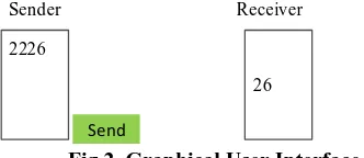
Fig.1. System Functionality diagram A. Mobile
A smart phone with Android operating system is used to send the user commands: the Travel Time, the Set Temperature, other Parameters like swing control, fan mode etc.
B. GUI
The user sends the control commands through a Graphical User Interface (GUI). The commands use a custom format between the mobile and the FPGA system. GUI is a web page created with a server. It is a free server space and a free sub domain.
2226
26 Sender Receiver
Internet Enabled Remote Control Device for Air Conditioner
[image:2.595.56.222.82.154.2]Send
Fig.2. Graphical User Interface (GUI)
The GUI has a sender and receiver dialog boxes. The sender dialog box sends the Travel Time and the Set Temperature parameters to the Remote controller engine. Assuming that the maximum travel time is within an hour in most of the cities, the Travel Time range is considered 0 to 59 min. The Set Temperature range for the AC unit is 16 to 28⁰C.
The receiver dialog box displays the current temperature executed by the remote controller unit.
C. Wi-Fi Router
The authorized person accesses the Internet within a maximum range of 40 meters.
D. Node MCU(ESP8266)
It has an inbuilt Wi-Fi stack and accesses the data from the cloud and communicates with the Remote Controller Engine via a Serial communication link.
E. Remote Controller Engine
It controls the IR driver LED for sending appropriate commands and sends the current temperature to the user.
III. REMOTE CONTROLLER ENGINE
The functional diagram is shown in Fig.3.
Clock Generator Tx. Command
Memory IR
Driver
Tx. Command Select
Temp Sensor Serial
Interface
[image:2.595.58.273.441.556.2]Temperature Contoller Algorithm
Fig.3. Block Diagram of Remote Controller Engine
Serial Interface:
It sends the current temperature set by the AC Unit and receives the Parameters (Set Temperature and Travel Time) from the Node MCU with a Baud Rate of 9.6 kbps.
Transmit command memory:
A command library is developed to control Lloyd Split AC unit. The command data is stored in on-chip ROM. The bit ON, OFF periods, the Lloyd AC data format is used [5]. The data width 69 bits, carrier frequency 38KHz, Preamble ON period 9ms, Preamble OFF period 4.5ms.
After transmission of initial 36 bits of data over IR driver, the output is off for a period of 13.5 ms (Total Preamble time). Subsequently rest of the 33 bits is transmitted [6]. Transmit Command Select:
It analyzes the user commands for the limits, fetches the temperature command from the Transmit Command
Memory and receives the dwell time from the Algorithm. Dwell time is time interval between successive AC temperatures commands (0 indicates no command). Clock Generator:
It generates logic for a clock of 38 KHz signal, 9600 baud rate clock from the on board 50 MHz crystal generator. Temperature Sensor:
A 2 pin on board device sends the ambient temperature (with 0.5⁰C accuracy) to the FPGA.
Temperature Controlling Algorithm:
It selects the appropriate command from the Memory block, Serializes the data and drives the IR LED.
IV. TEMPERATURE CONTROLLING ALGORITHM
An algorithm is developed to optimally control the room temperature equal as the user set temperature within the commuting time of the user.
When the user wants the home to maintain 24⁰C, and the sensors reports the temperature as say 30⁰C, then the controller runs the appliance to lower the temperature to maintain 240C. A user connects the home server via internet for controlling the appliance. The home server upon receiving the user commands generates necessary IR control signal. After receiving IR control signal, the appliance responds accordingly [7].
The algorithm uses the following parameters
1. Initial ambient temperature.(Temperature sensor output) 2. Set temperature. (User sets)
3. Commuting time. (User sets)
Initial ambient temperature is the room temperature before the algorithm starts. The maximum value of 38⁰C is considered as outside temperature is normally less than 52⁰C.
The Algorithm consists of 4 categories given below: (a). Ambient Temperature >33°c to ≤ 38°c and Travel Time 15min to <1hr.
(b). Ambient Temperature >28°c to ≤ 33°c and Travel Time 15min to <1hr.
(c). Ambient Temperature >33°c to ≤ 38°c and Travel Time 0 min to <15 min.
(d). Ambient Temperature >28°c to ≤ 33°c and Travel Time 0 min to <15 min.
The relation between AC Temperature, Set Temperature and Dwell time for category 1 is shown in Table I.
International Journal of Innovative Technology and Exploring Engineering (IJITEE) ISSN: 2278-3075, Volume-8 Issue-10, August 2019
Table I. Dwell Time Table for Category (1)
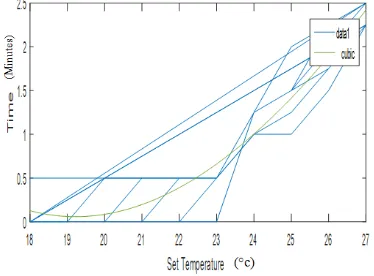
A curve fitting graph for the Table I is realized by a Quadratic equation and a cubic equation fittings graphs using MATLAB software.
The quadratic equation graph gives error >15% so the cubic equation graph (error <5%), is adopted for the algorithm. The cubic equation curve fitting graph for Category (1) is shown in Fig.4 and the cubic equation is
y = 0.006327x3 - 0.33675x2 + 5.9121x – 34.028 (1)
Fig.4. Cubic equation graph for Category (1)
[image:3.595.59.272.73.286.2]The cubic equation curve fitting graph for Category 2, 3 and 4 are shown in Fig. 5, Fig. 6 and Fig. 7 respectively.
Fig.5. Cubic equation graph for Category (2)
[image:3.595.62.275.383.556.2]Fig.6. Cubic equation graph for Category (3)
Fig. 7. Cubic equation graph for Category (4)
The cubic equations for all the four categories are summarized in Table II.
Table II: Cubic Equations Table
Categ ory
Cubic Equation
1
y = 0.006327x3 - 0.33675x2 + 5.912 x – 34.0282 y= -0.00078509x3 + 0.090399x2 - 2.605x + 22.307
3 y = 0.043651x3 - 2.628x2 + 52.654x -350.87
4 y = 0.025072x3 - 1.4879x2 + 29.403x -193.37
The cubic equation can be realized in the hardware with: 1. Digital Signal Processing (DSP) blocks.
2. Look Up Table (LUTs) method.
[image:3.595.74.261.632.770.2]V. SIMULATION RESULTS
The design is developed in Verilog HDL and it is synthesized and simulated using Xilinx 14.3 ISE.
[image:4.595.309.540.53.197.2]The simulation results are shown in Fig. A and Fig. B.
Fig. A. Simulation result for Temperature 20⁰C and
[image:4.595.67.273.114.210.2]Time 11min.
Fig. B. Simulation result for Temperature 23⁰C and Time 31min.
VI. HARDWARE SETUP AND RESULTS
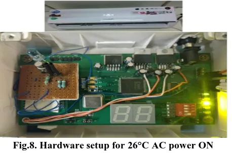
The design is validated on an in-house developed Xilinx FPGA board and the Hardware setup for validation along with the split AC unit is shown in Fig.8.
Fig.8. Hardware setup for 26°C AC power ON condition.
The design is validated on Xilinx xc3s250e-5vq100 in-house developed board and synthesis results are shown in Table III.
Device utilization summary:
Target device:xc3s250e-5vq100
Table III. Device utilization table
No Description used available
1 Number of Slices
Registers 645 4,896
2 Number of bonded IOBs 23 66
3 Number of 4 input LUTs 976 4,896
4 Number of BUFGMUXs 5 24
5 Number of occupied
Slices 761 2,448
6 Number of Slices
containing related logic 761 761
Timing Summary:
Speed Grade : -5 Minimum period : 12.604ns Maximum Frequency : 79.341MHz
Minimum input arrival time before clock : 4.057ns Maximum output required time after clock: 4.134ns
VI. CONCLUSION
In this paper, we proposed an Internet enabled AC remote controller and its architecture in detail. An Algorithm features to meet the user set temperature in an optimal way is explained. The Simulation results and the validation setup on an in-house developed Xilinx FPGA-XC3S250E based board are discussed. Lloyds AC unit is successfully operated by the implemented design. Also validated Voltas AC unit for various operating conditions.
A maximum operating Frequency of 79.34MHz with device occupancy of 645 slice registers is achieved.
VII.FUTURE SCOPE
The proposed work could be extended to operate the household appliances such as Television Remote control, Electric bulb Light intensity, Fan speed, from the remote places. The constrain of Line of sight control of AC unit using IR LED could be improved with wireless protocols like ZigBee, Bluetooth.
REFERENCES
1. Kuen-Min Lee, Wei-Guang Teng, Ting-Wei Hou, “Point-n-Press: An Intelligent Universal Remote Control System for Home Appliances,” IEEETrans. Autom. Sci. Eng.,vol. 13, no. 3, Jul 2016. 2. Laehyun Kim, Wanjoo Park, Hyunchul Cho and Sehyung Park, “A
Universal Remote Control with Haptic Interface for Customer Electronic Devices,” IEEE Trans. Consumer Electron., vol. 56, no. 2, pp. 913-918, May 2010.
3. Taewan Kim, Hakjoon Lee, and Yunmo Chung “Advanced Universal Remote Controller for Home Automation and Security,” IEEE Trans. Consumer Electron., vol. 56, no. 4, pp. 2537-2542, Nov 2010. 4. Ali Ziya Alkar and Umit Buhur “An Internet Based Wireless Home
Automation System for Multifunctional Devices,” IEEE Trans. Consumer Electron.,vol. 51, no. 4, nov 2005.
5. Qi Zhang, “An Intelligent Air Conditioning Control System Based on Mobile Communication Networks,” 2015 12th International Conference on Fuzzy Systems and Knowledge Discovery (FSKD). 6. Ch.Arun prakash,K.R.K. Sastry “ Implementation of Air Conditioner
Infrared Protocol on a Reconfigurable Hardware,” 2018 8th International Conference on Cloud Computing, Data Science & Engineering (Confluence), pp.787-790, Aug 2018.
7. Boyoung Lee, Sojung Yang and Deokjai Choi “A Status Monitoring System Design/Implementation for Home Appliances controlled by home server”2009 First International Conference on Networks & Communications, pp. 220-223, doi:10.1109/NetCoM.2009.21, 2009. 8. Rakesh K. Deore, Vijay R. Sonawane and Pooja H.Satpute “Internet
[image:4.595.61.277.259.381.2] [image:4.595.56.285.474.625.2]International Journal of Innovative Technology and Exploring Engineering (IJITEE) ISSN: 2278-3075, Volume-8 Issue-10, August 2019
9. Ming Wang, Guiqing Zhang, Chengui Zhang, Jianbin Zhang, chengdong Li “An IoT-based Appliance Control System for Smart Homes” 2013 Fourth International Conference on Intelligent Control and Information Processing (ICICIP), pp.744-747, June 9-11, 2013. 10. YAN Wenbo, WANG Quanyu, GAO Zhenwei “Smart Home
Implementation Based on Internet and WiFi technology” Proceedings of the 34th Chinese Control Conference, July 28-30, 2015.
AUTHORS PROFILE
K. R. K. Sastry Received his B.E degree in 1986 in Electronics and communication Engineering, Andhra University, Visakhapatnam, India. He completed his M.Tech in 1989 in OptoElectronics and Opticalcommunications, IIT New Delhi, India. He has Rich industrial experience in Telecomm and VLSI. He has Authored many IP cores in VLSI. His main interests are VLSI based designs and validation. He is currently working as Associate Professor, in the Department of Electronics and communication Engineering, Gayatri Vidya Parishad College of Engineering (Autonomous), Visakhapatnam, India.