Ames Laboratory Publications
Ames Laboratory
5-1-2000
Effects of fatigue-induced changes in
microstructure and stress on domain structure and
magnetic properties of Fe–C alloys
Chester C.H. Lo
Iowa State University, [email protected]
F. Tang
Iowa State University
S. B. Biner
Iowa State University
David C. Jiles
Iowa State University, [email protected]
Follow this and additional works at:
http://lib.dr.iastate.edu/ameslab_pubs
Part of the
Electromagnetics and Photonics Commons
, and the
Engineering Physics Commons
The complete bibliographic information for this item can be found at
http://lib.dr.iastate.edu/
ameslab_pubs/170
. For information on how to cite this item, please visit
http://lib.dr.iastate.edu/
howtocite.html
.
Effects of fatigue-induced changes in microstructure and stress on domain
structure and magnetic properties of Fe–C alloys
Abstract
A study of the effects of microstructural changes on domain structure and magnetic properties as a result of
fatigue has been made on Fe–C alloys subjected to either cold work, stress-relief annealing, or heat treatment
that produced a ferritic/pearlitic structure. The magnetic properties varied with stress cycling depending on
the initial condition of the samples. Variations in coercivity in the initial stage of fatigue were closely related to
the changes in dislocation structure. In the intermediate stage of fatigue the observed refinement of domain
structures was related to the development of dislocation cell structures and formation of slip bands. In the
final stage of fatigue the remanence and maximum permeability decreased dramatically, and this rate of
decrease was dependent on the crack propagation rate.
Keywords
Microstructural properties, Magnetic domain structure, Thermal properties, Annealing, Coercive force
Disciplines
Electromagnetics and Photonics | Engineering Physics
Comments
The following article appeared in
Journal of Applied Physics
87 (2000): 6520 and may be found at
http://dx.doi.org/10.1063/1.372757
.
Rights
Copyright 2000 American Institute of Physics. This article may be downloaded for personal use only. Any
other use requires prior permission of the author and the American Institute of Physics.
Effects of fatigue-induced changes in microstructure and stress on domain structure
and magnetic properties of Fe–C alloys
C. C. H. Lo, F. Tang, S. B. Biner, and D. C. Jiles
Citation: Journal of Applied Physics 87, 6520 (2000); doi: 10.1063/1.372757
View online: http://dx.doi.org/10.1063/1.372757
View Table of Contents: http://scitation.aip.org/content/aip/journal/jap/87/9?ver=pdfcov
Published by the AIP Publishing
Articles you may be interested in
Magnetic properties and microstructure of Nd-Fe-B sintered magnets with DyHx addition J. Appl. Phys. 111, 07A705 (2012); 10.1063/1.3671426
Structural characterization and magnetic properties of steels subjected to fatigue AIP Conf. Proc. 509, 1597 (2000); 10.1063/1.1306224
Magnetic properties and magnetic-domain structures of nanocrystalline Sm 2 Fe 14.5 Cu 0.5 Ga 2 C y Appl. Phys. Lett. 75, 546 (1999); 10.1063/1.124417
Microstructure refinement and improvements of magnetic properties of two-phase exchange-coupled Sm 2 Fe 15 Ga 2 C x /- Fe nanocomposites by additional Zr
Appl. Phys. Lett. 73, 1586 (1998); 10.1063/1.122212
Microstructure and hard magnetic properties of nanocomposite Sm 2 Fe 15 Ga 2 C x permanent magnets with an excess of Fe prepared directly by melt spinning
Appl. Phys. Lett. 72, 1110 (1998); 10.1063/1.120939
Effects of fatigue-induced changes in microstructure and stress on domain
structure and magnetic properties of Fe–C alloys
C. C. H. Lo,a)F. Tang, S. B. Biner, and D. C. Jiles
Ames Laboratory, Iowa State University, Ames, Iowa 50011
A study of the effects of microstructural changes on domain structure and magnetic properties as a result of fatigue has been made on Fe–C alloys subjected to either cold work, stress-relief annealing, or heat treatment that produced a ferritic/pearlitic structure. The magnetic properties varied with stress cycling depending on the initial condition of the samples. Variations in coercivity in the initial stage of fatigue were closely related to the changes in dislocation structure. In the intermediate stage of fatigue the observed refinement of domain structures was related to the development of dislocation cell structures and formation of slip bands. In the final stage of fatigue the remanence and maximum permeability decreased dramatically, and this rate of decrease was dependent on the crack propagation rate. © 2000 American Institute of Physics.关S0021-8979共00兲77008-3兴
I. INTRODUCTION
Magnetic inspection is being developed as one of the few methods for monitoring the progress of fatigue damage in magnetic materials. Consistent trends throughout the fa-tigue life of different materials have been observed using either magnetic hysteresis properties or Barkhausen effect signals.1–3The quantitative variation of these magnetic prop-erties with number of stress cycles is dependent on the initial microstructural conditions of the materials and the fatigue conditions such as the stress or strain amplitude.4
II. EXPERIMENTAL DETAILS
Three series of samples with the same nominal compo-sition共Fe–0.2 wt % C兲were processed in one of the follow-ing ways: 共1兲 cold worked, 共2兲 cold worked followed by stress-relief annealing at 500 °C for 1 h, and共3兲heat treated at 905 °C for 2 h and then furnace cooled. The cold-worked samples had fine carbides共average size 1.7m兲and degen-erate pearlites in a ferrite matrix, while the heat-treated samples had a ferrite/pearlite structure with a volume frac-tion of pearlite 9.4% and an average ferrite grain size 29m. All samples were machined to an ‘‘hour glass’’ shape, care-fully ground and electropolished to obtain a smooth surface finish. During a fatigue test samples were strained at a fre-quency of 2 Hz with a fixed strain amplitude ⌬⑀⫽0.22%. The fatigue test was halted at predetermined intervals at a strain level⑀⫽0.2% in order to perform magnetic measure-ments. In situ measurements of magnetic hysteresis were car-ried out using a surface sensor. Surface plastic replicas were prepared and examined by scanning electron microscopy 共SEM兲to study the changes in surface microstructure.
The changes in dislocation structure of the cold-worked and heat-treated samples as a result of fatigue were studied by transmission electron microscopy 共TEM兲. Series of samples were fatigued for predetermined numbers of cycles and were then sectioned. TEM specimens were prepared by jet polishing followed by ion-beam milling, and were
exam-ined using a Philips CM30 TEM. The magnetic domain structure of the samples was imaged by magnetic force mi-croscopy 共MFM兲. The samples were electropolished to re-move stress that can alter the surface domain structure.
[image:4.612.345.527.372.698.2]III. RESULTS AND DISCUSSION
Figure 1 shows the variations in the magnetic hysteresis properties with expended fatigue life. The fatigue life of a
a兲Electronic mail: [email protected]
FIG. 1. Plots of共a兲coercivity Hc, 共b兲remanence Br, and共c兲maximum
permeability m as functions of expended fatigue lifetime for the
cold-worked, stress-relieved, and heat-treated samples.
JOURNAL OF APPLIED PHYSICS VOLUME 87, NUMBER 9 1 MAY 2000
6520
0021-8979/2000/87(9)/6520/3/$17.00 © 2000 American Institute of Physics
sample can be divided into three stages according to the changes in magnetic properties. In stage I共about the first 5% of fatigue life兲 the coercivity Hc decreased for the cold-worked and stress-relieved samples but increased for the heat-treated sample. However the remanence Br and maxi-mum permeability m were found to increase for all samples. In stage II 共about 5%–80%兲Hc, Br, and m re-mained stable. In stage III 共the last 10%–20%兲 Br andm decreased significantly, and these parameters were found to decrease at a higher rate for the stress-relieved sample than for the cold-worked and heat-treated samples.
The variations in Hc can be interpreted in terms of the changes in dislocation structure. As Fig. 2共a兲 shows, the cold-worked sample initially had clusters of highly dense dislocations. In the sample that was fatigued for 100 stress cycles significant rearrangement of dislocations had already taken place 关Fig. 2共b兲兴as a result of the motion and annihi-lation of the pre-existing dislocations. This led to the forma-tion of dislocaforma-tion tangles 关the dark bands in Fig. 2共b兲兴, be-tween which were regions with dislocation densities lower than those found in the originally cold-worked structure. The reduction in dislocation density in the cold worked sample caused the impedance to domain wall movement共and hence, Hc) to decrease in the initial stage of fatigue. In the heat-treated sample the dislocation density was found to increase significantly during this stage关Figs. 2共d兲and 2共e兲兴. This re-sulted in higher resistance to domain wall motion and hence an increase in Hc. Dislocation cell structures were observed
in both the cold-worked and heat-treated samples after they had been fatigued to the saturation stage. The former was found to have a more irregular dislocation cell structure than the latter 关Figs. 2共c兲 and 2共f兲兴. The average dislocation cell sizes were measured to be 1.5 and 3.2 m for the cold-worked and heat-treated samples, respectively. The forma-tion of fine and ragged dislocaforma-tion cells in the cold-worked sample is due to the fact that the sample initially had a higher dislocation density. Rearrangement of the dislocation struc-ture as a result of cyclic stress was impeded by the fine carbides present in the sample.
The changes in dislocation structure of the samples are also manifested in their mechanical properties. Figure 3 shows the stress amplitude applied to the samples along the field direction to maintain constant strain amplitude condi-tions when the fatigue test was halted for magnetic measure-ments. In stage I the stress amplitude was found to decrease by 26% and 16% for the cold-worked and stress-relieved samples, respectively. This indicates that in the former a larger reduction in dislocation density occurred and accounts for the larger decrease in Hcof the sample in this stage. The smaller change in stress amplitude found in the stress-relieved sample is attributed to the stress-relief anneal that gave rise to a lower residual stress level and smaller dislo-cation density in the sample before fatigue. The changes in stress amplitude also affect the magnetic properties due to the magnetomechanical effect. It has been reported in previ-ous studies that both Brandmfirst increased with increas-ing tensile stress along the applied field direction. They then decreased when the applied tensile stress was increased be-yond a certain value 共lower than the yield strength兲due to the stress-induced anisotropy along the field direction.5,6The increase in Brandmof the cold-worked and stress-relieved samples in stage I 关Figs. 1共b兲 and 1共c兲兴 could therefore be due to the reduction in residual stress from a high level re-sulting from fatigue softening of the initial structures.
[image:5.612.80.271.50.339.2]The stress-relief anneal was also found to affect the variations in magnetic properties in the final stage of fatigue. During this stage both Br and m decreased significantly. The high dislocation density associated with the microscopic fatigue cracks formed at the sample surface and the stress concentration at crack tips led to strong domain wall pinning. After a macroscopic fatigue crack had formed it propagated
FIG. 2. TEM micrographs showing the dislocation structure of the cold-worked sample at different stages of its fatigue life:共a兲before fatigue,共b兲 fatigued for 100 cycles共0.2% expended fatigue life兲,共c兲fatigued for 3000 cycles共6.9%兲, and the dislocation structure of the heat-treated sample共d兲 before fatigue,共c兲fatigued for 100 cycles共0.4%兲, and共f兲fatigued for 3000 cycles共10.8%兲.
FIG. 3. Plot of the stress levels ⌬for a fixed strain amplitude of⌬⑀of 0.22% at different stages during fatigue lifetime for each of three groups of samples.
6521
J. Appl. Phys., Vol. 87, No. 9, 1 May 2000 Loet al.
[image:5.612.347.530.50.181.2]into the sample. As a result of both Br andmdecreased as the crack area increased. The demagnetizing effect of the fatigue crack2also led to formation of closure domains near the crack. This resulted in an increase in Barkhausen emis-sion signal during the final stage of fatigue. This is consistent with results reported in a previous study.3
The demagnetizing effect induced by the crack made it more difficult to magnetize the sample to saturation.7 The higher rate of decrease of magnetic parameters such as Br and m found in the stress-relieved sample was due to its higher fatigue crack growth rate measured in the SEM rep-lica study (2.8⫻10⫺6 m/cycle in the stress relieved sample compared with 2.4⫻10⫺7 m/cycle for the cold-worked sample兲. The higher fatigue crack growth rate of this sample is attributed to the stress-relief anneal that removed the re-sidual compressive stress which could have helped retard the propagation of the fatigue crack.8
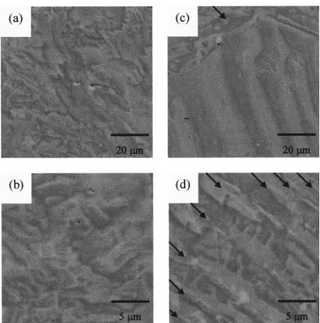
It was found in the MFM study that the magnetic domain structure of the samples changed with fatigue. Figure 4共a兲 shows a complex domain structure typical of those observed in the cold-worked sample, which is characterized by do-mains with widths of 5–10 m and wavy domain walls. Formation of this pattern could be caused by the presence of irregular, highly dense dislocation clusters that pin the do-main walls. In the cold-worked sample dodo-main volumes
were significantly smaller when it was fatigued to failure, with sizes ranging from 1 to 5m关Fig. 4共b兲兴. An important observation is that this domain scale is close to the size of the dislocation cells observed in the TEM study. The present result suggests that the domain walls could be pinned mainly at the dislocation cell walls, and therefore the domain struc-ture and magnetic hysteresis properties should be dependent on the dislocation cell size. As shown in Fig. 1共a兲, in the saturation state of fatigue Hcremained stabilized at a higher level for the cold-worked sample than for the heat-treated sample. This could be attributed to the smaller dislocation cell size found in the former that gives rise to stronger do-main wall pinning than that in the latter.
In the heat-treated sample a domain structure was ob-served with larger domain sizes 共widths of 10–20m兲than in the cold-worked specimen关Fig. 4共c兲兴. Supplementary do-mains 共indicated by the arrow兲 were also seen in the grains which probably contain slightly misoriented surfaces 共i.e., the angle between the surface and the closest easy axis of magnetization is less than a few degrees兲. In these grains the basic domain pattern is similar to that observed in the lower part of Fig. 4共c兲and the formation of supplementary domains helps reduce the stray field energy.9 In the sample fatigued for 100 cycles a domain structure with smaller domains was observed. This could be due to the increase in dislocation density and the formation of dislocation tangles. In the sample that was fatigued to failure slip band intrusions and extrusions were observed, and domains with size from 2 to 5
m were commonly found 关Fig. 4共d兲兴. These observations support the results of a previous study which show that the Barkhausen effect signal decreases with increasing numbers of stress cycles during stage II of fatigue.3The formation of slip bands refines the domain structure and hinders the do-main wall motion in the surface layer. As the number density of slip bands increased with fatigue cycle the domain wall jumps became smaller, resulting in smaller amplitude Barkhausen effect signals.
ACKNOWLEDGMENT
This work was sponsored by the National Science Foun-dation, Division of Civil and Mechanical Structures under Grant No. CMS-9532056.
1M. S. C. Bose, NDT International 19, 83共1986兲.
2Y. Bi, M. R. Govindaraju, and D. C. Jiles, IEEE Trans. Magn. 33, 3928 共1997兲.
3
M. R. Govindaraju, A. Strom, D. C. Jiles, S. B. Biner, and Z.-J. Chen, J. Appl. Phys. 73, 6165共1993兲.
4C. C. H. Lo, F. Tang, D. C. Jiles, and S. B. Biner, IEEE Trans. Magn. 35,
3977共1999兲.
5J. M. Makar and B. K. Tanner, J. Magn. Magn. Mater. 184, 193共1998兲. 6
J. M. Makar and B. K. Tanner, J. Magn. Magn. Mater. 187, 353共1998兲.
[image:6.612.60.289.49.280.2]7Y. Bi and D. C. Jiles, IEEE Trans. Magn. 34, 2021共1998兲. 8G. E. Dieter, Mechanical Metallurgy共McGraw-Hill, London, 1988兲. 9A. Hubert and R. Schafer, Magnetic Domains共Springer, Berlin, 1998兲.
FIG. 4. MFM images showing the domain structure of the cold-worked sample共a兲before fatigue and共b兲after being fatigued to failure. MFM im-ages of the cold-worked sample共c兲before fatigue and共d兲after being fa-tigued to failure. The arrow in共b兲points to a supplementary domain. The arrows in共d兲indicate the positions and orientation of slip band intrusions and extrusions observed on the sample surface.
6522 J. Appl. Phys., Vol. 87, No. 9, 1 May 2000 Loet al.