Int. J. Electrochem. Sci., 11 (2016) 9917 – 9927, doi: 10.20964/2016.12.21
International Journal of
ELECTROCHEMICAL
SCIENCE
www.electrochemsci.org
NiCoP Nanoparticles as Efficient Electrocatalyst for Oxygen
Evolution Reaction in an Alkaline Solution
Yuhao Li*, Yanping Tian, Yuhua Yan, Haizhou Chang, Ruizhuo Ouyang and Yuqing Miao* University of Shanghai for Science and Technology, Shanghai 200093, P. R. China.
*
E-mail: [email protected], [email protected]
Received: 19 August 2016 / Accepted: 26 September 2016 / Published: 10 November 2016
Water splitting can acquire clean energy. To enhance the water splitting ability, electrocatalysts qualify high catalytic ability and low cost are need to be explored. Herein, a bimetal phosphide (NiCoP) nanomaterial is reported as an efficient electrocatalyst for water oxidation. The ternary nickel cobalt phosphide nanoparticles were synthesized from the solution-phase reaction of organic Co and Ni precursors with trioctylphosphine. The nanoparticle size is 18 ± 5 nm. After annealing, the catalytic ability of NiCoP is significantly enhanced. The overpotential decreased from 480 to 330 mV vs RHE at 10 mA cm-2 in 1 mol dm-3 KOH alkaline solution. When hydrophilic carbon nanotubes (CNTs) mixed with the NiCoP to form hybrid NiCoP-CNTs, the overpential further decreased from 330 to 320 mV vs RHE at 10 mA cm-2. The Tafel slopes of ca. 69 and 52 mV are found for annealed NiCoP and NiCoP-CNTs, respectively. The stability test of NiCoP-CNTs also shown the remarkable catalytic activity for long-term operation.
Keywords: NiCoP, bimetal phosphide, electrocatalyst, water oxidation
1. INTRODUCTION
Water splitting is an ideal way to obtain clean renewable hydrogen and oxygen for energy applications. Water splitting reactions contain two half-reactions, the hydrogen evolution reaction (HER) and the oxygen evolution reaction (OER) [1-3]. Four electrons need to be transferred in the kinetically sluggish oxygen evolution reaction (4OH− → O2 + 2H2O + 4e− in alkaline media) to obtain
O2 [1]. To enhance the OER efficiency, noble metal catalysts, such as ruthenium and iridium oxides,
are often used as water oxidation catalysts [4, 5]. However, the scarcity and high price of these noble metal catalysts limit their application in water splitting.
(CoOx[20] andNiOx[21]), sulfide (NiSx)[22] and phosphide nanomaterials (CoP[23-25] and Ni2P[26,
27]) have all been reported as excellent catalysts for OERs. Recently, multi-transition metal nanomaterials, including multi-metal hydroxides[28] and bimetal phosphides (NiCoP[29-31], CoMnP[32] and CoFeP[33]), have been shown to have a synergistic catalytic effect. This has attracted significant interest for the development of new bimetal nanocatalysts.
Previously, Ni2−xCoxP nanoparticles were synthesized and reported by the hot-solution reaction,
the composition, size, and morphology can be controlled [34]. Further, NiCoP nanoparticles have also been reported by hydrothermal combined with high temperature phosphorization method [30, 31]. Ni foam as an excellent supporter, which provided a high specific surface area. These hybrid nanomaterials presented remarkable electrocatalytic ability. Inspired by the bimetal synergistic catalytic effect, and carbon nanotubes (CNTs) as a remarkable electronic conductor, we suspected that if CNTs were introduced into the NiCoP system, the catalytic ability could be improved. Herein, we report a CNTs assisted NiCoP nanosystem for the fabrication of a NiCoP-CNTs hybrid nanomaterial system. The synthesized system presented a good catalytic performance for water oxidation. After annealing nanoparticles and mixing with CNTs, the overpotential decreased from 480 to 330 and 320 mV vs reversible hydrogen electrode (RHE) at 10 mA cm-2 for annealed NiCoP and NiCoP-CNTs respectively. The Tafel slopes were found ca. 69 and 52 mV in a 1 mol dm-3 KOH alkaline solution respectively.
2. EXPERIMENTAL
2.1. Reagents and materials
Tri-n-octylphosphine (TOP, 90%) was purchased from Alfa Aesar. Nickel (II) acetylacetonate (Ni(acac)2), cobalt(II) acetylacetonate (Co(acac)2), and oleylamine (OAm, 90%) were purchased from
Adamas. 1-Octadecene (ODE) was purchased from Acros. Cyclohexane and ethanol were purchased from SCRC. Nafion (5%) was purchased from Sigma-aldrich. Multi-wall carbon nanotube (CNTs, dim. 20-40 nm, length 1-2 μm) was purchased from TCI. Ni-foam (surface mass density, 280 g cm-2, PPI, 110, aperture, 0.1 mm) was purchased from Suzhou Taili Ltd, China. ITO glass (6 Ω) was purchased from Shenzhen Huanan Xiangcheng Ltd, China. Ultrapure water was used in all the manipulations (resistivity = 18.2 MΩ. cm-1
). All chemicals were used as received.
2.2 Synthesis of Ni2P, Co2P and NiCoP nanoparticles
Ni2P and Co2P nanoparticles was synthesized according to the literature reported method with
some modifications [35]. For NiCoP, typically, Ni(acac)2 (128 mg, 0.5 mmol), Co(acac)2 (128 mg, 0.5
and then rapidly heated to 320 oC and maintained for 2 h under argon protection. After cooling to room temperature, the black precipitate was collected and washed with a mixture of cyclohexane and ethanol by centrifugation (10000 rpm, 15 min) to afford NiCoP nanoparticles.
2.3 Synthesis of hydrophilic carbon nanotubes (CNTs)
Hydrophilic CNTs were synthesized according to the literature reported method with some modifications [36]. 30 mg CNTs was dissolved in a 30 mL 30% HNO3 a.q. solution and then
ultrasonic dispersion for 15 min. The mixture was further refluxed for 24 h. After cooling to room temperature, the black precipitate was collected and wash with deionized water to neutral pH. Finally, the hydrophilic CNTs were dried by frozen drying and which can be easily dispersed in water.
2.4 Ink Preparation
The synthesized nanoparticles (NPs, 20 mg) were only or mixed with hydrophilic CNTs (mass ratio, 1:1) in ethanol and sonicated for 30 min. Then 5 wt% Nafion solution were added and followed by sonicating for at least 30 min. 15 μL of catalysts ink was deposited on the ITO glass electrode or Ni foam electrode (loading: 1.0 mg cm-2) and dried at room temperature.
2.5 Characterization
Transmission electron microscope (TEM) and electron microscopy energy dispersive spectroscopy (EDS) were performed using a FEI Tecnai F20 S-Twin. Scanning electron microscope (SEM) and electron microscopy energy dispersive spectroscopy (EDS) were performed using a Tescan VEGA3. Powder X-ray diffraction (XRD) was carried out on a Bruker D8 advance X-ray diffractometer using the Kα line of a Cu source. Samples were deposited onto a zero background quartz holder, and data were acquired in the 2θ range 30-80° with a step size of 0.02°. XRD patterns compared to powder diffraction files (PDF’s) from the ICDD database. X-ray photoelectron spectroscopy (XPS) samples were deoxygenated under Ar and investigated on a Thermo Scientific K-Alpha system (Al, Kα, hν = 1486.6 eV). Elemental analysis (ICP-OES) was recorded on a Thermo Scientific iCAP 7200.
2.6 Electrochemical Measurements
An CHI 760D electrochemical workstation (CH Instruments, Shanghai, China) with conventional three-electrode setup was used to record all the electrochemical information. In a typical experiment, a standard three electrode setup was employed using an Ag/AgCl reference electrode, a Pt wire auxiliary electrode, and a ITO glass working electrode (surface area = 0.25 cm2) using a 1 mol·dm-3 KOH solution as the solvent (pH = 13.6). The surface of the ITO glass electrode was modified by depositing 15 μL of nanoparticle ink onto the surface and followed by drying under 37 o
for 10 min. The LSV curves were measured at a scan rate of 50 mV s-1. The potentials were measured versus Ag/AgCl and converted to the reversible hydrogen electrode (RHE) by using equation 1. The resistivity of the solution was determined using the iR compensation feature of the CHI software and corrections were performed manually according to equation 2.
ERHE = EAg/AgCl + 0.197 + 0.059pH (1)
ERHE = EAg/AgCl + 0.197 + 0.059pH – iR (2)
3. RESULTS AND DISCUSSION
3.1 Characterization of CoNiP nanoparticles
Nanostructured NiCoP was synthesized using a method similar to that reported for bimetal phosphide nanomaterials [29, 34, 35]. We also synthesized Ni2P and Co2P nanoparticles for
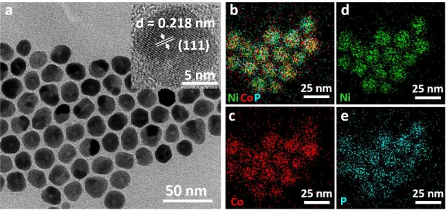
electrocatalytic studies [7, 35]. As shown in Figure 1a, after washing with cyclohexane and ethanol, small roundish hollow nanoparticles were analyzed by TEM. As a result of 1-octadecene and oleylamine, as long carbon chain ligands, being self-assembled on the particle surfaces, these small roundish nanoparticles could easily be dispersed in common organic solvents (e.g. cyclohexane, hexane, dichloromethane and chloroform). The average diameter of the NiCoP particles was ca. 18 ± 5 nm. The formation of hollow NiCoP nanoparticles can be explained via a nanoscale Kirkendall pathway [7, 35].
Figure 1. (a) TEM image of NiCoP nanoparticles (inset: the corresponding magnified TEM image. The element maps of NiCoP nanoparticles (b) and the distribution of contained elements Ni (d, green), Co (c, red), and P (e, cyane).
[image:4.596.136.461.454.607.2]
EDS data, the atomic ratio of Ni, Co and P was close to 1:1:1.2. The slight excess of P is attributed to the TOP as the surface ligand binding on the NiCoP.
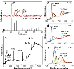
To further confirm the Co/Ni/P ratio and crystalline phase structure, the synthesized NiCoP nanoparticles was characterized by X-Ray Diffraction (XRD) (Figure 2a). Appreciable diffraction peaks at 2θ = 41.01°, 44.95°, 47.59° and 54.57°were found. By comparing to the hexagonal structure of NiCoP (PDF#71-2336, 2θ = 40.99°, 44.90°, 47.58° and 54.44°), we could see that the synthesized NiCoP peaks were well-matched, and could be attributed to the (111), (201), (210) and (300) crystalline phases, respectively. No extraneous peaks were found, indicating that the as-synthesized NiCoP is a hexagonal system. According to the Bragg equation, crystal lattice spacing (d) and 2θ have a relationship. By checking the inset of the NiCoP high resolution TEM image (Figure 1a), a crystal lattice spacing of ca. 0.218 nm can be found, which is consistent with the corresponding (111) plane of NiCoP (d = 0.220 nm). Therefore, the 2θ values and crystal lattice spacing also demonstrated that the NiCoP bimetal phosphide structure had been produced.
Figure 2. (a) Powder XRD pattern of NiCoP nanoparticles (red) and the standard pattern of NiCoP (black, PDF:71-2336). The XPS spectra of NiCoP (b), and the High-resolution XPS regions of Co 2p (c), Ni 2p (d), and P 2p (e).
[image:5.596.157.446.329.598.2]
777.88 and 792.78 eV were assigned to the Co 2p3 and 2p1 energy levels, respectively. Similar peaks at around 852.58 and 869.78 eV were also found and assigned to the Ni 2p3 and 2p1 peaks, respectively. By checking the satellite peak fitting ratio of the Co 2p3 and Ni 2p3 peaks, some oxidized Co and Ni species were also located and they were found to be mixed with neutral Co and Ni, respectively. For the P 2p region in Figure 2e, the peak at 129.48 eV could be assigned to the P 2p3 region, another peak at 869.78 eV could also be assigned to the small amounts of oxidized P species formed on the surface of the bimetal phosphide. As the sample was exposed to air, these oxidized elements on the nanoparticle surfaces could be ascribed to the presence of oxygen in the sample. Oxygen was also confirmed by the XPS survey spectrum [37, 38].
3.2 Electrochemical performance of NiCoP
In general, the crystalline phase is the most important factor for determining the catalytic ability of a material [39]. The water oxidation ability of NiCoP was evaluated by electrochemical experiments in an alkaline solution (1 mol dm-3 KOH, pH = 13.6) using a standard three-electrode system. NiCoP nanoparticles were loaded onto an indium tin oxides (ITO) glass plate (1 mg cm-2 with Nafion) as the working electrode. The ohmic potential drop (iR) losses arising from the solution resistance were all corrected for. Usually, the potential of the current density reaching 10 mA cm-2 is defined as the overpotential for heterogeneous water oxidation catalysts [4]. As shown in Figure 3a, the linear sweep voltammetry (LSV) curve of NiCoP exhibited an overpotential of 480 mV vs RHE (please note that all the potentials in this article are vs RHE) at a current density of 10 mA cm-2, accompanied by a large amount of gas bubbles on the surface of the working electrode. To confirm that the gas bubbles were oxygen, a fluorescence-based oxygen sensor was used. The lowest onset overpotential of ca. 290 mV was achieved for the NiCoP nanomaterial, which is comparable to many metal oxide or metal phosphide based water oxidation catalysts [24, 25, 27, 29, 30, 32].
Figure 3. LSV curves of unannealed (a) and annealed (b) NiCoP without and with CNTs, Ni2P, and
Co2P loaded on the bare ITO glass electrode (blank).
The bare ITO electrode (blank) exhibited low OER activity. The synthesized Co2P exhibited
[image:6.596.131.462.529.662.2]
Ni2P. The acquired Ni2P overpotential value was similar to the reported one.[27] Thus, NiCoP had a
lower overpotential relative to Co2P and Ni2P, which could be attributed to Co having a higher OER
activity than Ni and the synergism between the two metal centers. It has been suggested that the thermodynamic barrier of a proton-coupled electron transfer pre-equilibrium can be decreased by insetting a second metal while facilitating O-O bond formation, leading to enhanced catalytic activity [40].
Compared with the reported different bimetal phosphide[29, 30, 32, 33], the synthesized NiCoP electrocatalysts presented higher overpotential. This could be attributed to surface ligands of nanoparticles block the interaction between catalyst and H2O, and also block the active sites on the
surface of nanocatalyst [16, 41]. So these nanomaterials have been annealed at 450 oC under the protection of Argon with 5% H2 to remove the surface ligands. ICP-OES was used to double check the
composition of NiCoP. The atoms ratio of Ni/Co/P showed nearly 1:1:1, indicating no ligands of TOP, oleylamine, and octadecene on the surface of NiCoP. As shown in Fig 3b, all nanomaterials presented much higher catalytic activity than unannealed one. For NiCoP, the overpotential decreased from 480 mV to 330 mV. The overpotential of Co2P and Ni2P also decreased to 350 mV and 430 mV,
respectively. The decreased overpotential demonstrated that more surface active sites of nanomaterial were exposed by removing the surface ligands.
[image:7.596.206.387.509.662.2]It is well known that carriers can enhance the catalytic ability of catalysts. By simply mixing the carrier with the catalysts, the electroconductivity and stability can also be improved. CNTs, as excellent catalytic carriers, have been used previously [12]. In this work, we mixed NiCoP with CNTs (mass ratio, 1:1) to investigate the catalytic ability. In Figure 3a and 3b, the overpotential was monitored at 460 and 320 mV, which decreased 20 and 10 mV for the unannealed and annealed NiCoP catalysts without adding CNTs. For annealed NiCoP, when the current density was reached to 30 mA cm-2, the overpotential decreased from 350 to 330 mV. The decreased overpotential demonstrate that mixing CNTs with catalyst can enhance the catalytic ability.
Figure 4. Tafel plots of unannealed NiCoP and annealed NiCoP with and without CNTs.
respectively. After mixing the CNTs and annealed NiCoP, the Tafel slope apparently decreased from 69 to 52 mV. It is interesting to note that bi-metal phosphide NiCoP had a similar Tafel slope to the reported Co-based OER catalysts, and even better than reported NiCoP nano materials [23-25, 27, 30, 32, 33, 42]. Therefore, CNTs supported NiCoP is an excellent noble metal free OER catalyst.
3.3 Stability performance of NiCoP
[image:8.596.205.393.399.547.2]Catalytic durability is a crucial factor for water oxidation. Ni foam is an excellent catalyst supporter and has a three-dimensional net structure. Catalysts can be loaded on it and they are unlikely to fall off. Herein, NiCoP-CNTs were loaded on the Ni foam working electrode for the durability study through chronoamperometry [11, 43]. I-t curves are shown in Figure 5, which recorded the current density changing of the NiCoP catalyst. We set a constant voltage 0.60 V vs Ag/AgCl to make the starting current density at 22 mA cm-2. The current density increased in the first 40 min and then slowly decreased to 20 mA cm-2. This increased current density also can be found in the other phosphides, which could be tentatively attributed to the process of activation at the beginning of catalytic process [11]. After 10 h, the catalyst maintained 91% current density, which suggests that NiCoP-CNTs exhibit remarkable stability in the long term electrochemical process.
Figure 5. I-t curves of NiCoP-CNTs loaded on the Ni foam, inset is the enlarged I-t curves.
Interestingly, we found a 10 h I-t curve with a regular jagged line and the current density periodically pulsed. As shown in the inset of Figure 5, the magnified I-t curve clear shows this regular changing, which could be explained by the generated oxygen adsorption and desorption from the surface of the catalyst surface. When NiCoP oxidized water to generate oxygen, the O2 accumulated
O2 could not easily block the interaction between catalyst and water, which was beneficial to the
long-term operation of the catalyst.
As the Ni foam surface covered with NiCoP-CNTs and the catalyst surface oxidation was monitored and demonstrated on the most reported metal phosphide catalysts, i.e. CoP[23, 24], Ni2P[26,
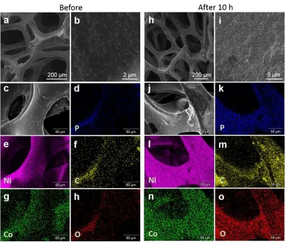
27] and CoMnP[32], we tentatively ascribed catalyst surface oxidation as the main reason for the decreased current density. We used the SEM to check the changing of Ni foam surface topography and elemental composition. In Figure 6a, b, h and i, the Ni foam surface coated a layer of NiCoP-CNTs, which was uniform, compact and no apparent defect. After 10 h catalytic process, the surface of Ni foam became rough, and the compact surface layer appeared unconsolidated net structure. The topography changing means the surface has been etched and changed. Further, the changing of surface elemental composition was also confirmed. In Figure c-h and j-o, the oxygen percentage increased from 3.23% to 13.97%, meaning the surface oxidation process happened during the catalytic process. The monitored atom ratio of Co/P from ca. 1:1 to 2:1, which means phosphide was partly oxidized to phosphorus oxide (POx or P−O species), and partly etched into solution and the surface could form metal oxide. The increased oxygen percentage is in line with the recent reported surface oxidation of phosphide electrocatalysts during the catalytic process [26, 27, 32].
[image:9.596.94.508.358.708.2]
4. CONCLUSIONS
The NiCoP nanomaterial has been reported for water oxidation in alkaline solution. The NiCoP structure has been systematically investigated. The electrochemical results showed that the NiCoP nanomaterial has a higher activity than Ni2P and Co2P nanomaterial, meaning that bimetal phosphide
qualifies synergistic effect. After annealing nanoparticles, the overpotential decreased from 480 to 330 mV. The Tafel slope was also decreased from 75 mV to 69 mV. This enhanced catalytic ability can be ascribe to the more exposed surface active sites. After mixing CoNiP with CNTs, the overpotential and Tafel slope further decreased to 320 mV and 52 mV, respectively, which also certified that CNTs improved the catalytic ability. The durability study revealed that NiCoP is catalytically active for long-term operation. Thus, our results demonstrated that bimetal phosphide has a high catalytic ability, which could be attributed to the bimetal synergistic catalytic effect or the CNTs improved conductivity. These results provide a new research strategy for further developing noble metal free phosphide catalysts for usage in OERs.
ACKNOWLEDGMENT
This work was financially supported by NSFC (21501121), the China Postdoctoral Science Foundation (2015M581635), and the special financial grant from the China postdoctoral science foundation (2016T90376).
References
1. X. Zou, Y. Zhang, Chem. Soc. Rev., 44 (2015) 5148.
2. J. Ran, J. Zhang, J. Yu, M. Jaroniec, S. Qiao, Chem. Soc. Rev., 43 (2014) 7787.
3. Y. Miao, L. Ouyang, S. Zhou, L. Xu, Z. Yang, M. Xiao, R. Ouyang, Biosens. Bioelectron., 53 (2014) 428.
4. C.C.L. McCrory, S. Jung, J.C. Peters, T.F. Jaramillo, J. Am. Chem. Soc., 135 (2013) 16977. 5. F.A. Frame, T.K. Townsend, R.L. Chamousis, E.M. Sabio, T. Dittrich, N.D. Browning, F.E.
Osterloh, J. Am. Chem. Soc., 133 (2011) 7264.
6. E.J. Popczun, C.W. Roske, C.G. Read, J.C. Crompton, J.M. McEnaney, J.F. Callejas, N.S. Lewis, R.E. Schaak, J. Mater. Chem. A, 3 (2015) 5420.
7. J.F. Callejas, C.G. Read, E.J. Popczun, J.M. McEnaney, R.E. Schaak, Chem. Mater., 27 (2015) 3769.
8. Z. Huang, Z. Chen, Z. Chen, C. Lv, M.G. Humphrey, C. Zhang, Nano Energy, 9 (2014) 373. 9. E.J. Popczun, C.G. Read, C.W. Roske, N.S. Lewis, R.E. Schaak, Angew. Chem. Int. Ed., 53 (2014)
5427.
10.M. Xiao, D. Yang, Y. Yan, Y. Tian, M. Zhou, M. Hao, R. Cheng, Y. Miao, Electrochim. Acta, 180 (2015) 260.
11.Y. Shi, Y. Xu, S. Zhuo, J. Zhang, B. Zhang, ACS Appl. Mater. Interfaces, 7 (2015) 2376. 12.Y. Pan, W. Hu, D. Liu, Y. Liu, C. Liu, J. Mater. Chem. A, 3 (2015) 13087.
13.Z. Huang, Z. Chen, Z. Chen, C. Lv, H. Meng, C. Zhang, ACS Nano, 8 (2014) 8121.
14.E.J. Popczun, J.R. McKone, C.G. Read, A.J. Biacchi, A.M. Wiltrout, N.S. Lewis, R.E. Schaak, J. Am. Chem. Soc., 135 (2013) 9267.
15.M. Xiao, R. Cheng, M. Hao, M. Zhou, Y. Miao, ACS Appl. Mater. Interfaces, 7 (2015) 26101. 16.J.M. McEnaney, J.C. Crompton, J.F. Callejas, E.J. Popczun, A.J. Biacchi, N.S. Lewis, R.E.
17.A. Mendoza-Garcia, H. Zhu, Y. Yu, Q. Li, L. Zhou, D. Su, M.J. Kramer, S. Sun, Angew. Chem. Int. Ed., 54 (2015) 9642.
18.Y. Xu, R. Wu, J. Zhang, Y. Shi, B. Zhang, Chem. Commun., 49 (2013) 6656. 19.E. Muthuswamy, P.R. Kharel, G. Lawes, S.L. Brock, ACS Nano, 3 (2009) 2383.
20.S. Cobo, J. Heidkamp, P.A. Jacques, J. Fize, V. Fourmond, L. Guetaz, B. Jousselme, V. Ivanova, H. Dau, S. Palacin, M. Fontecave, V. Artero, Nat. Mater., 11 (2012) 802.
21.X. Yu, T. Hua, X. Liu, Z. Yan, P. Xu, P. Du, ACS Appl. Mater. Interfaces, 6 (2014) 15395. 22.L. Feng, G. Yu, Y. Wu, G. Li, H. Li, Y. Sun, T. Asefa, W. Chen, X. Zou, J. Am. Chem. Soc., 137
(2015) 14023.
23.J. Chang, Y. Xiao, M. Xiao, J. Ge, C. Liu, W. Xing, ACS Catal., 5 (2015) 6874. 24.C. Hou, S. Cao, W. Fu, Y. Chen, ACS Appl. Mater. Interfaces, 7 (2015) 28412. 25.M. Liu, J. Li, ACS Appl. Mater. Interfaces, 8 (2016) 2158.
26.L.A. Stern, L. Feng, F. Song, X. Hu, Energy. Environ. Sci., 8 (2015) 2347. 27.A. Han, H. Chen, Z. Sun, J. Xu, P. Du, Chem. Commun., 51 (2015) 11626.
28.K. Fominykh, P. Chernev, I. Zaharieva, J. Sicklinger, G. Stefanic, M. Döblinger, A. Müller, A. Pokharel, S. Böcklein, C. Scheu, T. Bein, D. Fattakhova-Rohlfing, ACS Nano, 9 (2015) 5180. 29.C. Wang, J. Jiang, T. Ding, G. Chen, W. Xu, Q. Yang, Adv. Mater. Interfaces, 3 (2016) 1500454. 30.Y. Li, H. Zhang, M. Jiang, Y. Kuang, X. Sun, X. Duan, Nano Research, (2016) 1.
31.A. Han, H. Chen, H. Zhang, Z. Sun, P. Du, J. Mater. Chem. A, 4 (2016) 10195. 32.D. Li, H. Baydoun, C.N. Verani, S.L. J. Am. Chem. Soc., 138 (2016) 4006. 33.A. Mendoza-Garcia, D. Su, S. Sun, Nanoscale, 8 (2016) 3244.
34.D.R. Liyanage, S.J. Danforth, Y. Liu, M.E. Bussell, S.L. Brock, Chem. Mater., 27 (2015) 4349. 35.Y. Pan, Y. Liu, J. Zhao, K. Yang, J. Liang, D. Liu, W. Hu, D. Liu, Y. Liu, C. Liu, J. Mater. Chem.
A, 3 (2015) 1656.
36.W. Li, R. Ouyang, W. Zhang, S. Zhou, Y. Yang, Y. Ji, Y. Yang, K. Feng, X. Liang, M. Xiao, Y. Miao, Electrochim. Acta, 188 (2016) 197.
37.G. Li, D. Zhang, J.C. Yu, Environ. Sci. Technol., 43 (2009) 7079. 38.H. Li, P. Yang, D. Chu, H. Li, Appl. Catal. A: Gen., 325 (2007) 34. 39.Y. Ni, L. Jin, J. Hong, Nanoscale, 3 (2011) 196.
40.Y. Surendranath, M.W. Kanan, D.G. Nocera, J. Am. Chem. Soc., 132 (2010) 16501.
41.J.M. McEnaney, J.C. Crompton, J.F. Callejas, E.J. Popczun, C.G. Read, N.S. Lewis, R.E. Schaak, Chem. Commun., 50 (2014) 11026.
42.I.H. Kwak, H.S. Im, D.M. Jang, Y.W. Kim, K. Park, Y.R. Lim, E.H. Cha, J. Park, ACS Appl. Mater. Interfaces, 8 (2016) 5327.
43.B. You, N. Jiang, M. Sheng, M.W. Bhushan, Y. Sun, ACS Catal., 6 (2016) 714.