Network Services for Distributed Computing
A thesis submitted for the degree of Doctor of Philosophy
of the Australian National University
Wanlei
Zhou
u
STATEMENT
I here by state that this thesis contains only my own original work except where explicit reference has been made to the work of others.
Wanlei Zhou
ACKNOWLEDGEMENTS
First of all, I would like to sincerely thank my supervisor, Dr. Brian Molinari for valuable advising and many discussions. As the Chairman of my Supervisory Panel, he led me into the beautiful field of distributed and parallel computing research, which I feel so bright now. He taught and encouraged me to think and write in English instead of Chinese. After I started to write, he tirelessly read through endless drafts, made them more precise and correct.
I would also like to express my gratitude to Professor Robin Stanton. As one of my supervisors and the Head of the Department, he made valuable comments and guidelines for my research project and provided me with the necessary facilities for the research. I am grateful to Dr. Chris Johnson for being one of my supervisors and I sin-cerely thank him for his many valuable comments and suggestions on my research. I am also deeply indebted to my advisors Dr. John Smith and Dr. Malcolm Newey who have constantly encouraged and helped me in all stages of my research. I thank Dr. Peiyi Tang and Dr. Qing Li for their comments on my thesis writing.
I would also like to thank Apollo Computer Inc. in MA, USA and The ANU for providing me a great opportunity to work and study in the Research and Development Laboratory of Apollo Computer Inc. in Chelmsford, MA, USA for three months. This made me aware of how the large commercial software be developed. I thank Dr. David Ortmayer and Jim Perry of the Domain Distributed Service Group in Apollo Computer Inc. for being my supervisors during my working trip.
I thank our secretaries and programmers in the department, Bev Johnstone, Jean-nie Haxell, David Hawking, Ivan Dean, and Drew Corrigan for their warm smiles and - efficient assistance.
"'111111 J l I
'I
II
II
I
ii
-I thank my friends in the Department of Computer Science, The ANU: Seppo Keronen, Charles Loboz, James Popple, Jimmy Wang, Dan Zhou, Qing Yang, Gavin
Michael, Dharmendra Sharma, and Ely Albacea. To work and talk with these caring friends has always been a graceful experience.
I thank my parents for their love and encouragement. To be a son they can be proud of has always been a driving force in my study towards a Ph.D. degree.
I sincerely thank my wife Ling Wang and my son Lingdi Zhou for being here to
company me. Without their love, patience, support, encouragement, smile. and sacrifices, I would not have completed this dissertation.
iii
-ABSTRACT
In this dissertation we study distributed program systems that involve the remote procedure call (RPC) primitives. In particular, it concentrates on a group of goals which have been attracting the attention of both researchers and practitioners. These goals include: easing the burden of distributed programming, provision of tools for dis-tributed debugging, provision of tools for execution time estimation and provision of services for managing transaction-oriented distributed operations. The dissertation describes the design and construction of the following network services and analytic tools that help to meet the above goals.
1. Tools for the support of rapid prototyping. We address the problem of overcoming the complexity of constructing a distributed program by implementing a set of rapid prototyping tools which can generate RPC program prototypes from user specified description files. We first present a distributed application model. It con-sists of three parts, namely, the user interface, the distributed frame and the appli-cation modules. According to this model, we then provide three kinds of tools to help the generation of each part of a distributed application. These tools are: a dis-tributed frame generator, a user interface generator and an application module generator. Executable versions of the generated programs can be obtained immediately. Interfaces are provided to connect all these generated programs together to form the prototype of the distributed application program. We also pro-vide a case study of using our prototyping tools to develop a moderate size distri-buted system.
2. Distributed debugging tool. Few distributed debuggers provide facilities for RPC-oriented distributed program debugging. We have developed a distributed monitor to help debugging RPC-oriented distributed programs. Our monitor is event-based. We first define primitive events as those things that relate to the RPC cal-ling and process forks. Then we define several operations which are used to con-struct combined events from primitive events or previously defined combined events. The monitor is constructed to automatically record all primitive events and
1 •
iv
-user defined combined events of a RPC-oriented distributed program into an appropriate distributed database. The monitor then determines a partial ordering between events in a same process and in different processes, based on the event timestamps and a notion of cause and effect Finally, the partial ordering is used in replaying the execution of the monitored distributed program.
3. An analytic tool for execution time estimation. One of the important performance Ir metrics for a distributed program is the expected execution time. As servers that export remote I'rocedures of a Rl'C-oriented distributed program are assumed to be dynamically allocated within the whole distributed system, the execution time of a RPC-oriented program varies according to different allocations. So we esti-mate the execution time of a distributed program by averaging over all possible remote procedure allocations. An analytic tool serving such a purpose has been developed. It includes a nondeterministic algorithm for estimating execution time of general RPC programs, the explicit solution for some special cases, and the esti-mation methods for lower and upper bounds of execution time of general RPC programs.
4. RPC transaction manager. In some distributed applications, one may want to asso-ciate transaction semantics with a single RPC call or even a group of RPC calls. Most existing RPC implementations or proposals do not employ transaction con-cept but rather employ at-most-once semantics. We have designed a RPC transac-tion manager based on a model which is suitable for our discussion. The model consists of definitions for RPC operations and rollback operations. At first the RPC transaction manager is designed to manage transactions consisting of a single RPC call. Then the transaction manager is expanded to manage transactions consisting of several parallel executed RPC calls. We also provide informal proofs showing that the tool we designed ensures the transaction characteristics.
V
-Table of Contents
Acknowledgements ... . Abstract ... . List of Figures ... . List of Tables ..... . List of Listings and Algorithms ... . Chapter 1. Introduction ... :.
1.1. llistorical Notes ... . 1.2. Distributed Systems Overview ... . 1.3. Distributed Computing ... . 1.3.1. Client/Server Model and Remote Procedure Calls ... .
1.3.2. Network Computing System ... . 1.3.3. Distributed Application Model ... . 1.4 Problems in Distributed Computing ... ..
1.4.1. Program Development Problems ... .
1.4.2. Management Problems ... . 1.4.3. Other Problems ... . 1.5. Thesis Outline ... . Chapter 2. Tools for Rapid Prototyping ...... ..
2.1. Rapid Prototyping and its Context ... ..
2.1.1. The Life-Cycle Model ... .
1
lll
X
XU
xiii
1
1
4
6
6 8
11
13
13
18
19 20
23
23
23
I
I I
VI
-2.1.2. Computer-Aided Rapid Prototyping ... 25
2.2. Structure of the Prototyping Tools ... 27
2.2.1. The Prototyping Model ... 27
2.2.2. Distributed Calendar: The Example ... ... 30
2.2.3. A Concurrency Primitive ... 31
2.3. Distributed Frame Generator... 32
2.3.1. Syntax ... 32
2.3.2. Semantics ... 34
2.3.3 Implementation ... 37
2.4. User Interface Generator ... 53
2.4.1. Introduction ... 53
2.4.2. Syntax ... 55
2.4.3. Semantics ... 56
2.4.4. Implementation ... 57
2.5. Application Module Generator ... 64
2.5.1. Introduction ... 64
2.5.2. Syntax ... 65
2.5.3. Semantics ... 65
2.5.4. Implementation ... 68
2.6. Interfacing the Generators ... 70
2. 7. Prototyping the Distributed Calendar System ... 71
Chapter 3. Debugging RPC Programs ... 75
3.1. Introduction ... 75
Vll
-3.2. Definitions and Assertions ... .
3.2.1. Primitive Event ... .
3.2.2. Combined Event ... .
3.3. Monitor Structure ... .
3.3.1. Overview ... .
3.3.2. Debugging Library ... .
3.3.3. Managing Server ... .
3.3.4. Controller ... .
3.3.5. Event Definition File ... .
3.4. Trace Analysis ... .
3.4.1. Ordering Events ... .
3.4.2. Process Replay ... .
3.5. An Example ... .
3.6. Remarks ... .
Chapter 4. Execution Time Evaluation ... .
4.1. Existing models and their limitations. . ... .
4.2. The Evaluation Model ... .
4.2.1. Syntactic Issues ... .
4.2.2. Semantic Issues ... .
4.2.3. Performance Measures ... .
4.3. Parallel Block Special Case ... .
4.3.1. Analysis ... .
4.3.2. Explicit Solution ... .
viii
-4.3.3. Comparison Between Calculated and Simulated Results ... 120
4.4. Estimation of Lower and Upper Bounds ... 122
4.4.1. Lower Bound ... 122
4.4.2. Upper Bound ... 123
4.4.3. Simulation Results ... 124
4.5. Applications of the Model ... 126
4.5.1. Example: A Seller-Buyer System ... 126
4.5.2. Example: An Extended Seller-Buyer System ... 127
4.6. Remarks ... 128
Chapter 5. RPC Transaction Management ... 130
5.1. Background and Related Works ... 130
5.2. RPC Transaction Models ... 133
5.2.1. The RPC Model ... 133
5.2.2. Single RPC Transaction Model ... 140
5.2.3. Parallel RPC Transaction Model ... 140
5.2.4. Accessing Servers ... 141
5.3. Single RPC Transaction Management ... 143
5.3.1. The Manager ... 143
5.3.2. Algorithms ... 145
5.3.3. Properties ... 151
5.4. Parallel RPC Transaction Management ... 157
5.4.1. Algorithms ... 157
5.4.2. Properties ... 159
1
ix
-5.5. Remarks ... 160
Chapter 6. Conclusions ... 162 ,
6.1. Summary ... 162
6.2. A Computer Science Perspective ... 163
6.3. Further Research Directions ... 164
I Appendix ... 166
References ...... 182
I
X
-11
List of Figures
1.1. The client/server model 7
1.2. The remote procedure call communication model 8
1.3. Terms used for distributed applications 11
11
-
1.4. The distributed application model 12-
1.5. Network services for RFC-oriented distributed computing 20c;., 2.1. The computer-aided prototyping model 28
2.2. General prototyping process 29
2.3. Input and output of the distributed frame generator 36 2.4. Processing structure of the distributed frame generator 37 2.5. Input and output of the user interface generator 57
2.6. Menu-tree pointers 58
2.7. The menu screens 63
2.8. Input and output files of the application module generator 67
2.9. Generator connections 70
3.1. Events with the same timestamp value 81
3.2. Events relations 87
3.3. The structure of the distributed monitor 89
3.4. RPC communication 100
3.5. Event graph 106
4.1. The relationship among client program, location broker, and servers 108
4.2. Program flowgraph 112
4.3. Flowgraphs of atoms 113
4.4. The flowgraphs of the three block constructors 113
4.5. Nondeterministism of the algorithm 116
Xl
-4.6. Flowgraph of the simple parallel block 117
4.7. Average execution time and simulation results 121
4.8. Flowgraph of a complex RPC program 125
4.9. Simulated execution time and lower and upper bounds when L changes 125
4.10. Flowgraph of the simple example 126
4.11. Structure of the complex example 128
5.1. RPC and its rollback operation 137
5.2. Some possibilities when return is US 138
5.3. Semantics of the single RPC transaction 140
5.4. Semantics of the parallel RPC transaction 141
5.5. Structure of the RPC Manager
5.6. The idea LET table structure
A-1. The architecture of the distributed calendar system
143
153
169
I t
..
I
Xll
-List of Tables
2.1. Output files for ca.def 40
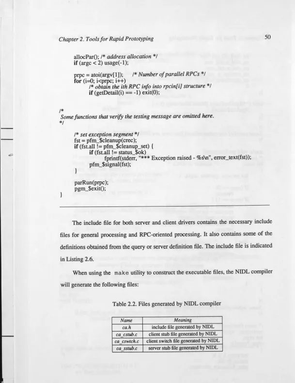
2.2. Files generated by NIDL compiler 50
I 2.3. Field type definition
67
-II 3.1. Controller commands 93
II
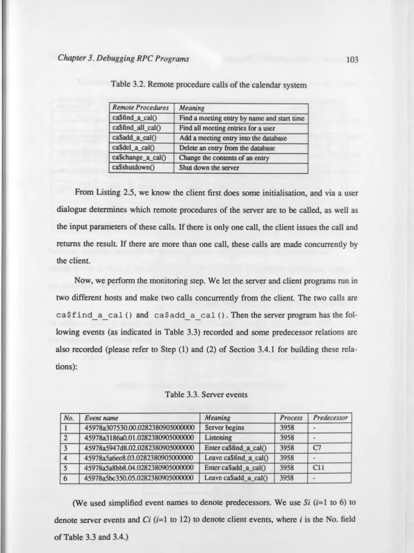
3.2. Remote procedure calls of the calendar system 103
c::,,
3.3. Server events 103
3.4. Client events 104
3.5. Remote predecessor/successor relations 104
3.6. Final predecessor/successor relations 105
4.1. Colours and their usage in Algorithm 4.1 114
xiii
-List of -Listings and Algorithms
Listing 2.1. Server definition file syntax 33
Listing 2.2. Server definition file for calendar server ca.def 41
Listing 2.3. NIDL file for calendar seiver ca.def 42
Listing 2.4. Seiver driver file for calendar seiver ca.def 43
Listing 2.5. Client driver file for calendar seiver ca.def 46 I
Listing 2.6. Include file for calendar seiver ca.def 51
Listing 2.7. Interface definition file syntax 55
58 I
Listing 2.8. Menu data structure I
Listing 2.9. Interface definition file example 59 ' I
Listing 2.10. Menu driver file 60 I
Listing 2.11. Menu include file 62 I
I
Listing 2.12. Database definition file syntax 66
Listing 2.13. Database definition file example 69
I
Listing 3.1. Event data structure 91
I
Listing 3.2. Event definition file syntax 96
Algorithm 4.1. 115
Algorithm 5.1. 146
Algorithm 5.2. 147
Algorithm 5.3. 148
Algorithm 5.4. 149
Algorithm 5.5. 150
Algorithm 5.6. 151
Algorithm 5.7. 158
-
~
Chapter 1
Introduction
1.1. Historical Notes
The strictly sequential computer model was proposed by von Neumann and his
contemporaries to avoid a large number of difficult problems intrinsic to parallel
com-putation. In this model, one instruction is processed at a time. The sequential model of
computation subsequently dominated programming for many years.
In the 1950's, computer designers began to depart from this strictly sequential
model of computing. For example, Input/Output controllers were introduced into
com-puters to work "concurrently" with the central processing unit (CPU). This relieved the
fast CPU from waiting on the slower Input/Output devices. In modern
multipro-grammed s;stems many separate jobs can be loaded and run simultaneously, with the
system relying on the services of several logically distinct but communicating processes
to deal with the stream of jobs. By connecting terminals to host computers, one can
access the host computer from distant locations. This can be viewed as the first
"geo-graphical" distribution of a computer system.
I
I
I
I
I
, I
1
-I
Chapter 1. Introduction 2
Then in the early 1970's,a few years after the emergence of minicomputers (which in some instances were designed as single-user computers for software development), the motivation for distributed systems became apparent. By connecting computers with each other, computer networks are created. Since then, especially during the 1980's, we have seen an explosion of the interest in and availability of distributed systems. We mention here three of the most important reasons for this growing interest:
1. Sequential machines have approached the fundamental limits of the computing power they can provide [Bodlaender87]. The cost of VLSI processor and memory components has fallen dramatically and is continuing to do so, and high-speed net-working technologies are now widely available at moderate cost. Further contri-butions to the speeding up of computer systems seem to be possible and economi-cal only if parallelisation of the hardware and of the programs is used. This leads to a distribution of hardware units, control units, and software.
2. Increasingly diverse application facilities are required by users [Coulouris88]. For example, users may want to perform network-based communication, complex information retrieval, and interactive graphics operations. All these operations involve many computing resources and various kinds of information located in different locations. The natural architecture for these applications involves the dis-tribution of facilities to different sites, connected by communication links. Each facility may include computing power, information, programs, Input/Output dev-ices, and other needed resources.
3. Our dependence on computing systems today is so great that computer failures may lead to life-threatening consequences and significant economic impact [Max-ion87]. Fault tolerance is now a required attribute of computing systems. One of the possible ways to achieve fault tolerance is to duplicate the hardware com-ponents in the system, such as processing units [Zhou90b]. In this way we not only achieve a speed up of the computer system, but we also may obtain a more reliable
..
Chapter 1. Introduction 3
computer system: when some components malfunction and others do not, the sys-tem as a whole may continue to work properly by letting the "good" components
also do the work of the "bad" ones.
The development of single-user workstations, file servers, and high-speed local networks during the 1980's is an important impetus for distributed system research and development. With a single-user workstation, a user can have dedicated processing power, enabling an application program to maintain an interactive dialogue with the user without interruption. Through the high-speed network, the user can access resources in file servers, which manage and store shared information and user files.
The earliest development of a workstation-based distributed system (single-user workstation&, servers, and high-speed local network) was at the Xerox Palo Alto Research Center in the period 1971-1980 [Coulouris88]. The first workstation developed was the Alto and came into general use in 1973 [Thacker81]. Then begin-ning from 1980, early stage commercial workstations, such as the Apollo Domain DNlOO, D:t-.i300 and DN600, Sun Microsystems Sun-1 and Sun-2, and Apple Macintosh II became available.
Since 1980, there has been a rapid expansion of the research and development of distributed systems. For example, the LOCUS [Popek85] system developed at the University of California, Los Angeles, the Network File System by Sun Microsystems, the Argus [Liskov83] integrated programming language and system, the Cambridge Distributed Computing System [Needham82], the Apollo Domain system [Leach83], the Amoeba system [Mullender85] at the Vrije (Free) University and CWI, Amsterdam, and the Mach distributed system [Mason87] developed at Carnegie-Mellon University. Three of t.l"..!se distributed systems, the Sun NFS, the Apollo Domain, and the LOCUS have been developed to commercial products .
I
I
I
I
I
'
-]
Chapter 1. Introduction 4
1.2. Distributed Systems Overview
For clarity we use the following terminology conventions. The term architecture will be used to describe hardware aspects while the terms model, structure and comput-ing will be used to describe software aspects. The term system will be used to describe the combination of hardware and software.
A common feature of all distributed systems is that there are multiple processes, processors or computers that communicate and cooperate with each other. LeLann [LeLann81] discussed the aims and objectives for distributed systems and notes some defining characteristics. We draw the distinction between a parallel system and a distri-buted system. In a parallel computer system many identical processors will work on the same problem simultaneously, the processors work synchronously, and the communica-tion delay time is not large compared with the computacommunica-tion time of a processor. The processors are connected in an "interconnection network". In a distributed computer system the processors (or computers) will work asynchronously, the processors may be of different types, and the communication delays may be large in comparison to the computation time of a processor. The processors are connected in a "computer net-work".
The implementation of distributed systems is constrained by the underlying hardware and basic communication software. In this dissertation we only consider sys-tems that are produced by combining a communication network (such as ethernet [Shoch83] or token ring [Bux83]) with conventional processors (computers). Alterna-tive architectures such as dataflow machines [Sharp85], systolic systems [Kung88] fall outside the scope of th~ dissertation.
loca-Chapter 1. Introduction 5
tions of the computer systems are large as in, for example, world-wide networks. For
LAN s, the scale is much smaller. The smaller distances facilitate different technologies
for faster information transfers between the sites involved. Typically the computer sys
-tems connected in a LAN are workstations and personal computers, within a short dis
-tance of each other. For example, all the nodes of a LAN may be located in the same
building or in several adjacent buildings.
Kirkp. trick [Kirkpatrick89] gives a more precise definition for a LAN. According
to his definition, a LAN is no longer a purely local matter. It can span as large as a geo
-graphical area as a continent, in which there are two or more LANs connected together,
but there is a single address space. Essentially, two characteristics are unique in LANs
and not in WANs. Firstly, all nodes in a LAN may listen to all information, while in a
WAN, not all nodes can listen to the information on the WAN. Secondly, a LAN has a
single address space at Layer 2 (data link layer) of the OSI ISO reference model
[Standard84] whereas a WAN has a single address space at Layer .3 (network layer).
Because of these characteristics, a LAN can send larger packets than a WAN. It
has small latency, lower error rate (lower noise), and higher bandwidth. Usually a LAN
is managed by a single economic entity.
Some authors define the consequences of distribution in terms of separation and
transparency ([Popek85], [Coulouris88]). The separation of components is an inherent
property of distributed systems. Separation allows the truly parallel execution of
pro-grams, the containment of component failures and the recovery from faults without
disruption of the whole system, and allows the incremental growth or contraction of the
system through the addition or subtraction of components. Because of separation,
tech-niques for communication and integration become necessary.
Transparency is defined as the concealment of separation from the user and the
application programmer. With the help of transparency, the programmer can perceive
I
Chapter 1. Introduction 6
Transparency is one of the major influences on the design of distributed system software.
1.3. Distributed Computing
Distributed comp11ting is concerned with the software aspects of distributed sys-tems. In terms of the ISO OSI reference model, it is about the application layer and presentation layer.
Many distributed systems m use and under development are based on
workstation/server model [Coulouris88]. In this model, each user is provided a
single-user computer, known as a workstation. Application programs are executed in the user's workstation. File servers store and manage shared data and other specialised dev-ice servers manage expensive devdev-ices such as laser printers, plotters and scanners. One possible extension to this model is to have different types of workstations, or even some multi-user computers connected in the network,
computer system [Notkin88].
resulting ma heterogeneous
1.3.1. Client/Server Model and Remote Procedure Calls
Most programs executing in the above distributed systems have the client/server
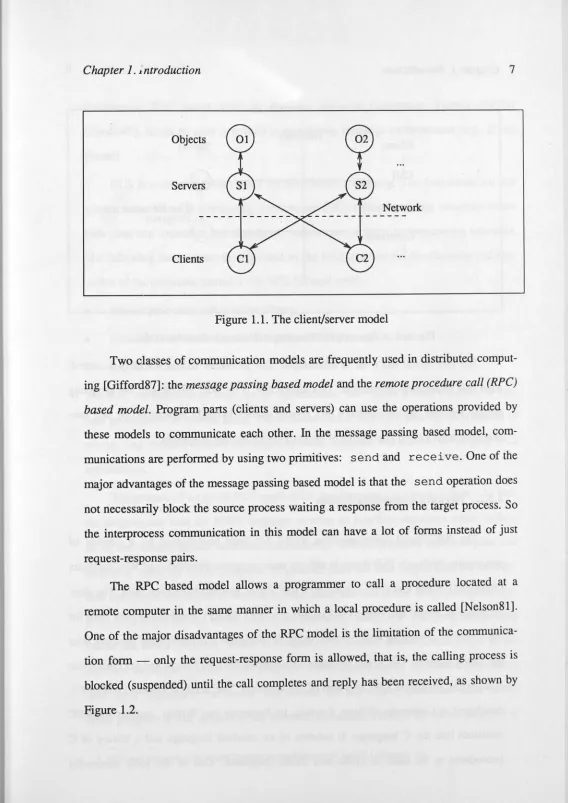
structure ([Svobodova85], [Leeuwen89]). The rationale for client/server model was described by Gentleman [Gentleman81]. In this model, server processes manage objects and client processes access these objects by using communication facilities provided by the system and servers. Servers are shared by many client processes. Figure 1.1 pictures this model. Here serv~r S 1 and server S
2 manage objects O 1 and O 2, respective! y. Client C 1 and client C 2 access these objects by using the remote operations provided by the servers. These servers and clients may reside on different hosts within the LAN.
!
Chapter 1. ~ntroduction 7
Objects
Servers
Network
[image:23.621.38.606.24.827.2]Clients
Figure 1.1. The client/server model
Two classes of communication models are frequently used in distributed comput-ing [Gifford87]: the message passcomput-ing based model and the remote procedure call (RPC) based model. Program parts (clients and servers) can use the operations provided by these models to communicate each other. In the message passing based model, com-munications are performed by using two primitives: send and receive. One of the major advantages of the message passing based model is that the send operation does not necessarily block the source process waiting a response from the target process. So the interprocess communication in this model can have a lot of forms instead of just request-response pairs.
11
I ...
Chapter 1. Introduction
Client
clu
SuspendContinue
!
Network
Server
[image:24.663.2.618.21.851.2]The Remote Program
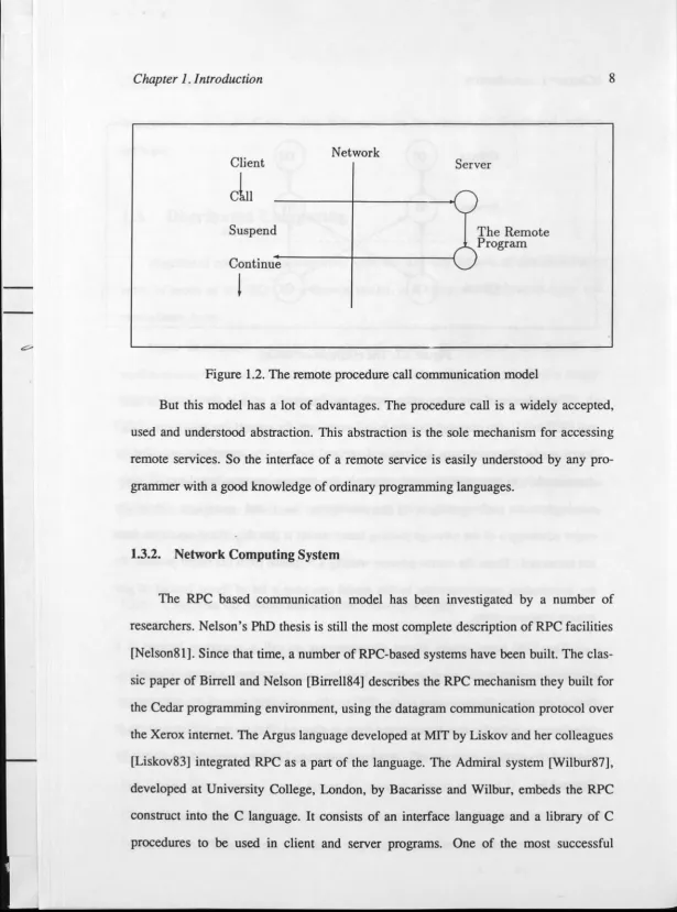
Figure 1.2. The remote procedure call communication model
8
But this model has a lot of advantages. The procedure call is a widely accepted, used and understood abstraction. This abstraction is the sole mechanism for accessing remote services. So the interface of a remote service is easily understood by any pro-grammer with a good knowledge of ordinary programming languages.
1.3.2. Network Computing System
The RPC based communication model has been investigated by a number of researchers. Nelson's PhD thesis is still the most complete description of RPC facilities [N elson81]. Since that time, a number of RPC-based systems have been built. The clas-sic paper of Birrell and Nelson [Birrell84] describes the RPC mechanism they built for the Cedar programming environment, using the datagram communication protocol over the Xerox internet. The Argus language developed at MIT by Liskov and her colleagues [Liskov83] integrated RPC as a part of the language. The Admiral system [Wilbur87], developed at University College, London, by Bacarisse and Wilbur, embeds the RPC construct into the C language. It consists of an interface language and a library of C procedures to be used in client and server programs. One of the most successful
~.
Chapter 1. Introduction 9
commerciru RPC based tools is Apollo's Network Computing System (NCS)t
[Apollo87]. It can be used in several programming language environments (e.g., C and Pascal).
NCS is a set of software tools for distributed computing. The foundation for this
system is the Network Computing Architecture (NCA) which supports situations where
both data and execution are distributed across one or more heterogeneous networks.
The following components are provided by the NCS to assist the development and
exe-cution of the programs related to the NCS [ZhouRep88]:
•
remote procedure call runtime library,• network Interface Definition Language (NIDL) compiler, and
• location broker.
The RPC runtime library provides the system calls that enable a local program to
exe-cute procedures on remote hosts. The location broker then provides the information of
remote (and local, of course) services. The NIDL compiler is a tool for developing NCS
applications.
The process of a typical NCS application development may be as follows. At first,
the programmer uses the NIDL language to write an interface definition which defines
all of the remote service interfaces (procedures). The programmer then compiles this
definition using the NIDL compiler. In general, there are four output files for an inter
-face definition, where two of them are client stubs, one is a server stub, and the last one
is an include file for the use of both client and server programs. The programmer then
builds the server program, which implements the remote interfaces described in the
interface definition, and the client program, which makes use of the remote procedures
(and other application functions). The format for the remote procedure calls in the
client program is that defined in the interface definition. Finally, the server program is
t
NCS and Network Computing System are trademarks of Apollo Computer Inc.'
1
I - ~
Chapter 1. Introduction 10
linked with the server stub and the client program is linked with the client stubs. Now the server program cru. run on the remote host and the client program running on the local host can execute the remote procedures in the same way as it requests local pro-cedures.
One can notice that we did not mention the location broker above. A small and specific application needs to have no recourse to the location broker because the client program knows where the remote services are located. The location broker is very use-ful in general, however. Usually, a server program must register all of its services with the location broker. The client program can then find the service through the location broker. After the client finds the location of the service, it then calls the service directly. This is called unbound (or allocated) calling. We will use this as the standard calling semantics. Of course, NCS also supports other calling semantics, such as bound-to-host and fully bound calls [Apollo87].
There are two kinds of location brokers, called the Global Location Broker (GLB) and the Local Location Broker (LLB), respectively. The LLB provides the services information of its local host, and the GLB provides the services information of the whole network. When the difference between these location brokers is not important, we will use the term location broker (LB) to specify them. There are some system calls provided by the NCS to manage the location brokers. Because there may be many ser-vices registered in a location broker, a unique naming facility called Universal Unique Identifier (UUID) is employed. Each service has to be assigned a UUID before it is registered to the LB. These UUIDs are used by NCS to distinguish one service from another. The NCS provides system calls to support this function.
A distributed program in NCS can be functionally divided into two parts: the server part and the client part. Each part can be located on any host in the network. Usually, a server part manages an object, and a client part accesses the object by using the remote procedures provided by the server. A RPC-oriented program (in short, a
Chapter I. Introduction 11
RPC program) may consist of several servers and clients, and all these parts of the
pro-gram work :ogether concurrently on the propro-grammer's task. A server or client can fork
to several processes if necessary.
1.3.3. Distributed Application Model
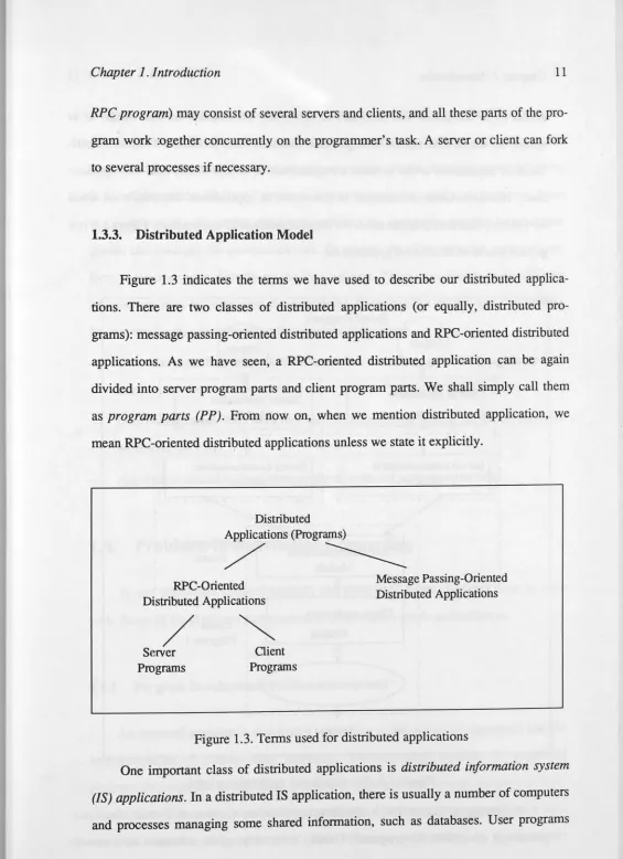
Figure 1.3 indicates the terms we have used to describe our distributed
applica-tions. There are two classes of distributed applications (or equally, distributed
pro-grams): message passing-oriented distributed applications and RPC-oriented distributed
applications. As we have seen, a RPC-oriented distributed application can be again
divided into"server program parts and client program parts. We shall simply call them
as program parts (PP). From now on, when we mention distributed application, we
mean RPC-oriented distributed applications unless we state it explicitly.
Distributed Applications (Programs)
/
---RPC-Oriented Distributed Applications
/
Server Programs
Client Programs
[image:27.614.35.600.28.806.2]Message Passing-Oriented Distributed Applications
Figure 1.3. Terms used for distributed applications
One important class of distributed applications is distributed information system
(JS) applications. In a distributed IS application, there is usually a number of computers
and processes managing some shared information, such as databases. User programs
..
I
I
I I
I
l
I I
Chapter 1. Introduction 12
access these computers and processes to obtain the information the user needs, or to update the stored information through these computers and processes. Time in a distri-buted IS application is not as strict a requirement as in distributed real-time applica-tions. This dissertation is interested in distributed IS applicaapplica-tions. From now on, when
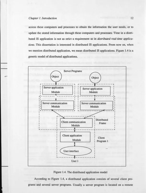
we mention distributed application, we mean distributed IS applications. Figure 1.4 is a generic model of distributed applications.
Q
Server Programsr---~---,
Server application Module
Server application Module
I I
r--- "'---' ---
-
---',
+
:
IServer communication Module
. . - - ~ ~ ~ - - - - ' ~ ~ ~ ~ ~ - - , I I Server communication 1 :
I
Module , :
I
,L---
~~~~~~~----:o~_-_-_-_-_~J,
',
, Oient communication
I
, Module
--,
: Distributed Frame
I I I I
L---' --- __________ l __________ J
I
I I
Client application Module
L---
---
-
J
User 1
[image:28.663.2.614.21.827.2]Client Program 1
Figure 1.4. The distributed application model
Chapter 1. Introduction 13
computer and a client program is located on the user's (local) computer. A client
pro-gram interfaces with the user, manages the local application process, and performs the
communication between the client program and other related (remote) server programs
(e.g., talking to the GLB and servers). A server program usually manages an object
(e.g., one part of a distributed database), performs the operations required by other
pro-grams, and manages the communications. Of course, the client program may also per
-form some operations directly on the local objects. This is not shown in the diagram
because we want to emphasise the distributed characteristics of the application here.
So, we can divide a distributed application into three parts:
User interface. This deals with the interactions between the client program and the
user.
Distributed frame. This performs the communications among all the co-operative
parts <.,ver the LAN.
Application modules. They manage the objects and perform operations.
1.4. Problems in Distributed Computing
To use distributed systems correctly and efficiently, many problems must be dealt
with. Some of the problems addressed in the dissertation are described below.
1.4.1. Pre gram Development Problems
An essential problem in distributed computing is the design of algorithms and the
implementation of corresponding programs. The equivalent problem for sequential
program development is nowadays reasonably managed and a large number of
tech-niques exist. Due to the fact that many parts of a distributed program will work
•
II
I
Chapter 1. Introduction 14
nondeterministic way, distributed programs seem more difficult to understand than sequential programs. Consequently, distributed programs are more difficult to design and program. We mention the following interesting aspects.
Distributed Programr.ting
Programming a distributed program is much more difficult than programming a sequential program because the former involves communication and cooperation among processes. For instance, in programming RPC-based programs, one has to write server and client communication stubs, modules of RPC procedures, server programs, client programs, user interfaces, and application modules. Although some facilities are provided to ease the burden of distributed programming (for example, NCS provides a NIDL compiler (see Section 1.3.2) which can produce server and client communication stubs from a specification file), the programming process for distributed programs is still more complex than for sequential programs.
Suppose we are going to build a calendar database management system [ZhouRep89] (see Section 2.2.2 and Appendix A for details) by using NCS. We may use the following steps to implement the system:
• Define the program structure and remote procedure interfaces. Usually we use a server program to manage the calendar database, and allow several client pro-grams to access the database through the remote procedures exported by the server. Then, the server program must have the ability to maintain the database operations, and the client program must have the ability to interact with users. After the definition of the program structure, the interfaces for all remote pro-cedures that the server is going to export can be defined. This is actually the inter-face between the server and the client programs based on the programmer's point of view.
-Chapter 1. Introduction 15
• Generating stub modules. The definition file is written in the NIDL language. After using NIDL compiler, the server and client stub modules will be generated. Now, the client program can view the client stub module as the "local version" of the server program, and the server program can view the server stub module as the
"local version" of the client program. These stub modules perform most of the lower level communications between server and client.
• Write server program modules which perform the real work of the remote pro-cedures. For example, if a remote procedure corresponds to "insert a new record into the database," the real procedure which does the insertion of the record must be built as a part of the server program.
• Write client program modules which make use of the remote procedures and interact with users.
• Combine server program modules together to form the server program.
•
Combine client program modules together to form the client program .The RPC program is then ready to execute. Several problems may arise during the development process.
1. It takes a long time before an executable version of the system is ready for testing because the programmer has to write all those modules before they can be com-bined and tested. During this time, the user requirement may change. If the modules are written by several programmers simultaneously, the interfaces between them are an intrinsic problem for group development.
2. Because a distributed program is relatively complex in the sense that cooperating modu"i.~s and programs are involved, it is very difficult to manage the correctness of all these parts. In the above we mentioned the process involved in the creation of one server and its client programs. If there are several servers in the system (which is usually the case), the programmer has to do the same thing for each
I
I
I I I
I
!
l
I'
I
-Chapter 1. Introduction 16
server and its client programs. If a client program is going to use several servers'
remote procedures simultaneously (which is also typical in distributed
program-ming), the situation becomes even worse. The memory of human beings is limited.
When there are too many things to be remembered during the development
pro-cess, it is very easy for programmers to make mistakes. When there are errors in
the program, it is very difficult to find them because of the complexity of the
sys-tem.
3. It is very difficult to accommodate module changes during the development
pro-cess. For example, if one of the remote procedure interfaces is changed, the
grammer has to change all the program modules involved such as the server
pro-gram modules which export the remote procedure and the client modules which
use the remote procedure. Of course module changes are intrinsic to program
development processes.
Our solution to these problems involves a set of rapid prototyping tools for
distri-buted program development. By using these tools, one can quickly build an executable
version of the system. The program modules generated by these tools are relatively
correct because these tools are tested. Also these tools allow changes in interface and
modules to be accommodated. For example, if a remote procedure interface is changed,
the prototyping tools will automatically change all the appropriate modules in the new
prototype.
Distributed Program Debugging
Debugging is a process of isolating, diagnosing and correcting program errors
[Fairley85]. For large systems this is one of the most costly phases in the program
development process [McDowe1189]. Debugging a distributed program is usually much
more difficult than debugging a sequential program. The concurrency and
communica-tion among the concurrent parts make debugging of distributed programs difficult
..
Chapter 1. Introduction 17
[Miller86]. We list the following typical difficulties:
• Because several parts (programs or processes) may execute on different hosts
simultaneously, some events will occur at the same time. But in general there is no
global timing base that can be provided for all the hosts of a distributed system, so
we cannot completely order the events in a distributed program nor accurately
measure when these events occur. This is in direct contrast to the situation with the
debugging of a sequential program.
• Because of the finite but nondeterministic time needed for communication
between hosts, there is no way to obtain a snapshot of a distributed program's
glo-bal state. Nor is it possible to have instantaneous cbnge of control for all parts of
a computation on different hosts. That means that methods such as breakpoint and
stepping are not as effective as in sequential debugging.
• Because of the processes in a distributed program work concurrently, and the time
needed for their activities is nondeterministic, it is almost impossible to re-do an
execution to obtain the same behaviour. This breaks one of the fundamental
assumptions of the sequential debugging [Garcia85].
• Because of the communication time between hosts is much longer than the
com-putation time within a host, an error condition in a host may affect many processes
before it is detected or noticed by the programmer. This complicates the
determi-nation of where the error really occurred. Although this error propagation effect
also exists in sequential debugging, the affected area can be much smaller than in
distributed debugging because of the shorter latency time.
It is evident that the ability to trace communication events and concurrent events
(as well as other events) that occur during a distributed program's execution is
funda-mental to any debugging tool. Most existing studies of distributed debugging and
moni-toring are based on the message passing model. As the RPC model become more and
I
I - ~ .,,
Chapter 1. Introduction 18
Our solution to this is a RPC-oriented debugger which records all interesting events of a
distributed program into an appropriate database. A partial ordering among events is
then built. This ordering relation can be used to trace and replay the program's
execu-tion. The debugger and its database is distributed. It can monitor several distributed
programs simultaneously.
Performance Evaluation Problems
We have mentioned the construction and debugging of distributed programs. After
the distributed program is built, we may want to know how well it works. This involves
the performance evaluation of distributed programs.
One of the important performance metrics for a distributed program is the
expected execution time. Most existing evaluation methods use queueing theory to
analyse the expected execution time. But this time corresponds to the system's
viewpoint and averages over all possible jobs. In the other hand, a user is often
interested in the execution time of his own job, which is a quite different viewpoint
[Qin89].
We have developed a model for evaluating the execution time of a particular RPC
program. For simple programs we can derive explicit solutions. For complex programs,
a nondeterministic algorithm as well as the lower and upper bounds of the execution
time are developed.
1.4.2. Management Problems
A distributed application program consists of many concurrent processes, and the
purpose of the program is to have all these concurrent parts work together to achieve a
common goal. Therefore the management of the cooperation among these concurrent
•
Chapter 1. Introduction 19
parts are critical. We mention some of the interesting problems which arise with the management of a distributed program.
l. Resource sharing. Processes and program parts may want to use the same resources at the same moment. Therefore facilities must be dedicated to the fair and efficient allocation or occupancy of the resources, for instance, to avoid deadlock and starvation, and to maintain mutual exclusion.
2. Fault tolerant computing. For many problems in distributed computing one may want to have solutions that still behave correctly if one or a small number of processors/links/processes fail.
3. Atomic qctions. In some distributed applications, one may want to keep a group of operations atomic. That is, the effect of these operations is all-or-nothing. Because the involved operations may spread to the whole LAN, this task is difficult.
4. Accommodation of heterogeneity. In a LAN there can be several types of comput-ers. How these computers talk to each other is very important. But unfortunately, almost all existing RPC tools provide a closed environment. For example, a NCS/RPC can only talk to NCS/RPCs [Notkin88]. This brings many difficulties to the programming of heterogeneous computer systems. So interfaces between dif-ferent RPC tools are needed [Zhou90a].
1.4.3. Other Problems
The above list is only a subset of the problems in distributed computing, and other important problems exist. These include, load balance within a LAN, "global" state and ordering, communication protocols, the mapping of problems onto a known distributed
Chapter 1. Introduction 20
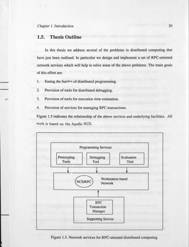
1.5. Thesis Outline
In this thesis we address several of the problems in distributed computing that
have just been outlined. In particular we design and implement a set of RPC-oriented
network services which will help to solve some of the above problems. The main goals
of this effort are:
1. Easing the burti,,.11 of distributed programming.
2. Provision of tools for distributed debugging.
3. Provision of tools for execution time estimation.
4. Provision of services for managing RPC transactions.
Figure 1.5 indicates the relationship of the above services and underlying facilities. All
work is based on the Apollo NCS.
Programming Setvices
Prototyping Debugging Evaluation
Tools Tool Tool
i
t
t
8
Workstation-basedNetwork
i
RPC Transaction
Manager
[image:36.670.11.627.17.822.2]Supporting Setvice
Chapter 1. Introduction 21
The contents of the following chapters are:
• Chapter 2 describes a set of prototyping tools which can generate RPC program prototypes from user specified description files. This approach frees programmers
from many of the details of programming, such as the establishment of
communi-cation during system initialisation and implementation of the user interface
([Zhou90c], [Zhou90d], [Zhou90f]). At first existing software development
methods are described and the prototyping model for distributed information
sys-tem applications is presented. The design and implementation of the prototyping
system are then described together with application examples from the distributed
calendar system.
• Chapter 3 presents a distributed debugger. It can debug and monitor a distributed
program system ([Zhou90d], [Zhou90g], [Zhou90h]). It first reviews the related
works and then gives several definitions that are basic for later discussion. The
structure of the debugger is then described and the method of trace analysis is
presented.
• Chapter 4 describes a technique for the estimation of the execution time of
RPC-oriented programs ([Zhou89], [Zhou90e]). After introducing the RPC program
model, a nondeterministic algorithm for calculating the execution time of a
gen-eral RPC program is presented. Although it is impossible to obtain the explicit
solution for a general RPC program at this moment, an explicit solution for some
special cases is presented. Then, lower and upper bounds for the general model are
derived. Applications of the theory are also presented.
• Chapter 5 gives the description of a RPC transaction manager which ensures the
transaction characteristic for a group of RPC operations [ZhouRep90b]. After a
survey on the existing work, we present a RPC model which is suitable for our
dis-cussion. Based on this model, a RPC manager is designed to manage a transaction
Ill
1
Chapter I. Introduction 22
By extending the RPC model, a transaction manager is designed for managing several RPC c~lls executed in parallel. Properties of the transaction manager are also described.
! Finally, Chapter 6 provides a summery of the thesis.
I
The best way to describe the application of the environment is through examples. I use a moderate size distributed application as the example. It is a distributed calendar
-
system and was developed during a working trip to Apollo Computer Inc. in MA, USA.-
To avoid describing its structure at several places in the dissertation, a description ofc;;,- the system is provided as an appendix.
llil
Chapter 2. Tools for Rapid Prototyping 23
Chapter 2
Tools for Rapid Prototyping
2.1. Rapid Prototyping and its Context
2.1.1. The Life-Cycle Model
For the past twenty years or so, software system development has been based on the software life-cycle model (or, waterfall model) [Boehm76]. This model essentially advocates that software projects should consist of a number of distinct phases [Boar84].
These are: specification, design, implementation, testing, operation and maintenance. This model has been modified by a lot of researchers since its inception. But the central idea remains unchanged, that is, all variations keep the linear structure, and each phase begins only when the previous phase has been completed.
Several assumptions underly the life-cycle model ([Agresti86], [Boar84]):
(1). Computers are an expensive resource, and their access should be preceded by careful planning so that the time on computers would be used effectively.
pro-l
.I -
-Chapter 2. Tools for Rapid Prototyping 24
duced prior to design and implementation.
(3). Successful software was developed by successively achieving subgoals at each
phase of the waterfall.
The life-cycle model works very well when the application is both well understood
and supported by previous experience, but in general, it has many deficiencies which
are too serious to be ignored [Hekmatpour88]. The reason is that some assumptions
made by life-cycle model are no longer true. We list the following deficiencies.
(1). The computers are much cheaper than 20 years ago and there are many program-ming tools available today. The access to computers and software are no longer
limited to people with specialised skills. The relative cost effectiveness of
com-puter hardware technology has increased by a factor of 10,000 since 1970
[Musa83]. A wide array of software development tools are being used for every
phase in the life-cycle model. Of greater significance, some current tools and
environments logically span several conventional phases, thereby challenging the
usefulness of the life-cycle's partitioning into phases [Agresti86].
(2). It is impossible to rigorously specify all requirements of a distributed IS
applica-tion. Many authors have pointed out that a complete, concise and consistent
specification of a proposed system is impossible ([Swartout82], [McCracken81],
[Shaw85], [Parnas86], [Agresti86], [Hekmatpour88]). The main reason is that, as
human beings, people need to see examples and have practical experience before
they are able to make judgements about the suitability of a proposed system and to recommend revisions. Even if a fine and valiant effort is made of specification, the
initial contact with the solution changes the individual's perception of what they
want.
(3). It is impossible to clearly divide and therefore achieve each subgoal of the
life-cycle model. For example, one cannot state a problem without some rudimentary
notion of what the solution should be [Agresti86]. That is, to separate the "what"
..
Chapter 2. Tools for Rapid Prototyping 25
of specification from the "how" of design is almost impossible [Swartout82]. Actu -ally, every specification is an implementation of some other higher level specification. Thus simply by shifting our focus to an earlier portion of the development, part of the specification becomes part of the implementation. The other thing is that requirements are often a fuzzy thing in the user's mind. So, the design and implementation according to these fuzzy requirements are often unworkable and need revision. In this case, when applying the life-cycle iliodel to the development of distributed IS application, all phases of the life-cycle often interact instead of falling into a linear structure, and hence the development stra-tegy fails.
(4). In the life-cycle model, the user may have to wait a long time before actually hav-ing a system available to him or her, because of the successive achievement of subgoals. But during this time, the user requirements as well as the user environ -ment may change considerably. This may cause frustration. Blum [Blum82] described this graphically: "Development is like talking to a distant star; by the time you receive the answer, you may have forgotten the question."
The importance of these observations is that the life-cycle model reflects the time period in which it evolved. Dramatic changes since then in the environment of the software process are promoting a reassessment of the model, and new development models are needed to fit the evolved technology and changed application domains.
2.1.2. Computer-Aided Rapid Prototyping
Computer-aided rapid prototyping has been suggested as an alternative scheme to
l
11
I
-Chapter 2. Tools for Rapid Prototyping
26
programs. When the proposed distributed IS application is too complex; when the user interface is an important part of the system; when the requirements cannot be com-pletely specified at the beginning; or when there are too many uncertainties about the proposed system, rapid prototyping is a, suitable model for development.
•
At the least, rapid prototyping is suitable in the following aspects.
To clean up ambiguities in the specification of a distributed IS application. When developers and users look into the system prototype together, they can find where the misunderstandings are between them and can address them.
• To make the user interface more friendly to users. When creating a user interface, developers usually impose their own judgement. That is, many features of the sys-tern are in the developer's mind-set and they may not specify or explain those features in the user interface. An expert cannot think as a computer layman. So the user interface created by a computer expert is usually not suitable to users. By using the system prototype, both the expert and the user can discuss this together. • To help users specify their wishes. Simply working through specification
docu-ments, users may not be able to specify their wishes. By working with the system prototype, they may be able to do so.
• To cope with changes during the development of the system. Because the proto-types are generated by tools, it is easy to cope with design changes.
Several approaches to rapid prototyping exist [Hekmatpour88]. In throw-it-away prototyping, the prototype system is used for a limited period, and is usually used for requirements analysis and specification. After that, it is thrown away. The rapid development of the prototype is the greatest need, while the efficiency of the prototype is of little importance. A second approach is called evolutionary prototyping. Here a system grows and evolves gradually. At first, only those parts of the system that are well understood are developed, and the prototype then evolves as the understanding of the whole system becomes clearer during the use of the first prototype. This is very
I-...
1-Chapter 2. Tools for Rapid Prototyping 27
suitable for graduately introducing a new system into an organisation and for coping with the changes that take place within the organisation as a result of using the system. This method is the most attractive model for IS applications. It is the prototyping method used in this chapter.
In all cases, a prototype must be a "working model" of the proposed IS applica-tion. The challenge is then to develop the related software tools that will support the prototyping process. In the next section, we present several tools that help the develop-ment of distributed IS application prototypes.
2.2. Structure of the Prototyping Tools
2.2.1. The Prototyping Model
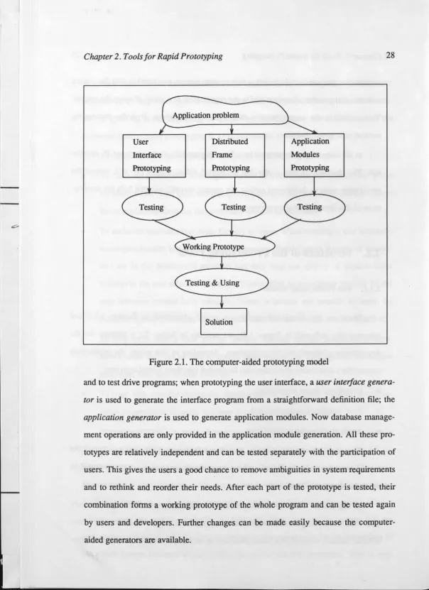
Based on the distributed application model (described in Section 1.3.3 and schematically indicated in Figure 1.4), we indicate in Figure 2.1 a strategy for the development of distributed IS applications. According to this model, the prototyping process for a distributed application can be divided into three related activities:
• Distributedframe prototyping,
• User interface prototyping, and
• Application modules prototyping.
One of the prerequisities of this computer-aided prototyping model is that all the related tools are available. When user requirements change, a new prototype should be ready for testing in a short time.
Chapter 2. Tools for Rapid Prototyping
User Interface Prototyping
Application problem
Distributed Frame Prototyping
Solution
[image:44.660.4.609.18.849.2]Application Modules Prototyping
Figure 2.1. The computer-aided prototyping model
28
and to test drive programs; when prototyping the user interface, a user inteiface
genera-tor is used to generate the interface program from a straightforward definition file; the
application generator is used to generate application modules. Now database manage-ment operations are only provided in the application module generation. All these
pro-totypes are relatively independent and can be tested separately with the participation of users. This gives the users a good chance to remove ambiguities in system requirements and to rethink and reorder their needs. After each part of the prototype is tested, their
Chapter 2. Tools for Rapid Prototyping
29
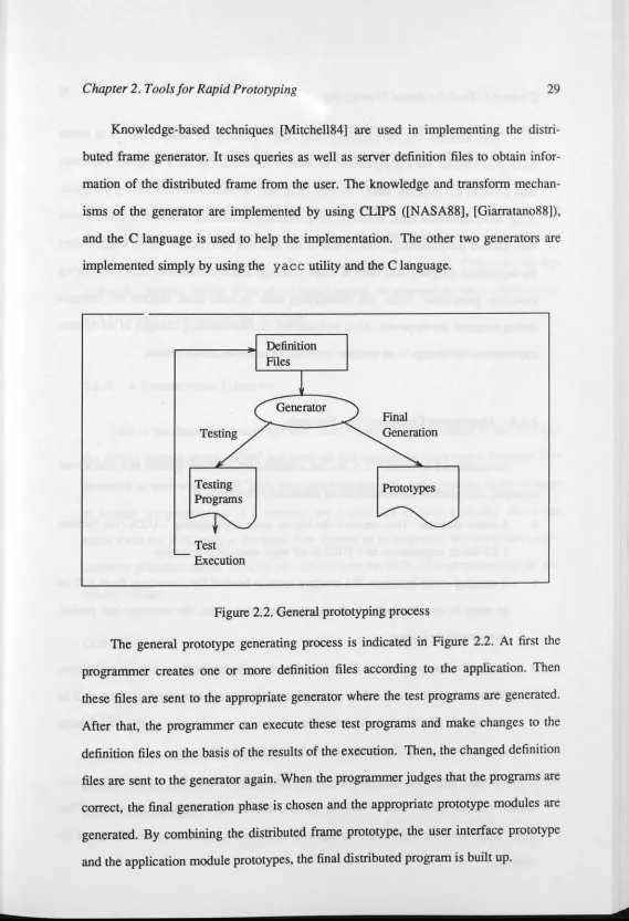
Knowledge-based techniques [Mitchell84] are used in implementing the distri
-buted frame generator. It uses queries as well as server definition files to obtain
infor-mation of the distributed frame from the user. The knowledge and transform
mechan-isms of the generator are implemented by using CLIPS ([NASA88], [Giarratano88]),
and the C language is used to help the implementation. The other two generators are
implemented simply by using the yacc utility and the C language.
Testing
Programs
Test Execution
Definition Files
Generator
[image:45.625.44.613.19.852.2]Prototypes
Figure 2.2. General prototyping process
The general prototype generating process is indicated in Figure 2.2. At first the
programmer creates one or more definition files according to the application. Then
these files are sent to the appropriate generator where the test programs are generated.
After that, the programmer can execute these test programs and make changes to the
definition files on the basis of the results of the execution. Then, the changed definition
files are sent to the generator again. When the programmer judges that the programs are
correct, the final generation phase is chosen and the appropriate prototype modules are
generated. By combining the distributed frame prototype, the user interface prototype
!
Ii
I
Chapter 2. Tools for Rapid Prototyping 30
Three benefits can be obtained from these prototyping tools. First, it is much
quicker and easier for a programmer to write a definition file for a program generator
than to write the program itself. Second, it is easy to make mistakes during
program-ming. With definition files, however, the possibility of making mistakes is smaller than
with general programming. This is due to the fact that a definition file is simpler than
the equivalent program, and there is some syntactic and even semantic checking during
prototype generation. Third, the prototyping tools provide more support for changes during program development. As is well known, accommodating changes to the system
requirement and design is an intrinsic property of software development.
2.2.2. Distributed Calendar: The Example
As mentioned in Section 1.5, we use a distributed calendar system as a non-trivial
example. The system has three kinds of databases [ZhouRep89]:
• A name database. This contains the names and corresponding UUIDs (see Section
1.3.2 for an explanation of UUID) of all legal users of the system.
• A meeting-room database. If a meeting room is booked for a meeting, there will be an entry. in this database which contains the room name, the meeting time period,
and other information.
• A set of calendar database files. There is one calendar database file for each group
of users (e.g. all users within a department). If a user has a meeting, there will be an entry in his calendar database file which contains the user name, the meeting
time interval, a lot of participants, and other information.
For each database, there is one server which maintains it. We call these a register
server, a room server, and a calendar server, respectively. All these servers run
"for-ever" in the network. Figure A-1 in appendix A describes the structure and usage of the system.