DECISION FEEDBACK AIDED BAYESIAN TURBO SPACE-TIME EQUALIZER FOR PARALLEL
INTERFERENCE CANCELLATION IN SDMA SYSTEMS
A. Wolfgang, S. Chen, L. Hanzo
School of ECS Univ. of Southampton, SO17 1BJ, UK.
Tel: +44-23-80-593 125, Fax: +44-23-80-594 508
{
aw03r,sqc,lh
}
@ecs.soton.ac.uk
http://www-mobile.ecs.soton.ac.uk
ABSTRACT
A novel Bayesian Decision-Feedback aided turbo Space-Time
Equalizer (DF-STE) combined with a Parallel Interference
Cancellation (PIC) scheme and designed for multiple antenna
assisted receivers is introduced. The proposed receiver
struc-ture allows the employment of a non-linear Bayesian turbo
DF-STE operating at a moderate computational cost, which
outperforms the linear turbo detector benchmarker based on
the Minimum Mean-Squared Error (MMSE) criterion, even
if the latter aims for jointly detecting all transmitters’ signals.
I. INTRODUCTION
Turbo equalization has been the subject of intensive research
efforts and many of the algorithms originally developed for
single-user equalization [1] [2] have been extended to multi-user
models either in the form of turbo Multi-User Detectors (MUDs)
designed for Code Division Multiple Access (CDMA) systems [3]
or to Space Division Multiple Access (SDMA) receivers [4].
Their extension from single-user to multi-user equalization
im-posed an increased computational complexity. Therefore the joint
detection of signals arriving from multiple transmitters has mostly
been considered in the context of moderate-complexity linear
de-tection techniques, such as for example Minimum Mean Squared
Error (MMSE) filtering. Employing joint Maximum Likelihood
(ML) rather than MMSE detection would be excessively complex,
since the receiver complexity increases exponentially both with
the number of transmitters that have to be detected and with the
Channel Impulse Response (CIR) length.
A different set of detection techniques, which are also
rem-iniscent of the linear turbo detectors designed for detecting
the signals arriving from multiple transmitters, is constituted
by the family of so-called Interference Cancellation (IC) based
schemes [3]. These IC schemes may be implemented either in
a Parallel (PIC) or a Successive (SIC) fashion. The PIC turbo
detector proposed in this paper enables us to combine the linear
cancellation of the Multiple Access Interference (MAI) and the
non-linear or classification based removal of the channel-induced
Inter Symbol Interference (ISI). The combination of PIC and
non-linear classification-based channel equalization is capable of
outperforming the MMSE based joint detection of all users at the
cost of a moderate complexity increase, as it will be shown in
this contribution.
The remainder of the paper is organized as follows. In
Sec-tion II we will present our system model, which is used in
Section III to briefly introduce two different joint detection
strategies. In Section IV we will further develop our system
model for the sake of deriving a PIC based non-linear detector.
The achievable performance of the different schemes is further
discussed in the light of the complexity imposed in Sections V
and VI, respectively. In Section VII we offer our conclusions.
II. SYSTEM MODEL
The system considered consists of
Q
number of Binary Phase
Shift Keying (BPSK) modulated sources and a Base Station (BS)
receiver, which is assumed to employ
L
number of antennas. The
mobile stations’ (MS) transmitters encode the source bits
employ-ing a convolutional encoder and interleave the resultant coded
bits with the aid of a random interleaver. The channel coded and
interleaved bits are then BPSK modulated and transmitted to the
BS over a frequency selective fading channel having a
symbol-spaced CIR.
Given the coded and modulated symbol
s
(
t
)
, which is
associ-ated with the
q
thtransmitter, the output signal of the
l
thantenna
element of the BS receiver at time instant
t
can be written as
x
l(
t
) =
Q−1q=1 K−1
k=0
h
lq,ks
q(
t
−
k
) +
η
(
t
)
,
(1)
where
h
lq,kis the complex-valued channel gain of the
k
thmulti-path component describing the channel between the
q
thMS and the
l
thBS receiver antenna. Furthermore,
K
is the
number of symbol-spaced multi-path components and
η
(
t
)
is the
complex-valued Additive White Gaussian Noise (AWGN) having
a variance of
E
|η
l(
t
)
|
2= 2
σ
2.
Assuming that all MSs transmit at an identical power, the
resultant
EbN0
value for the BPSK modulated source
q
and
code-rate
R
is given as
E
bN
0=
1
R
L l=1 K−1 k=0E
|h
lq,k|
22
σ
2L
.
(2)
Each of the BS receiver’s antenna elements in Equation (1) is
followed by a tapped delay line of length
m
, which is also
referred to as the feed-forward section of the STE. In vectorial
notation, the channel’s output can be expressed by the
super-vector
x
(
t
) =
x
(
t
)
T, . . . ,
x
(
t
−
m
+ 1)
TT, where
x
(
t
)
is a
column vector hosting the
L
number of antenna-element output
signals
x
l(
t
)
given in Equation (1). The relation between the
signal transmitted by the
Q
MSs and the channel output for
channel tap
k
is described by a
(
L
×
Q
)
-dimensional matrix
H
k, where the
(
lq
)
thelement of the matrix is given by
h
lq,k.
The super-matrix
H
representing the total system can then be
obtained by concatenating the (
L
×Q
)-dimensional matrices
H
k,
yielding:
H
=
H
k· · ·
H
k−m+10
· · ·
0
. .
.
. .
.
0
· · ·
0
H
k· · ·
H
k−m+1
.
Crown Copyright 2005
The channel output vector
x
(
t
)
can now be expressed as
x
(
t
)
=
H
s
(
t
)
T, . . . ,
s
(
t
−
m
+ 1)
TT+
η
1(
t
)
T, . . . ,
η
L(
t
)
TT=
Hs
(
t
) +
η
(
t
)
=
x
(
t
) +
η
(
t
)
,
(3)
where
s
(
t
) = [
s
1(
t
)
, . . . , s
Q(
t
)]
Tis a column vector
con-taining the symbols transmitted by the
Q
MSs and
η
l(
t
) =
[
η
1(
t
)
, . . . η
l(
t
−
m
+ 1)]
T.
III. JOINT DETECTION
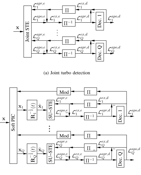
The turbo detection scheme used is depicted in Figure 1(a).
In the context of turbo detection the information generated by
the different receiver components is exchanged between them in
the form of Log Likelihood Ratios (LLRs), which are defined as
L
(
s
q(
t
)
|
x
(
t
)) =
P(sP(sqq(t)=+1|x(t))(t)=−1|x(t)). In our further discussion, the
time index
t
is neglected for notational simplicity and we define
L
q=
L
(
s
q(
t
)
|
x
(
t
))
. Considering now the joint detection of all
users, the detector first performs a soft detection of the received
signal vector
x
(
t
)
and returns the aposteriori LLR of the
inter-leaved channel coded bits
L
apo,eq, where the superscript
erepre-sents the STE. The apriori LLR denoted by
L
apr,eqis removed
from the aposteriori LLR resulting in the extrinsic information
L
ex,eq
which is passed by the deinterleavers denoted by
Π
in
Figure 1(a) to the channel decoders. The channel decoders carry
out a soft decision using the deinterleaved extrinsic information
provided by the STE as apriori information
L
apr,dq, where the
superscript
ddenotes the channel decoder. After convolutional
decoding the decoders calculate the aposteriori LLR
L
apo,dqof the
coded symbols and subtract the apriori LLR
L
apr,dq
in order to
obtain the extrinsic information
L
ex,dq
as seen in Figure 1(a). The
extrinsic information of all decoders is interleaved again and used
by the STE as apriori information
L
apr,eqfor the next iteration. In
the first iteration the STE assumes identical apriori probabilities
for all bits of all users, yielding
L
apr,eq= 0
,
with
q
= 1
. . . Q
.
For a more detailed description of turbo-equalization the more
interested readers are referred to [1].
III-A. MMSE Joint Detection
Linear MMSE criterion based joint turbo detection has been
introduced in [3] and has been applied to SDMA systems in [4].
The proposed detector successively removes all MAI and ISI
based on the extrinsic information obtained from the channel
decoders. The MMSE based detector has the drawback that the
first iteration might be of relatively poor quality and therefore
a sufficiently strong channel codec has to be used for the
sake of avoiding error-propagation amongst different users. The
employment of a decision feedback structure as a solution to the
problem of having a poor first iteration performance was shown
to be counter productive [2] due to the sensitivity of the MMSE
receiver to error propagation induced by the feedback structure in
the context of single user turbo equalization. Hence, in this paper
we will use the MMSE-based SDMA turbo-STE proposed in [4]
as our reference receiver and retain from using a DFE structure..
III-B. Bayesian Decision Feedback aided Joint Detection
In contrast to MMSE-based turbo detectors, Bayesian STEs
have been shown to be robust against error propagation [5] and
thus are expected to perform well in decision feedback aided
turbo detection. In this section we therefore first introduce a
decision feedback structure, which will be employed by the
Dec. Q
Dec. 1
− −
−
−
Joint STE
Π
−1Π
Π
−1Π
L
apo,e1
L
apo,e QL
ex,e1
L
ex,e QL
apr,e QL
apr,e1
L
ex,d1L
apr,d1
L
ex,d QL
apr,dQ
L
apo,dQL
apo,d1
x
(a) Joint turbo detection
SU−STE
Dec. 1
Mod
SU−STE
Dec. Q
Mod
Soft PIC
−
−
− −
−
R
−
1 2
1
(
t
)
Π
R
−
1 2
Q
(
t
)
Π
x
1x
˜
1x
Π
−1Π
L
apr,e1
L
apo,dQ
L
ex,d1
L
apo,d1
x
Qx
˜
QΠ
−1Π
L
apo,eQ
L
ex,e Q
L
apr,eQ
L
apr,dQ
L
ex,dQ
L
apr,d1
L
ex,e1
L
apo,e1
[image:2.595.314.548.52.342.2](b) PIC assisted turbo detection
Fig. 1. Turbo detection receiver designs for multiple antenna aided
base-station receivers and multiple MS transmitters.
Bayesian turbo STE. In addition to the length of the feed-forward
section, the DF-STE is then characterized by the decision delay
∆
and the decision feedback order
n
. Note that the oldest symbol
vector, which still influences the detected symbol
s
˜
q(
t
−
∆)
is
s
(
t−m
+1
−K
)
. Furthermore, the oldest feedback symbol vector
is
s
(
k
−
τ
−
n
)
. Without loss of generality we therefore chose
n
=
m
+
K
−
1
−
∆
for the derivation of the proposed DF-STE.
In order to describe the feedback structure, we first divide the
system matrix
H
into two sub-matrices
H
= [
H
1H
2]
, where
H
1hosts the first
Q
(∆ + 1)
columns of
H
, while
H
2represents
the last
Qn
columns of
H
. The array output can then be written
as
x
(
t
) =
H
1s
1(
t
) +
H
2s
2(
t
) +
η
(
t
)
,
(4)
where
s
1(
t
)
=
s
(
t
)
T. . .
s
(
t
−
∆)
TTindicates the
sym-bols
in
the
feed-forward
shift
register
and
s
2(
t
)
=
s
(
t
−
∆
−
1)
T. . .
s
(
t
−
∆
−
n
)
TTdenotes the symbols in the
feedback register. Under the assumption that the feedback vector
is correct, (4) can be re-written as
r
(
t
) =
x
(
t
)
−
H
2˜
s
2(
t
) =
H
1s
1(
t
) +
η
(
t
)
,
(5)
where
r
(
t
)
is the reduced-size observation space created by
removing the channel output states based on the already decided
bits, as a benefit of using decision feedback. For a given feedback
vector the possible noise-free channel output states in this new
observation space
r
(
t
)
may assume
n
s= 2
Q(∆+1)different
values, depending on the transmitted symbol vector
s
(i),
1
≤
BPSK symbol
s
(i)q(
t
−
∆)
of the desired user
q
as
R
±q
=
r
(i,±)q
=
H
1s
(i)1if
s
(i)q(
t
−
∆) =
±
1
.
(6)
Based on the space translation formulated in (5), the aposteriori
LLRs associated with the
q
thMS at the output of the joint
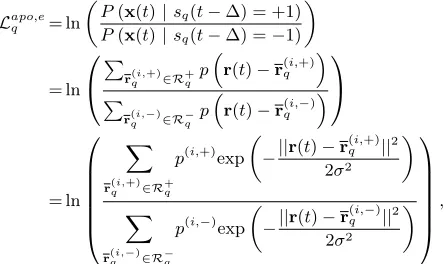
Bayesian DF-STE may be written as
L
apo,e q= ln
P
(
x
(
t
)
|
s
q(
t
−
∆) = +1)
P
(
x
(
t
)
|
s
q(
t
−
∆) =
−
1)
= ln
r(qi,+)∈R+q
p
r
(
t
)
−
r
(i,+)qr(qi,−)∈R−q
p
r
(
t
)
−
r
(i,−)q
= ln
r(qi,+)∈R+q
p
(i,+)exp
−
||
r
(
t
)
−
r
(i,+)q||
22
σ
2r(qi,−)∈R−q
p
(i,−)exp
−
||
r
(
t
)
−
r
(i,−)q||
22
σ
2
,
where
x
q,±i∈
R
q,±,
p
(i,+)and
p
(i,−)are the a-priori
probabili-ties of
r
(i,+)qand
r
(i,−)q, respectively. Assuming that the symbols
in the sequence
s
(i)= [(
s
(i)1)
Ts
T2
]
Tare statistically independent
of each other, the apriori probability of the channel state
r
(i)can
be obtained from the apriori bit LLRs as follows:
P
(
r
(i)) =
P
(
s
(i)(
t
))
=
Q
q=1 m+K
j=0
P
(
s
(i)q(
t
−
j
))
=
Qq=1 m+K
j=0
exp(
−L
apr,eq,t−j/
2)
1 + exp(
−L
apr,eq,t−j)
exp(
s
(i)
q
(
t
−
j
)
L
apr,eq,t−j/
2)
,
where
L
apr,eq,t−jis the apriori information of the bit associated with
the
q
thuser at time instant
(
t
−
j
)
and
s
(i)q
(
t
−j
))
is associated
with the symbols in the sequence
s
(i). Depending on the sign
of
s
(i)q(
t
−
∆)
,
P
(
r
(i))
belongs to
p
(i,+)or
p
(i,−). Despite the
lower computational cost of the Bayesian DF-STE compared to
the STE using no feedback [3], the complexity imposed remains
high. In this paper the algorithm presented is therefore only used
as a benchmarker.
IV. INTERFERENCE CANCELLATION BASED
DETECTION
In contrast to the joint detection strategy discussed in the
previous section, one may also consider the interference
cancel-lation based turbo detection scheme illustrated in Figure 1(b).
The philosophy of this scheme is based on the principle that
with the aid of prefiltering, which is indicated as
R
−q12in
Figure 1(b) all interfering transmitters may be considered to
contribute additional white noise. The STE scheme represented
by SU-STE in Figure 1(a) then only has to be designed for
a single user. This has the advantage that in contrast to joint
detection schemes, the complexity of the system no longer grows
exponentially with the number of users.
In order to describe the system mathematically, the system
equation (3) is rewritten as the sum of all users’ transmitted
signals, yielding
x
(
t
)
=
Q
q
H
qs
q(
t
)
, . . . , s
q(
t
−
m
+ 1)
T T+
η
1(
t
)
T, . . . ,
η
L(
t
)
TT=
Qq
H
qs
q(
t
) +
η
(
t
)
=
Qq
x
q(
t
) +
η
(
t
)
,
(7)
where the
(
Lm
×
K
+
m
−
1)
-dimensional matrix
H
qconsists
of the columns of the matrix
H
, which are associated with
transmitter
q
. In the proposed PIC scheme we now define the
channel output generated by the
q
thtransmitter as
x
q(
t
) =
x
q(
t
) +
Q
n=q
x
n(
t
) +
η
(
t
)
.
(8)
This yields a channel output after the PIC stage of Figure 1(b)
at iteration
j
, which can be written as
˜
x
(j)q
(
t
) =
x
q(
t
)
−
Qn=q
H
n˜
s
(j−1)n(
t
)
,
(9)
where
˜
s
(j−1)n(
t
) = [˜
s
(i−1)(
t
)
. . .
˜
s
(i−1)(
t
−
m
−
K
)]
Twith
˜
s
(i−1)(
t
) = tanh(
L
apo,dn,t
/
2)
[2] being the symbol vector
con-taining the soft symbols associated with user
q
after the
(
j
−
1)
thPIC iteration. In general the MAI may not be considered as white
noise, unless the number of users is high. Hence the covariance
matrix of the interference experienced by the
q
thuser’s signal is
given as
R
q,M AI(
t
) =
Qn=q
x
n(
t
)
x
n(
t
)
H=
Q
n=q
H
nΛ
n(
t
)
H
Hn,
(10)
where
Λ
n(
t
)
is a diagonal matrix with
diag (Λ
n(
t
)) = [1
−
|
s
˜
n(
t
)
|
2. . .
1
− |
s
˜
n(
t
−m
−K
)
|
2]
. For MAI contributions which
may not be considered as white noise, the matrix
R
q,M AI(
t
)
will have non-zero off-diagonal elements. Taking into account
the additional effects of the channel-induced white noise, the
covariance matrix of the noise plus MAI associated with the
q
thuser may be written as
R
q(
t
) =
R
q,M AI(
t
) + 2
σ
n2I
Lm,
(11)
where
I
Lmis the
(
Lm
×
Lm
)
-dimensional identity matrix. The
whitening of the signal after PIC can now be expressed as
a matrix multiplication of the received signal vector
x
qwith
R
q(
t
)
−1
2
, which can be calculated using for example eigenvalue
decomposition. Following whitening, the resultant covariance
matrix of the MAI plus noise term is equal to the identity
matrix, which implies that the signal vector after whitening may
be considered to be contaminated by white noise having unity
variance.
The single-user multiple antenna equalizer indicated in
Fig-ure 1(b) as SU STE now has to be designed for the whitened
signal space following the approach outlined in Section III-B
where we now define the set of legitimate channel output states
as
R
±q
(
t
) =
r
(i,±)q
=
R
q(
t
)
− 12
H
1s
1if
s
q(
t
−
∆) =
±
1
.
(12)
The noise level considered by the Bayesian equalizer incorporated
in the PIC scheme is now not
2
σ
2n, but simply unity, since the
whitening filter has scaled the signal space accordingly.
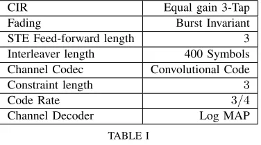
[image:3.595.60.284.128.260.2]CIR
Equal gain 3-Tap
Fading
Burst Invariant
STE Feed-forward length
3
Interleaver length
400 Symbols
Channel Codec
Convolutional Code
Constraint length
3
Code Rate
3
/
4
Channel Decoder
Log MAP
TABLE I
SIMULATIONPARAMETERS
which is passed through a whitening filter to the single-user
DF-STE. The extrinsic information obtained by the equalizer
is passed through a deinterleaver to the channel decoder, which
uses it as apriori information. The extrinsic information of each
channel decoder is passed back to the associated DF-STE of
the same receiver chain and the resultant aposteriori information
is passed back to the IC stage. The IC uses the aposteriori,
rather than the extrinsic information of the channel decoders,
because we assume the information obtained by the different
users’ receiver chains to be uncorrelated with each other. The IC
stage removes the remodulated and re-encoded soft information
of the interfering transmitters and re-calculates the whitening
filter matrices using Equation (10) and Equation (11) taking into
account the detected and removed MAI obtained in the previous
iteration. The DF-STE now uses the extrinsic information of the
channel decoder. A new iteration of the PIC scheme is always
based on two new inputs to the DF-STE, namely an input signal
contaminated by less interference than in the previous iteration,
and secondly the extrinsic information provided by the channel
decoder obtained in the previous iteration.
Note that the exact calculation of the whitening filter at each
symbol instant would require an eigenvalue decomposition of
the covariance matrix for each received symbol of each user.
Even with the advent of tracking the inverse of the covariance
matrix this would impose an unacceptably high complexity on
the receiver. Assuming burst-invariant or relatively slow fading
we therefore approximate the covariance matrix of the MAI as
R
q,M AI=
R
q,M AI(
t
) =
Qn=q
H
nΛ
n(
t
)
H
Hn,
(13)
where we have
Λ
n(
t
) =
H
nH
HnF1F
1
− |
s
˜
n(
t
)
|
2
, i.e the
apriori information obtained from the channel decoders is
approx-imated by its time average value over a transmission frame of
F
number of BPSK symbols. With the advent of this approximation
the whitening filter only has to be calculated once per PIC/turbo
iteration for each user, resulting in a significant complexity
reduction.
V. PERFORMANCE COMPARISON FOR
BURST-INVARIANT FADING
The channel considered for all of our simulations was a
three-tap channel having symbol-spaced equal-gain taps, where
all propagation paths of the channel were faded independently.
Additionally, the fading of the channel gains associated with
different antenna array elements at the BS was assumed to be
uncorrelated. The signals transmitted by the different users were
assumed to be received at an equal
E
b/N
0level. All other
simulation parameters are summarized in Table I.
10-5
10-4
10-3
10-2
10-1
100
0 1 2 3 4 5 6 7 8
BER
Eb/N0 [dB] 4Tx MMSE
[image:4.595.78.266.45.150.2]3Tx MMSE 2Tx MMSE 4Tx PIC 3Tx PIC 2Tx PIC 3Tx Bayes 2Tx Bayes
Fig. 2. BER versusEb/N0performance for a two-element BS receiver
using a feed-forward order of m = 3 after I = 6 turbo iterations.
The channel was assumed to be perfectly known by the receiver and all transmitters’ signals were received at equal average power.
Figure 2 shows the average BER of supporting Tx=2,3 and 4
uplink MS transmitters versus
E
b/N
0for a two-element receiver
at the BS. It can be observed that for two MS transmitters
indicated by ”2Tx” the joint Bayesian turbo detector described
in Section III-B represented by ”Bayes” and the PIC based
Bayesian DF-aided Turbo STE introduced in Section IV indicated
as ”PIC” perform similarly. By contrast, the BER performance
of the MMSE based joint detector indicated as ”MMSE” is
poorer and it can be observed that its BER curve tends to flatten
out for higher values of
E
b/N
0. Overloading the system by
supporting an additional MS transmitter (”3Tx”) degrades the
performance of the joint and the PIC based Bayesian detector
only marginally, whereas the MMSE based detector falters. For
the four- transmitter (”4Tx”) scenario the PIC based detector also
starts to struggle and a flattening of its BER curve comparable to
that of the MMSE detector is observed. The BER performance of
the joint Bayesian turbo DF-STE supporting four MS transmitters
has not been portrayed due to the high computational complexity
required for its simulation.
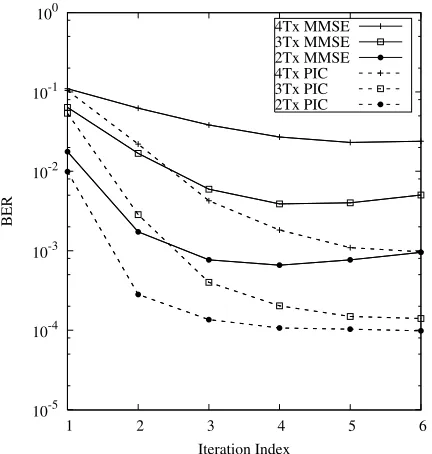
1When considering Figure 3, which shows the BER versus
iteration index performance at
E
b/N
0= 8
dB for the same
setup as used for the scenarios characterized in Figure 2, it
can be observed that both the joint MMSE and the PIC based
receiver produce a similar BER after the first iteration. However,
after the first iteration the PIC based receiver converges faster
to a lower BER. It is also apparent that for two users the BER
associated with the MMSE based detector increases slightly for
a higher iteration index. The authors believe that this effect is
imposed by the relatively weak 3/4-rate channel codec, since this
phenomenon has not been observed for channel codecs with a
stronger error correction capability (
R
=
12), which are often
used in the context of turbo equalization [4]. More explicitly,
1Note that in [4] no error floor associated with the MMSE detector
was observed because the system considered therein uses a convolutional
code with rateR= 1/2in conjunction with a less overloaded system.
10-5
10-4
10-3
10-2
10-1
100
1 2 3 4 5 6
BER
[image:5.595.67.283.47.274.2]Iteration Index 4Tx MMSE 3Tx MMSE 2Tx MMSE 4Tx PIC 3Tx PIC 2Tx PIC
Fig. 3. BER versus iteration index for a two-element receiver using
a feed-forward order ofm= 3atEb/N0 = 8dB. The channel was
assumed to be perfectly known by the receiver and all transmitters’ signals were received with equal average power.
in the case of a weak channel codec, the MMSE turbo receiver
tends to require more iterations and relies more on the fact that
all channel decoders provide reliable extrinsic information for
the STE, which is uncorrelated with the output information of
the STE itself. If, however, the information provided by the STE
is error-infested and hence the channel codec introduces more
errors than it had at its input, then an increased BER may be
observed, as shown in Figure 3.
In Figure 4 the average BER of all user scenarios versus the
E
b/N
0performance of a four-element BS receiver is shown. The
signals transmitted by the different users are again assumed to
be received with equal power. It can be seen that the PIC based
receiver outperforms the joint MMSE receiver and achieves even
for eight MS transmitters at near-single-user performance.
VI. COMPLEXITY
It has been shown in Section V, that the PIC based non-linear
receiver structure is capable of outperforming joint MMSE turbo
detection. In this section we will provide a short
complexity-related discussion of the different receiver schemes considered.
It was shown in [3] that the matrix inversion, which dominates the
complexity of the MMSE based turbo detector, can be recursively
calculated using the matrix inversion lemma. The recursively
up-dated soft output can then be obtained at the cost of a complexity,
which is on the order of
O
(
L
2(
m
2+
K
2))
. The complexity
of the DF-assisted Bayesian turbo detector is dominated by the
number of noiseless channel output state calculation, which is
proportional to
O
(2
Q(∆+1))
. The complexity estimate of the
PIC based detector consists of three components. The parallel
interference cancellation operation, which can be accomplished
at a complexity on the order of
O
(
L
2(
m
2+
Km
))
, the whitening
of the signal at
O
(
L
2m
2)
and the single user equalizers, which
impose a complexity contribution proportional to
O
(
QLm
2
∆+1)
.
The complexity of the full Bayesian detector may be deemed
excessive for practical real-time applications. Although the
com-plexity of the PIC based detector scheme is proportional to the
10-6
10-5
10-4
10-3
10-2
10-1
100
0 1 2 3 4 5 6
BER
Eb/N0 [dB]
8Tx MMSE 1Tx MMSE 8Tx PIC 1Tx PIC
Fig. 4. BER versusEb/N0performance for a four-element BS receiver
using a feed-forward order of m = 3 after I = 6 turbo iterations.
The channel was assumed to be perfectly known by the receiver and all transmitters’ signals were received at equal average power