Faculty of Mechanical Engineering
NUMERICAL SIMULATION OF FLOW INSIDE
INTAKE MANIFOLD FOR SPARK IGNITION WITH PCC
Zulfadli Bin Mohamad Nazer
Bachelor of Mechanical Engineering with Honours
NUMERICAL SIMULATION OF FLOW INSIDE INTAKE MANIFOLD FOR SPARK IGNITION WITH PCC
ZULFADLI BIN MOHAMAD NAZER
A report submitted
in fulfilment of the requirements for the Bachelor of Mechanical Engineering with Honours
Faculty Mechanical Engineering
DECLARATION
I declare that this thesis entitled “Numerical Simulation of Flow Inside Intake Manifold for Spark Ignition Engine with PCC” is the result of my own research except as cited in the references. The thesis has not been accepted for any bachelor and is not concurrently submitted in candidature of any other bachelor.
Signature : ...
Name : ZULFADLI BIN MOHAMAD NAZER
APPROVAL
I hereby declare that I have read this thesis and in my opinion, this thesis is sufficient in terms of scope and quality for the award of Bachelor of Mechanical Engineering with Honours
Signature : ……….
Supervisor Name : DR. FUDHAIL BIN ABDUL MUNIR
APPROVAL
I hereby declare that I have read this thesis and in my opinion, this thesis is sufficient in terms of scope and quality as a partial fulfillment of Bachelor of Mechanical Engineering with Honours.
Signature : ……….
Supervisor Name : DR. FUDHAIL BIN ABDUL MUNIR
DEDICATION
I would like to dedicate to
My father,
MOHAMAD NAZER BIN ABDULLAH
My mother,
NORAINI BINTI ZAINUL
My supervisor,
DR. FUDHAIL BIN ABDUL MUNIR
And
All my friend,
i
ABSTRACT
ii
ABSTRAK
Manifold pengambilan adalah bahagian penting sesebuah enjin yang
membekalkan oxygen dan bahan api kepada kebuk pembakaran. Ia mempunyai pengaruh
besar terhadap prestasi enjin, pelepasan bunyi dan pencemaran udara. Objektif
penyelidikan ini adalah untuk mengkaji aliran di dalam manifold pengambilan bagi enjin
pembakaran dalaman dan potensi peningkatan dalam ciri-ciri reka bentuk manifold
pengambilan yang sedia ada. Manifold pengambilan di modelkan berbentuk tiga dimensi
menggunakan DesignModeler. Dalam kajian ini, enam reka bentuk manifold pengambilan
dimodelkan. Kesemua enam reka bentuk manifold pengambilan dilakukan simulasi
campuran udara minyak dari kemasukan manifold hingga ke kebuk pembakaran
menggunakan perisian ANSYS FLUENT 16.0. Dalam mengkaji keputusan simulasi,
didapati bahawa , sudut lenturan manifold pengambilan memberi kesan kepada aliran di
dalam manifold pengambilan. Selain itu, kecekapan volumetric boleh ditingkatkan dengan
iii
ACKNOWLEDGEMENT
First of all, I would to say “Alhamdulillah” (Praise to Allah) with His bless. I am very thankful for giving chances and ability to complete this project. In addition, I would like to thanks fellow friends who always helps and encouraged me with this project.
Noted with thanks to my helpful supervisor, Dr. Fudhail Bin Abdul Munir whose help, stimulating suggestions and encouragement helped me in all the time of the research and writing of this “Projek Sarjana Muda”. All of the support and supervise from him is completely useful and it will not be forgotten. The opportunity he had willingly given to me is a very substantial key for me to serve better for the industry and educational field particularly.
iv
TABLE OF CONTENTS
DECLARATION DEDICATION
ABSTRACT i
ABSTRAK ii
ACKNOWLEDGEMENTS iii TABLE OF CONTENTS iv LIST OF TABLES vi LIST OF FIGURES vii LIST OF ABBRIVIATIONS viii LIST OF APPENDIX xi CHAPTER
1. INTRODUCTION
1.1 Background 1
1.2 Problem Statement 2
1.3 Objectives 3
1.4 Scope of Project 3
1.5 General Methodology 3
2. LITERATURE REVIEW 2.1 Introduction 5
2.2 Flow Inside Intake Manifold 5
2.3 Pre-Combustion Chamber 10
2.4 Simulation Intake Manifold and Pre-Combustion Chamber 12
3. METHODOLOGY
3.1 Introduction 21
3.2 Intake Manifold Single Cylinder Modelling 23
3.3 ANSYS FLUENT 26
3.3.1 Pre-Processing
3.3.1.1 Geometry Modification 27
3.3.1.2 Meshing 29
3.3.2 Solver Setting 33
3.3.2.1 Material 34
3.3.2.2 Boundary Condition 35
3.4 Perform Simulation and Analysis Result 37
v
4. RESULT AND DISCUSSION
4.1 Overview 38
4.2 Different Angle of Intake Manifold 39
4.3 Tumble Pattern 42
4.4 Selection Best Design of Intake Manifold 47
5. CONCLUSION AND RECOMMENDATION
5.1 Conclusion 49
5.2 Recommendation 50
REFERENCES 52
APPENDICES 55
vi
LIST OF TABLES
TABLE TITLE PAGE
3.1 Side View and Isometric View of Designs Intake Manifold 27
3.2 Statistics Mesh 30
3.3 Side View and Isometric View of Meshing of Intake Manifold 31
3.4 General Setup 33
3.5 Model Setup 34
3.6 Aluminium Properties 34
3.7 Methane Properties 34
3.8 Material Setup 35
3.9 Boundary Condition 35
3.10 Solution Setup 36
4.1 Velocity Contour of 120° and 90° of Intake Manifold 39
4.2 Pressure Contour of 120° and 90° of Intake Manifold 41
vii
LIST OF FIGURES
FIGURE TITLE PAGE
1.1 Intake Manifold 4-Cylinder Engine 2
1.2 Flow Chart of the Methodology 4
2.1 Intake Manifold with Features 6
2.2 Variation of Specific Fuel Consumption with Engine Speed for 9
Different Intake Plenum Volumes 2.3 The Process of Project 13
2.4 Velocity Distribution inside Intake Manifold 15
2.5 Streamline Distribution inside Intake Manifold 15
2.6 Elements in CFD Simulation 16
2.7 Type 3 PCC Velocity Vectors (Maximum velocity = 1.14m/s) 16
2.8 Contours of Turbulence Kinetic Energy (TKE) for Type 2 17
2.9 Contours of Turbulence Kinetic Energy (TKE) for Type 3 17
2.10 Percentage Change in Volumetric Efficiency (1200RPM vs 4800RPM) 19 3.1 Logo of ANSYS FLUENT 21
3.2 Flow Chart of the Methodology 22
3.3 Intake Manifold 120° Angle 23
3.4 Intake manifold 90° Angle 24
3.5 Intake Manifold with Surge Tank 24
3.6 Intake Manifold with Surge Tank and Bell Mouth 25
3.7 Short Intake Manifold 25
3.8 Short Intake Manifold with Surge Tank 26
4.1 Design 1 – 120° Intake Manifold 42
4.2 Design 2 - 90° Intake Manifold 43
4.3 Design 3 – Intake Manifold with Surge Tank 43
4.4 Design 4 – Intake Manifold with Surge Tank and Bell Mouth 44
viii
LIST OF ABBRIVATIONS
PCC - Pre-Combustion Chamber 3D - Three-Dimensional
ICE - Internal Combustion Engine PFI - Port Fuel Injection
BT - Brake Torque BP - Brake Power
BMEP - Brake Mean Effective Pressure VE - Volumetric Efficiency
AFR - Air Fuel Ratio SI - Spark Ignition
ix
LIST OF APPENDIX
APPENDIX TITLE PAGE
A1 GANTT CHART PSM 1 55
A2 GANTT CHART PSM 2 56
B1 GEOMETRY INTERFACE ANSYS-FLUENT 16.0 57
B2 MESHING INTERFACE ANSYS-FLUENT 16.0 58
B3 SETUP AND SOLUTION INTERFACE ANSYS-FLUENT 16.0 59
1
CHAPTER 1
INTRODUCTION
1.1 BACKGROUND
Gasoline engine is a type of internal-combustion engine that produces power by burning a volatile liquid fuel, gasoline or gasoline mixture. There were several type of gasoline engine, which is four-stroke gasoline engine, two-stroke gasoline engine and rotary gasoline engine (Cromer, O.C et al., 2013). Nowadays, a four-stroke is common uses in automotive sector. Most vehicle on the road today is using Four-Stroke gasoline engine. Generally, combustion will occur inside the engine. Then, the air will pass through the intake and intake manifold before entering the cylinder engine for combustion.
2
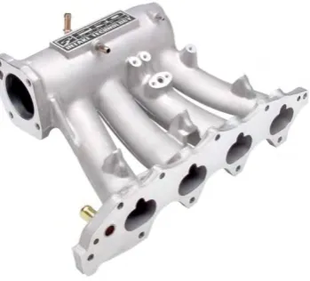
Figure 1.1: Intake Manifold 4-Cylinder Engine.
Nowadays, simulation in automotive sector is not a new thing. There has been a lot of simulation process to get a variety of data and study about something cannot be seen. Simulation is the method to get exactly results flow inside intake manifold. It can illustrated how the movement of flow and the characteristic through intake manifold. The simulation can be repeated as many as needed until best result is achieved.
1.2 PROBLEM STATEMENT
3
1.3 OBJECTIVE
The objectives of this project are as follows:
1. To develop a workable numerical model of intake manifold for spark ignition engine with PCC
2. To perform numerical simulation using the developed numerical model
1.4 SCOPE OF PROJECT
The scopes of this project are:
1. Utilize ANSYS FLUENT as the simulation tools
2. Establish a three dimensional (3D) geometry of single-cylinder intake manifold 3. Perform cold flow simulation at the area of intake manifold
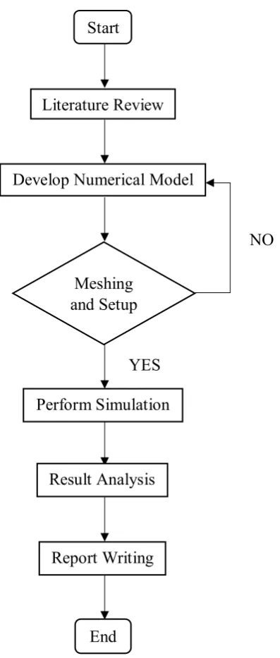
1.5 GENERAL METHODOLOGY
The actions that need to be carried out to achieve the objectives in this project are: 1. Literature review
2. Development of the numerical model 3. Perform simulation and results analysis 4. Report writing
4
Figure 1.2: Flow Chart of the Methodology Start
Develop Numerical Model
Meshing and Setup
Perform Simulation
NO Literature Review
Result Analysis
Report Writing
5
CHAPTER 2
LITERATURE REVIEW
2.1 INTRODUCTION
In this chapter, the literature review of numerical simulation flow inside intake manifold for gasoline engine with PCC is presented for background information in order to understand. The research presented in this paper has been reviewed from various source such as journal, article and website.
2.2 FLOW INSIDE INTAKE MANIFOLD
6
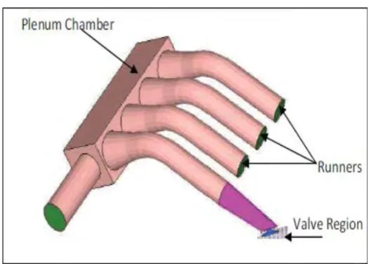
Figure 2.1: Intake Manifold with Features (Priyadarsini, 2016)
The air flow inside intake manifold convey flow evenly to the piston valve is one the important factors. Flow phenomenon inside the intake manifold should be completely enhanced to create more engine power with better ignition and decrease the emission. Researcher performed numerical analysis of flow of intake manifold by modelled three-dimensional intake and analysed by using the FLUENT software to study the pressure, velocity and flow characteristic. The anticipate result of pressure loss and total outlet mass flow. Intake pipe and plenum connection construct a back step geometry which causes more aggregate pressure loss because of flow distribution in conventional model. Further intake mass flow to devaluation in total pressure loss in the plenum chamber due to tapering geometry (Priyadarsini, 2016).
7
results of the experiment, the length of runner intake manifold influences on fuel consumption (Tsogtjargal et al., 2012).
The incompressible stream in the intake pipe of laboratory-scale internal combustion engine at Reynolds numbers relating to reasonable working conditions was studied with the assistance of direct numerical simulations. The mass flow through the bended pipe remained consistent and the valve was held permanent at its halfway-open position, as is commonly done in steady flow engine test bench experiment for the improvement of intake manifold. The flow features were distinguished as the flow develops in the bended intake pipe and connects with cylindrical valve stem. Researcher discovered that the flow can become turbulent rapidly on the inflow profile forced at the pipe inlet, although no extra noise was added to impersonate turbulent velocity fluctuations. Improvement of the geometry of the intake and exhaust ports/valves, piston and cylinder has turn to an essential part of ICE development, to enhance the efficiency and decrease pollutant emissions to conform with stringent environmental regulations and to present novel combustion concept. Normally, the study and improving of the intake manifold aiming at upgrading the generation of the cylinder swirling motion, and the measurements the valve’s discharge coefficient, is carried out in steady flow engine test benches at permanent valve positions (Giannakopoulos et al., 2017).
8
primary use of an intake manifold is to transfer as much air-fuel mixture to the combustion chamber as possible.Researcher analyzed computational fluid dynamics to investigate the air flow behaviour inside a different intake manifold angles. The method is using ANSYS CFX simulation tool by taking six angles of intake manifold which are 30°, 60°, 90°, 120°, 150°, and 180°. Simulation by researcher found that high intake manifold will give better air flow inside intake manifold. This is because of lower air resistance caused by the curved manifold (Mohd Faisal Hushim et al., 2016).
9
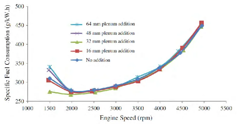
Figure 2.2: Variation of Specific Fuel Consumption with Engine Speed for Five Different Intake Plenum Volumes (Ceviz et al., 2010).