IMPROVING FLEXURAL BEHAVIOUR OF REINFORCED
CONCRETE BEAMS
I G Shaaban
Zagazig University
Egypt
ABSTRACT. A new technique for using expanded wire fabric (EWF) as additional
reinforcement and permanent formwork for reinforced concrete beams is proposed. Five beam specimens were experimentally tested, namely, an under reinforced control beam containing only conventional reinforcement and other four beams additionally reinforced with EWF for shear and flexure. The studied parameters included the orientation of EWF, the amount of longitudinal and transverse EWF, and the method of application of EWF. The results showed that the use of EWF led to an improvement in deflection and ductility of test beams. In addition, beams reinforced with EWF showed better crack control in comparison with the control beam having only conventional reinforcement. The orientation and method of application of EWF have a great effect on flexural behaviour of beams. The beam reinforced with U shape EWF jacket and additional layer of EWF flexural reinforcement showed better properties compared with the other beams. Its load capacity was increased by 20%, strain reached the maximum of (0.014) and the crack widths were reduced by approximately 35% compared to the control beam with conventional reinforcement. A proposed formula was developed for predicting the effect of EWF on crack control. The results obtained by this formula were in good agreement with the experimental results.
Keywords: Expanded wire fabric, Crack control, Deflection, Ductility, Reinforcement
orientation, Flexural behaviour, Ferrocement.
I G Shaaban is an associate professor for the analysis and design of RC structures in Civil
INTRODUCTION
The rapid increase in the cost of construction has forced engineers to look for economical and better methods for building and/or repair of distressed structures. Among the materials used for construction and repair, ferrocement is comparatively a promising approach. Ferrocement is constructed of hydraulic cement mortar reinforced with closely spaced layers of small wire diameter mesh, or wire fabric, made of metallic or any other suitable material [1]. Ferrocement possesses a high degree of toughness, ductility, durability, strength and crack resistance within a relatively small thickness (approximately 25 mm), [2]. Combining these advantages with the fact that steel stresses of more than 550 MPa can be tolerated without excessive cracking, indicates a material which is ideally suitable for rehabilitation and/or new construction [2]. Hussin and Zakaria [3] and Nedwell and Swamy [4] reported that by proper choice of reinforcement and method of production, ferrocement pools, houses and boats were more economical than reinforced concrete ones. In Egypt, it is believed that the use of ferrocement in the construction can be a competitive modern building material because of its low cost in comparison with conventional concrete. Therefore, it can be considered one of the ideal solutions for the housing problem [5].
Recently, extensive research work has been carried out into ferrocement properties and applications [6 and 7]. Abdul Kadir et al [8] tested the flexural behaviour of sixteen simply supported RC beams with ferrocement permanent formwork. The test results showed that such beams failed by flexure. The composite beam with shear connectors carried about 12% higher load and 10% reserved flexural strength and showed lower deflection when subjected to the same loads as compared to reinforced concrete beams without shear connectors. Lin and Pcrng [9] investigated the flexural behaviour of beams with welded wire fabric (WWF) as shear reinforcement. The parameters studied in their research included concrete strength, shear span to depth ratio, amount of fly ash, amount of longitudinal reinforcement and amount of transverse reinforcement. It was found that beams with WWF shear reinforcement exhibit higher strength, better ductility and crack control than those with conventional shear reinforcement due to better confinement. In 1988, ACI Committee 549 [10] updated both of the guides for the design, construction and repair of ferrocement, and State-of-the-Art Report on Ferrocement. The main objective was to provide owners with a reference document to check the acceptability of a ferrocement alternative in a given application. However, since
1988 no update was issued to these documents [11].
The objective of this research is to study the use of expanded wire fabric (EWF) as a multipurpose material, as a formwork instead of the traditional wood formwork and as an additional reinforcement for reinforced concrete (RC) beams to improve flexural and shear behaviours of such beams. The results reported in this investigation are part of a wider research program study the potential application of EWF in RC beams. The studied parameters were the orientation of EWF, amount of longitudinal and transverse EWF, and the method of application of EWF. The behaviour of the test beams was monitored by measuring deflections, crack widths, horizontal and shear strains for different load stages.
EXPERIMENTAL PROGRAM
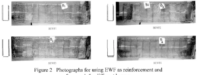
The dimensions, reinforcement of the control beam and the combination of conventional and EWF reinforcement used in the other test beams are shown in Figures 1 and 2. The control beam was cast in the usual manner. A formwork of EWF of diameter 1 mm and diamond shape was used as additional shear and flexural reinforcement for the other four test specimens as shown in Table 1 and Figure 2. Then the fresh concrete was poured in the middle of the beams until mortar started to pass through the EWF openings. After that the external surfaces of the EWF were plastered using semi-dry mortar until the EWF was fully coated with mortar. The parameters investigated were amount of EWF for flexure and shear, EWF orientation and method of application.
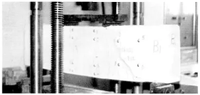
All the specimens were tested under monotonic loading. A 50 ton Shimadzu universal testing machine with a computer controlled hydraulic servo system was adopted to apply loads. The load was spread into two point loads on the beams at a 1 mm/min rate of loading. Demec studs were glued to the sides of the test beams. Three groups were fixed on one side of each beam for the measurement of concrete surface strains and principal strains at various locations on the top compression and bottom tension surfaces of the beams. The measurements were carried out using a 100 mm demountable digital demec gauge. The deflections were measured using dial gauges (0.01 mm divisions) fixed on the bottom surfaces of the test beams. Crack widths were also observed and measured before yield. The load-deflection curve was plotted during test. Figure 3 shows a schematic diagram for a simply supported typical test beam with load position and demecs fixed at its side. It can be seen from Figure 3 that shear span/depth ratio of studied beams was kept constant (0.4/0.3).
t:\VI: application (sec Table 1 )~
71O7-Figure 1+ A typical studied beam specimen; (a) Sectional elevation for reinforcement details; (b) Cross section of control beam; (c) Cross section of Beams reinforced with EWF.
+
[image:3.443.55.387.315.391.2](Dimensions are in cm, lem = 10 mm)
[image:3.443.51.394.445.576.2]p / 2
0.05. 0.15 - 0.14 .. 0
1
, 0 . 1 .,0,1 .. C
p / 2
gl ,. 0.14 ,. 0.15
f?
58+ -+-7
7 4 - 4-8 3*.
44-• 3 I O
54- +6
'p/2
0,p_5i 0.4 0.4 0,4
p / 2
[image:4.443.93.362.55.206.2]1.30
Figure 3 Loading arrangement and demec points for a typical test beam.
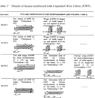
Table 1
+Details of beams reinforced with Expanded Wire Fabric (EWF)
Specimen TYPE AND ORIENTATION OF EWF REINFOREEMENT(SEE FIGURES 1 ADN 2)
BEWF1
One Jacket of EWF (U shape, * Orientation -30°).
-130 *
Wings of EWF (U shape) each of width equals 5 cm and spaced at 20 cm (*Orientation = t
One Jacket of EWF (U shape, * Orientation = 30°).
r .130 >
. 3 0 °
Wings of EWF (U shape) each of width equals 5 cm and spaced at 20 cm (•Orientation = 45°).
BEWF3
Two side strips of EWF for shear reinforcement, 25 x 130 cm each, •Orientation = 30°.
One horizontal strip of EWF for flexure reinforcement at bottom of the beam, 32 x 130 cm, *Orientation = 30°.
Vertical strips of EWF for shear reinforcement each of width equals 5 cm, 25 cm height and spaced at 20 cm (* Orientation = 45°).
- 3 0 ° 130
One Jacket of EWF (U shape, • Orientation = 45°).
One horizontal strip of EWF for flexure reinforcement at bottom of the beam, 12 x 130 cm, *Orientation = 30°.
12
-=*—30*
*Orientation angle is measured from the horizontal direction
+
[image:4.443.92.400.222.540.2]RESULTS AND DISCUSSION General Behaviour and Crack Pattern
The observed crack patterns till brittle shear failure for a typical test beam reinforced with EWF (BEWF1) are shown in Figure 4. The crack patterns developed similarly for all the beams reinforced with EWF. First cracking usually occurred at a higher load than in the control beam (see Figure 5). Initially, the cracks were vertical, as would be expected for flexural cracks, but later they would bend over in the shear regions. Crack widths of the beam specimens reinforced by EWF were generally smaller than that of beams reinforced by conventional reinforcement. After the control beam specimen reached its peak load, the concrete cover started to spall. Concrete cores of the beam specimens with EWF reinforcement remained more intact than those of specimens with conventional reinforcement after spalling of concrete cover due to the fact that the spaces of EWF were smaller and they provided better confinement.
Load-Deflection Relations
[image:5.443.117.320.330.427.2]The load deflection relationships for the control beam BO and the other beams reinforced with EWF are shown in Figure 5. Before yielding of the flexural reinforcement, the load-deflection curves were quite linear. It can be seen from the figure that the use of EWF as a formwork and additional reinforcement led to an increase in beam's capacity by approximately 5-20% without the use of wooden formwork. It is worth mentioning that the increase in beam's capacity to 20% was achieved by using one layer only of EWF for reinforcement.
Figure 4 A typical test beam reinforced with EWF during testing.
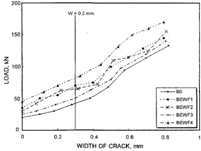
Crack Width
[image:6.443.91.336.124.286.2]Widths of flexural cracks were measured during the tests and crack widths of the different beam specimens were compared. Typical load versus crack width curves is shown in Figure 6. It can be seen that beams with EWF reinforcement showed better crack control over the control beam BO.
< o Q uj
a.
<
2 4 6 8 10 12 14 16 18 20
MID-SPAN DEFELECTION, mm
Figure 5 Load deflection relationships for different studied beams.
The loads at allowable crack width proposed by ACI code, which is about 0.3mm, can be also used for comparison |9]. Loads on the beams reinforced with EWF were generally higher than those on the control beam BO. It can be seen from Figure 6 that the beam BEWF4 had the minimum crack widths compared with the other beams reinforced with EWF. This may be attributed to the fact that this beam has a combination of good confinement, as a result of using U shape EWF jacket, and closely spaced wires, as a result, of using two layers of EWF in flexural reinforcement.
w 0.3 mm
X
- -"•--BEWF1 - ^ < - B E W F 2 - • • - - BEWF3 - -4 - BEWF4
0.2 0.4 0.6
[image:6.443.118.320.417.569.2]WIDTH OF CRACK, mm
Strains
(a) Horizontal strains
The measurement of the horizontal strain distribution across the depth of the test beams for different load steps were recorded and plotted in Figure 7. It can be seen from the figure that the tensile strains were much higher than the compressive strains and the strain distribution was almost linear across the beam depth except for beam BEWF1. This finding reflected the ductile behaviour of the beams as the tensile reinforcement reached its yield strength. The horizontal strain results measured at the demec points (1-4) on the sides of beams (see Figure 3) were highly affected by the formation of cracks. It can be seen from Figure 7 that the strains in the tension zone increased slowly for different beams to different load levels before the formation of cracks. After the formation of cracks, the contribution of reinforcement led to a rapid and significant increase in strains until failure occurred. The contribution of EWF enhanced the ultimate capacity of the studied beams to different degrees. Figure 7 shows also that the horizontal strains at maximum ultimate loads of the studied beams ranged between 0.006 to 0.014. The beam BEWF4 had the maximum strain (0.014) at a maximum ultimate load (160 kN) which indicates the high ductility of this beam compared with the control beam and the other beams reinforced with EWF. This is in good agreement with the findings observed earlier for the load-deflection relationships and crack widths.
(b) Principal tensile strains
The relationship between applied loads and principal tensile strains is shown in Figure 8. It can be seen from the figure that reinforcing beams with EWF improves both of the beams' capacity and ductility. As observed earlier for the horizontal strains, all the beams show slow increase in principal tensile strains before cracking. After cracking, only the EWF and steel reinforcement provide tensile resistance, and hence, principal tensile strains increases much more rapidly. Figure 8 shows that the beam BEWF4 sustained a higher load at low strain compared to that of the other studied beams. The other beams sustained almost equal loads at low strains till cracking, after cracking the beams reinforced by EWF showed higher resistance compared to the control beam B0. It is interesting to note that the order of improvement in the behaviour of beams reinforced with EWF in principal tensile strains was not the same as that in horizontal strains. For example, despite that Specimen BEWF4 showed excellent ductility till failure, at a maximum load for horizontal strains compared with the other beams (see Figure 7), Specimen BEWF3 sustained ultimate principal tensile strains higher than that of BEWF4 by 65% (0.068 mm/mm) at almost equal loads (see Figure 8). This may be attributed to the fact that the amount of EWF for shear reinforcement of Beam BEWF3 was higher than those for Beam BEWF4 (see Table 1 and Figure 2).
THEORETICAL PREDICTION OF CRACK WIDTHS
The maximum crack width for square mesh reinforcement in flexural members was predicted earlier [1] as follows:
w
max= — - — sp (i)
Er
Where
fs = stress in the outermost layer of steel.
S = spacing of transverse wires.
[3 = ratio of distances to the neutral axis from the extreme tensile fibre and from the outer most layer of steel.
E 0.15 DE F O.OS Vt\\ V O 0,005 STRAIN, mm/mm
Control beam (B0)
O.3 0 0.005 STRAIN, rnm/mm Beam (BEWF3) -0.005 (1) e Q (3) [4> -O.OOS
0 0.005 0.01
STRAIN, mm/mm
Beam (BEWP1)
o.is .»5\\ \ .
0 0.005 0.01
STRAIN, mm/mm Beam (BEWF4) -O.005 Z ML O.O O 0-005 STRAIN, mm/mm Beam (BEWF2) 20 kN
— — - 40 kN
60 kN 80 kN
_ _ _ 100 kN — . — 120 kN
Figure 7 Strain distribution for studied beams.
<
o
^1 a. a. < \}
BO BEWF1 BEWF2 BEWF3 •—-BEWF40 0.001 0.002 0.003 0.004 0.005 0.006 0.007
PRINCIPAL TENSILE STRAIN, mm/mm
Figure 8 Load-principal tensile strain relationship for different studied beams
1 S 85
Wm a x= (1.194 fs- 111) (2)
Er
Where Wmax is in mm, fs and Er are in MPa (N/mm2).
The following conservative procedure [12] can be followed, assuming the stress in the steel is less than the yield strength and in any case less than 414 MPa, to predict maximum crack width in tensile ferrocement members:
For fs < 345 SrE
w _ 35000 n,
Wm a x- (3)
Er
Where
fs is in MPa, Wmax in mm and Er in (N/mm ).
Sre is the specific surface of reinforcement in loaded direction is cm"1 and is defined as
the total bonded area of reinforcement (interface area or area of the steel that comes in contact with the mortar) divided by the volume of composite.
For a ferrocement section of width b and depth h, the specific surface of reinforcement can be computed from
bh
In which So is the total surface area of bonded reinforcement per unit length (the perimeter of flexural reinforcement bars and EWF are considered in full contact with concrete).
For fs > 345 Srt (applicable for the studied beams in this investigation)
Wm a x= | ° [175 + 3.69 (fs- 345 Sr£)] (5)
The above equation is modified herein for the application to RC beams reinforced with EWF used in this study, as follows:
20 t
Wm a x= [175 + 3.69 (fs - 345 { I a Srt cos 9 + Srb})] (6)
Er 1
Where
Sr is divided into two terms, the contribution of longitudinal reinforcement bars (traditional
reinforcement) "Srb" and summation of specific surface of reinforcement for EWF layers, t
"Src" which includes strips, jackets, and wings. Since the predicted crack widths are the
9 is the orientation angle of EWF with the horizontal direction.
a is a confinement factor and is estimated as 16 for EWF wings or jackets, 8 if jackets and wings are acting together and 1 for EWF strips.
t ; = 140MPa(N/mm2).
Er in the longitudinal and transverse directions for EWF were reported in [10] as follows:
Er(iong)=138xl03(N/mm2). & Er(trans) = 69xlO3 (N/mm2).
The prediction of crack widths is normally carried out during service loads. However, the predicted crack widths obtained by the above equations are not functions in applied loads. Therefore, experimental values of crack widths, which are related to applied loads as shown in Figure 6, can not be compared with those predicted by Equation (6). It is more practical to compare the effect of EWF reinforcement on the crack widths obtained experimentally with that predicted theoretically. This effect can be estimated by;
Crack width of a beam reinforced with EWF, WEWF (7) Crack width of the control beam, Wo
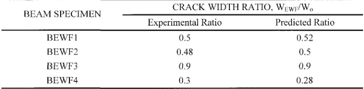
[image:10.443.44.401.420.508.2]The experimental effect of EWF is obtained on two steps. Firstly, by extracting crack widths for studied beams from Figure 6 at a load level less than the service loads, which are assumed to be half of the maximum test loads. Secondly, by applying Equation (7) to the experimental results. Predicted values of crack widths can be obtained by applying Equation (6) to each studied beam while the effect of EWF on predicted crack width is obtained by applying Equation (7). Table 2 shows a comparison between the experimental and predicted effect of reinforcing beams with EWF. The good agreement between the experimental and theoretical results shown in Table 2 indicates the sensitivity of Equation (6) to the studied parameters such as orientation of EWF, quantity of EWF reinforcement (number of reinforcement layers) and type of reinforcement (strips, jackets, wings and traditional reinforcement).
Table 2 Experimental and theoretical evaluation of EWF effect on crack width
CRACK WIDTH RATIO, WE WF / W0
BEAM SPECIMEN
Experimental Ratio Predicted Ratio
BEWF1 0.5 0.52
BEWF2 0.48 0.5
BEWF3 0.9 0.9
BEWF4 0.3 0.28
CONCLUSIONS
Using EWF as additional reinforcement results in a reduction of deflection, increasing loads at first cracking, and enhancing section ductility. In addition the close spacing between wires in the EWF can reduce crack widths.
The beams reinforced with a U-shaped EWF layer around the beam cross-section and additional layer at the tension face showed excellent response compared with other beams reinforced with EWF. Its load capacity was increased by 20%, strain reached the maximum of (0.014) and the crack widths were reduced by approximately 35% compared to the control beam with conventional reinforcement.
Using EWF as a permanent formwork is a promising technique since it can achieve two goals, firstly it can replace the traditional temporary timber formwork which, in turn, lead to a reduction of the overall cost and avoid problems of placing concrete. Secondly, it can be used as additional reinforcement for improving shear and flexure behaviour. However, further research is needed to study the potential application of this technique widely for beams of large spans.
A proposed formula was developed for predicting the effect of EWF on crack widths. The prediction was in a good agreement with the experimental results.
REFERENCES
1. ACI Committee 546, "State-of-the-Art Report on Ferrocement," (ACT 549 R-88), ACI, Detroit, 1988,24pp.
2. AHMED H.I, ROBLES -AUSTRIACO L, "State-of-the-Art Report on Rehabilitation and Restrengthening of Structures Using Ferrocement," Journal of Ferrocement, Vol. 21, No. 3, July 1991, pp. 243-258.
3. HUSSIN M.W, ZAKARIA F.H (Editors), "Ferrocement-Current Research, Applications and Developments", Proceedings of the Second National Seminar on Ferrocement, Johr Bahru, Malaysia, August 1993, pp. 129.
4. NEDWELL P.J, SWAMY R.N (Editors) "Ferrocement, proceedings of the Fifth international Symposium on Ferrecement", 1994, E@FN Spons, London, pp. 507.
5. PRAWEL S.P, REINHORN A, "A Competitive Modern Building Material," Concrete International, Vol. 5, No. 11, November, 1983, pp. 17-21.
6. MANSUR M.A, TAN K.L., NAAMAN A.E., PARMASIVAM, P. ,"Bolt Bearing Strength of Thin-walled Ferrocement", ACI Structural Journal, Vol. 98, No. 4, July 2001.
7. AL-KUBAISY M.A., JUMAAT M.Z., "Strengthening of Reinforced Concrete Beams Using Ferrocement Laminate", Concrete International, Vol. 22, No. 10, October, 2000, pp. 37-43.
9. LIN C.H, PERNG S.M, "Flexural Behaviour of Concrete Beams with Welded Wire Fabric as Shear Reinforcement," ACI Structural Journal, Vol. 95, No. 5, September-October 1998, pp. 540-546.
10. ACI committee 549, "Guide for the Design, Construction, and Repair of Ferrocement," (ACI 549. 1R-88), ACI Structural Journal, May-June 1988, pp. 325-351.
11. PARAMASIVAM P., LIM C.T.E., ONG K.C.G, "Ferrocement in Structural Upgrading and Rehabilitation-An Overview", ACI SP.193-22, Vol. 193, August 2000.
12. E.C 2000, "Egyptian Code for the design and Construction of Reinforced Concrete Structures", Cairo, 2000.