A Model-based Approach for Automatic Validation of Protection Settings
Qiteng Hong, Campbell D. Booth, Victoria M. Catterson, and Adam Dyśko
Institute for Energy and Environment, University of Strathclyde, Glasgow, UK
Abstract
The reliable operation of protection systems depends on the correct setting of protective devices. Due to the increasing network complexity and the large number of protective devices (and their associated setting parameters), it is extremely laborious for engineers to manually validate the settings. Existing model-based (MB) systems that are capable of performing the validation task require significant manual input for network models creation, relay models configuration, simulation result analysis, etc., which is both time consuming and subject to human errors. This paper presents a methodology that adopts the principle of model-based reasoning (MBR) for automated validation of protection settings. Such a methodology is demonstrated through the design and implementation of a prototype tool Model-Based protection setting Smart Tool (MBST), which is capable of automatically populating network models, configuring relay models with settings to be validated, creating credible system events, and simulating the relays’ behaviour under these events. The automated process is achieved by an interface layer within MBST that allows interaction with a commercially available simulation engine to leverage its internal data and functions for the settings validation task. The simulated results are automatically analysed using a rule-based (RB) approach. The key advantage of the work is the mechanism to automate the entire settings validation process. The design of the interface layer to interact with existing simulation engine and models also demonstrates a solution for rapid prototyping of intelligent systems dedicated to validation of protection settings.
1
Introduction
Protection systems defend power networks by detecting and isolating faults on the system, thereby minimising damage, the risks of wide-area blackouts and other unsafe or undesirable conditions. The reliable operation of protection systems depends on the correct setting and configuration of protective devices.
It has been realised that, despite multiple instances of checking, verification and quality control processes, relying solely on protection engineers for decision making and relay setting validation may lead to some unexpected (or hidden) errors [1]. These errors could result from erroneous calculations, from engineers' misunderstanding or mistranslating of the setting policies, or potential errors in the process of the application of settings to the protection devices. Failure in identifying these errors may result in in-service mal-operation events, or even large-area blackouts [2].
proposed design approach presented in this paper also demonstrates that the rapid prototyping of a protection settings validation system can be achieved by the use of existing simulation engine and its provided models through the proper design of the interface layer with the engine.
The paper is organised as follows. Section 2 introduces the MBR technique and discusses how the technique can be adopted for the validation of protection settings. Section 3 presents the design of the proposed settings validation system MBST. Section 4 presents the implemented MBST prototype based on the proposed methodology. In Section 5, discussion on the advantages of the proposed approach, its limitations in practice and potential improvements in the future are provided.
2
Model-based reasoning for the validation of protection settings
MBR is an AI technique that is widely used in power system applications such as protection operation validation [7], alarm processing [8], fault identification and location [9, 10], etc. The typical approach adopted in MBR systems is illustrated in Fig. 1, where the observed physical devices' behaviours (i.e. observations) are compared with the predicted behaviours (i.e. predictions) from the models. Any detected discrepancies are used for the diagnosis of failures of physical components. The heart of an MBR system is the reasoning engine that controls the propagation of data flow through the model and compare the simulated results to the real world data [11].
[image:2.595.209.387.452.551.2]For the validation of protection settings, although there is no physical device involved as in typical MBR applications, the principle of MBR can be adopted. As shown in Fig. 2, protection settings are applied to the relay models that are installed in appropriate network models, and simulated under a wide range of system events. In this case, the simulated results are referred as observations, which are compared to expected relay models' behaviours (referred to as expectations). Any discrepancies between the observations and the expectations indicate the existence of problems in settings or in the design of the protection system. It is clearly important and advantageous to identify any such discrepancies before deployment of the protection scheme. In this work, the detection of discrepancies is achieved through a RB approach, which is discussed further in Section 3.
Fig. 1. The principle of MBR [12]
[image:2.595.208.385.557.744.2]Fig. 3. The design of MBST
3
The design of Model-Based protection setting Smart Tool (MBST)
3.1 Overview
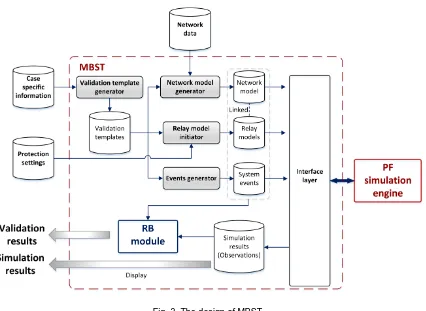
The architecture of MBST is shown in Fig. 3. The system contains the following main components: validation template generator, network model generator, relay model initiator, RB module (for automatic analysis of results) and interface layer.
The inputs to the MBST are the network data (retrieved from network database), the protection settings data, and case specific information (e.g. the relay type, protection scheme to be validated etc.). The outputs are the simulation results (observations) that can be reviewed directly and final validation results that are automatically analysed by the RB module.
The validation template generator creates validation templates based on the supplied case specific information. Depending on the equipment being protected and the protection scheme being validated, different validation templates may be defined and used. For a particular protection scheme of a particular network element, there may be a number of templates defined, within which the network model and the fault events to be used for simulation are specified.
Fig. 4. Example equivalent network model used for validation of differential protection scheme
[image:3.595.157.440.617.694.2]equivalent network model with different levels of details (i.e. the depth of the adjacent circuit to be included) may be used.
Fig. 4 shows an example of an equivalent network model for the validation of differential protection settings, where internal and external faults may be applied to test the stability and the sensitivity of the protection scheme with the given settings. Fig. 7 shows another example, where an equivalent model including more network elements is used for the validation of feeder distance protection. When the network model is created, the relay model initiator installs the relay models in appropriate locations in the network model and applies the settings.
The events generator is responsible for creating system events (e.g. faults) based on the validation template and the associated network models used. The generated fault events contain the information about the faulty equipment, fault location, fault types, and the fault impedance.
Since there are large numbers of protective devices in the network, each of which needs to be simulated using various validation templates and associated defined events, the amount of simulation results can be overwhelming. The RB module is provided for the automatic analysis of the simulation results to highlight any incorrect operation. The rules are in the form of “IF-THEN” clauses, where “IF” defines the conditions and “THEN” contains the conclusions that can be drawn when the conditions are met. In the case of analysing simulation results, the conditions define the expected relay behaviours (i.e. expectations) under certain validation template and fault events, and if there are inconsistencies between the observations and the defined expectations, the rules will be fired to indicate the existence of error(s) in the element that is operating incorrectly (e.g. a distance protection zone).
The validation template generator, network model generator, relay model initiator and events generator prepare all information required for simulation. The actual simulation is performed with the aid of an external simulation engine - a commercially available software tool - DIgSILENT PowerFactory (PF). The following section will discuss the selection of the appropriate simulation engine and the design of the interface layer to leverage the engine’s internal data and functions to perform the defined simulation process.
3.2 Selection of simulation engine and the design of the interface layer In this work, the PF simulation engine [6] is adopted for the following reasons:
It readily provides comprehensive relay models for most of the existing commercial protection relays.
It provides the interface that allows the manipulation of the internal simulation functions and data from external applications. This is achieved through the provided application program interface (API) (further discussed later). Similar approaches that use existing models and simulation engines from external applications are reported in [12, 13]
Practically, PF is widely used by the UK network operator to model the transmission network. The use of PF aligns well with the available network data.
In practice, the use of the PF simulation engine is not a unique or mandatory option. Any system that offers appropriate MB simulation engine and models, and provides access to their functions for external applications can be considered as candidates for this purpose. The methodology and design approach presented in this paper is equally applicable to other potential options available, but the implementation may be different depending on the interface provided by the simulation engine.
Fig. 5 shows a number of example functions that illustrate how the interface layer interacts with the PF simulation engine.
[image:5.595.194.397.298.665.2]Fig. 5. The interface between MBST with the PF simulation engine
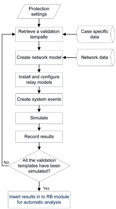
Fig. 6. The process for protection settings validation using MBST
3.3 Process of settings validation
1) Protection settings data, network data and case specific information (e.g. the protection scheme to be validated) are imported to the system.
2) Based on the imported case specific information, validation template generator retrieves an appropriate template for simulation.
3) The retrieved validation template is used by the network model generator to create a network model.
4) The relay models are installed in the created network model, and configured using the settings data to be validated.
5) A set of system events are automatically generated based on the information presented in the validation template.
6) The system events are simulated and the results are stored.
7) Start with another validation template until all the templates have been simulated.
8) The observations from the simulation are inserted to the RB module for automatic analysis.
4
The developed MBST prototype
A prototype MBST has been implemented based on the methodology and the design approach presented in this paper. The prototype successfully automates the entire settings validation process and indicates the incorrect operation of protection elements resulted from the errors in the settings. The current version of the prototype supports protection functions including feeder distance, differential and overcurrent protection relays and schemes.
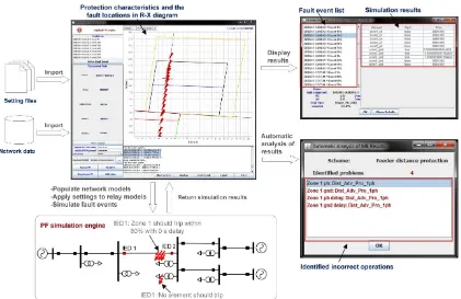
Fig. 7 shows the process of validating a feeder distance protection scheme using the MBST prototype. The setting files and network data are imported to MBST, based on which the protection characteristics (in this case the distance protection zone characteristics) and the feeder are plotted using an R-X diagram. A network model is populated in the PF simulation engine with pre-defined fault events applied (as shown at the bottom of Fig. 7). The locations of the faults are also displayed in the R-X diagram. The simulation results can be view directly to visualise the operation of the protection elements (tripping status, operating time etc.) within the relay models in response to a range of fault events (as shown on the top-right of Fig. 7). The results can also be automatically analysed using pre-defined rules as shown on the bottom-right of Fig. 7. There are two examples presented that show how the simulated results are analysed using rules. For IED 1, the ground zone 1 should be tripped for faults within 80% of the length of the protected line from the relaying point with 0 s delay and no protective elements should be active for a fault on the secondary side of the transformer. If observations do not conform to the expected operation (e.g. ground zone 1 does not trip for faults on the first 80% of the line length, or a zone element of the distance protection trips for a fault on the secondary side of the transformer), then messages will be generated to highlight the detected undesired operation and provide information on the particular settings that are responsible for the incorrect operation.
5
Potential improvements and future work
Fig. 7. The use of MBST prototype for the validation of protection settings
A more suitable approach for checking settings against policies is the RB approach, since most of the setting policies can be represented readily in the style of rules. It should be emphasised that the RB approach is used for validating protection settings directly against policy, and is complementary to the approach of using performance-based methods (i.e. MB methods) as discussed in Section 3 of this paper. The research on the use of RB approach for the settings validation against setting policies has been undertaken by the authors as reported in [15]. The disadvantage of the RB approach is that it can only detect the problems defined in the rule base and it is difficult to identify potential problems during the operation especially when there are multiple devices involved in a scheme. The RB approach is also at risk of not being able to identify any shortcomings or errors in the protection settings policies, which may be identified by the MB approach – hence the complementarity of the two approaches.
On-going and future work is therefore focussed in investigating the integration of the MBST system with the RB expert system as reported in [15], so as to develop a comprehensive solution for the validation of protection settings.
6
Conclusions
investigating the integration of the system with an RB element that allows checking of settings against settings policies to enhance the settings validation process.
References
[1] J. Sykes, V. Madani, J. Burger, M. Adamiak, and W. Premerlani, "Reliabilty of protection systems (what are the real concerns)," in Protective Relay Engineers, 2010 63rd Annual Conference for, 2010, pp. 1-16.
[2] Union of the Electricity Industry. Power Outages in 2003, 2004.
[3] T. A. Bopp, R. Ganjavi, R. Krebs, B. Ntsin, M. Dauer, and J. Jaeger, "Improving grid reliability through application of protection security assessment," in Developments in Power System Protection (DPSP 2014), 12th IET International Conference on, 2014, pp. 1-5.
[4] ETAP. (2015, 30/03). ETAP. Available: http://etap.com/
[5] Electrocon International Inc. (2015, 30/03). CAPE Software. Available: http://www.electrocon.com/
[6] DIgSILENT PowerFactory. DIgSILENT PowerFactory 15 User Manual, 2011.
[7] S. D. J. McArthur, A. Dysko, J. R. McDonald, S. C. Bell, R. Mather, and S. M. Burt, "The application of model based reasoning within a decision support system for protection engineers," Power Delivery, IEEE Transactions on, vol. 11, pp. 1748-1754, 1996.
[8] C. J. Edwards, E. M. Davidson, S. D. J. McArthur, I. Watt, and T. Cumming, "Flexible Model-Based Alarm Processing for Protection Performance Assessment and Incident Identification," Power Systems, IEEE Transactions on, vol. 28, pp. 2584-2591, 2013.
[9] A. Beschta, O. Dressler, H. Freitag, M. Montag, and P. Struss, "A model-based approach to fault localisation in power transmission networks," Intelligent Systems Engineering, vol. 2, pp. 3-14, 1993.
[10] R. Leitch, H. Freitag, A. Stefanini, and G. Tornielli, "Using the ARTIST approach for diagnosing power transmission networks," Intelligent Systems Engineering, vol. 3, pp. 125-137, 1994.
[11] S. D. J. McArthur, E. M. Davidson, G. J. W. Dudgeon, and J. R. McDonald, "Toward a model integration methodology for advanced applications in power engineering," Power Systems, IEEE Transactions on, vol. 18, pp. 1205-1206, 2003.
[12] E. M. Davidson, S. D. J. McArthur, and J. R. McDonald, "A toolset for applying model-based reasoning techniques to diagnostics for power systems protection," Power Systems, IEEE Transactions on, vol. 18, pp. 680-687, 2003.
[13] J. Mahseredjian, G. Benmouyal, X. Lombard, M. Zouiti, B. Bressac, and L. Gerin-Lajoie, "A link between EMTP and MATLAB for user-defined modeling," Power Delivery, IEEE Transactions on, vol. 13, pp. 667-674, 1998.
[14] DIgSILENT PowerFactory. DIgSILENT technical documentation PowerFactory API, 2011.
![Fig. 1. The principle of MBR [12]](https://thumb-us.123doks.com/thumbv2/123dok_us/1592459.111993/2.595.208.385.557.744/fig-the-principle-of-mbr.webp)