Rochester Institute of Technology
RIT Scholar Works
Theses Thesis/Dissertation Collections
3-5-2014
Inter-vehicular communication for collision
avoidance using Wi-Fi Direct
Chaitra Satish
Follow this and additional works at:http://scholarworks.rit.edu/theses
This Thesis is brought to you for free and open access by the Thesis/Dissertation Collections at RIT Scholar Works. It has been accepted for inclusion in Theses by an authorized administrator of RIT Scholar Works. For more information, please [email protected].
Recommended Citation
1
Inter-vehicular communication for collision
avoidance using Wi-Fi Direct
By
Chaitra Satish
A Thesis Submitted in Partial Fulfillment of the Requirements for the Degree of Master of Science in Telecommunication Engineering Technology
Department of Electrical, Computer and Telecommunications Engineering Technology
College of Applied Science and Technology
Rochester Institute of Technology Rochester, New York
[March 5, 2014]
Approved By:
____________________________________________________________________________________________
Dr.Clark Hochgraf, Professor, Primary Advisor Date
_____________________________________________________________________________________________
William Johnson, Professor, Committee Member Date
_____________________________________________________________________________________________
Mark Indelicato, Professor, Committee Member Date
2
Dedication
3
Acknowledgement
I would like to take the opportunity to thank my advisor Dr. Clark Hochgraf for his
immense support, patience and constant guidance throughout the course of this
research. I would also like to thank my family and friends for their unending support
4
Abstract
Inter vehicular collision avoidance systems warn vehicle drivers of potential
collisions. The U.S Department of Transportation (USDOT) National Highway Traffic
Safety Administration, in February 2014 has decided to enable vehicular
communication among lightweight vehicles to exchange warning messages to
prevent accidents [40].
Dedicated Short Range Communications (DSRC) is a communication
standard that allows short-range communication between vehicles and
infrastructure, exchanging critical safety information to avoid collision [10]. DSRC
safety applications include forward collision warning, sudden brake warning and
blind spot warning among many other warnings [10]. It is also important to
exchange location information between vehicles and pedestrians to avoid accidents.
To exchange safety messages using DSRC, dedicated equipment is required.
Pedestrians may not benefit from DSRC, as they may not carry dedicated DSRC
safety equipment with them.
Wi-Fi Direct technology can be used as an alternate to DSRC to exchange
safety messages. Wi-Fi Direct enabled smartphones can exchange important safety
information without the need of additional equipment. Peer-to-Peer (P2P)
connections are formed between Wi-Fi Direct devices to exchange safety
information. The Group Owner acts as the access point through which all clients
5
environment to exchange basic safety information between smartphones of vehicle
drivers.
Wi-Fi Direct and DSRC transmission delays are calculated are calculated. The
results show, with more devices in a Wi-Fi Direct group the congestion in the
network increases due to unnecessary retransmissions through the group owner. As
mitigation, a broadcast method is proposed to reduce the delay. The results
illustrate that the P2P group can now accommodate more vehicles and the delay is
lesser. The calculations are extended to compute the transmission delay when P2P
groups of same size exchange safety messages. The results help analyze the
6
Contents
Dedication ... 2
Chapter 1 Overview ... 12
Chapter 2 Dedicated Short Range Communication (DSRC)... 16
2.1 Introduction ... 16
2.2 DSRC bandwidth allocation ... 16
2.3 DSRC network components ... 17
2.4 Safety pilot program ... 19
Chapter 3 Wi-Fi ... 21
3.1 Background ... 21
3.1.1 Operation ... 22
Chapter 4 Wi-Fi Direct ... 25
4.1 Comparing DSRC and Wi-Fi Direct ... 25
4.2 Wi-Fi Direct in a vehicular environment... 26
4.3 Architecture ... 28
4.3.1 P2P groups ... 28
4.3.2 Concurrent operations by Wi-Fi Direct devices ... 29
4.4 Group owner and client functionality ... 30
7
4.5.1 Device discovery stage... 31
4.5.2 Group leader negotiation stage ... 32
4.5.3 Data transmission ... 32
4.6 P2P group formation process ... 32
4.7 Benefits of Wi-Fi Direct ... 35
Chapter 5 Evaluation of Wi-Fi Direct transmission delay ... 37
5.1 DSRC timing diagram ... 37
5.2 Wi-Fi Direct timing diagram ... 39
5.3 RTS/CTS process ... 40
5.3.1 RTS, CTS and ACK frame structure ... 43
5.4 Transmission delay calculations ... 44
5.4.1 Transmission delay calculations for General Wi-Fi Direct ... 44
5.4.2 Transmission delay calculations for DSRC ... 47
5.5 Proposed model ... 49
5.5.1 Broadcast mechanism used by the GO ... 50
5.5.2 Transmission delay calculations using broadcast mechanism ... 51
5.6 Communication between two groups of vehicles ... 54
5.6.1 Timing diagram for safety message exchange between GOs ... 55
8
5.8 Safety message exchange between pedestrians and vehicles ... 59
5.8.1 Transmission delay calculations between vehicles and pedestrians .... 60
5.9 Drawbacks and suggested mitigation methods ... 62
Chapter 6 Conclusions and future work ... 64
List of Acronyms ... 66
9
Table of figures
Figure 1: DSRC channel allotment showing the control channel and service channels ... 17
Figure 2: Figure showing OBUs installed in vehicles and RSUs installed in street lamps. ... 19
Figure 3: Basic Wi-Fi network, where two BSS are part of an ESS and are connected to each other through the distribution system. Also seen is an IBSS. Taken from " A
comparative study of wireless protocols: Bluetooth, UWB, ZigBee, and Wi-Fi", figure
1 [1]. ... 23
Figure 4: Illustrates how Wi-Fi Direct enabled smartphones can be used to exchange location information between vehicle drivers and pedestrians to warn
each other. ... 27
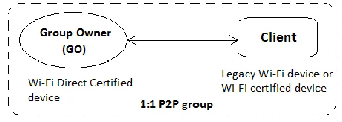
Figure 5: In a 1:1 P2P group, the GO has to be a Wi-Fi Direct smartphone while the client can be another Wi-Fi Direct supporting device or a legacy Wi-Fi certified
device. ... 28
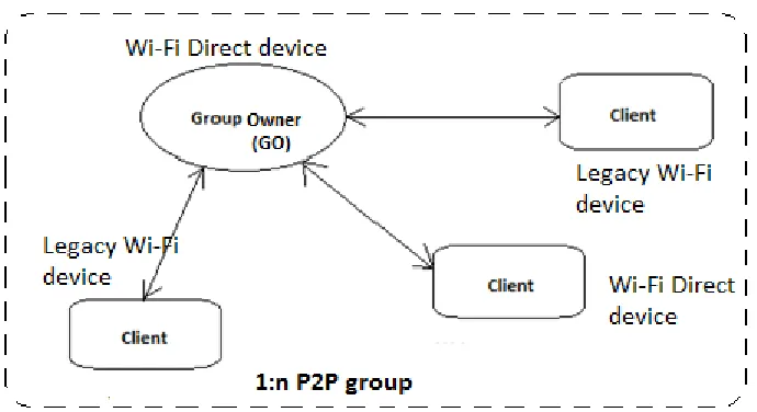
Figure 6: 1:n P2P group established between one GO and many clients. The GO serves as the AP of the P2P group. ... 29
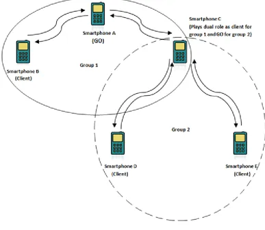
Figure 7: Smart phone C belongs to both group 1 and group 2 and alternates between being the client for group 1 and GO for group 2 ... 30
Figure 8: Overview of P2P group formation ... 31
10
Figure 10: WPS authentication process is completed and the GO assigns IP address
to its client. ... 35
Figure 11: DSRC timing diagram illustrating how safety messages are exchanged. 38 Figure 12: Wi-Fi Direct timing diagram illustrating safety message exchange between two vehicles. ... 39
Figure 13: Illustration of RTS/CTS three-way handshake. ... 42
Figure 14: RTS frame ... 43
Figure 15: CTS frame ... 43
Figure 16: ACK frame ... 44
Figure 17: Wi-Fi Direct transmission delay versus number of vehicles in a P2P group. As the number of vehicles increase in a P2P group, the transmission delay increases. ... 47
Figure 18: Transmission delay versus number of vehicles for DSRC... 49
Figure 19: Broadcast addressing scheme at network and data link layers. The broadcast address used at the network layer is 255:255:255:255 and at the data link layer FF:FF:FF:FF:FF:FF is used. ... 50
Figure 20: P2P transmission process using RTS/CTS method. ... 52
Figure 21: The graph shows the time delay for N number of vehicles in a group to exchange safety messages ... 54
Figure 22: Figure illustrates GO's of two smaller groups exchanging safety messages. ... 55
11
Figure 24: Graph illustarates the delay when K P2P groups of size N are exchanging safety messages. ... 58
Figure 25: Illustrates transmission delay versus P2P group size when exchanging safety messages between a vehicle and pedestrians. ... 61
List of Tables
Table 1: IEEE 802.11 standards. Taken from “Bluetooth and Wi-Fi wireless protocols: A survey and a comparison”, table 2 [28] ... 22
12
Chapter 1 Overview
With the rise in the number of vehicles being used over the years, there has been an
increase in the number of automobile accidents. As per the statistics provided by the
National Highway Traffic Safety Administration (NHTSA), 32,367 fatal vehicle
crashes occurred in 2011 [5]. The first quarter statistics for the year 2013 estimates
7200 deaths due to vehicle crashes [17]. These statistical values emphasize the need
to warn vehicle drivers of an impending collision.
Inter vehicular collision (IVC) [22] avoidance systems serve the purpose of
alleviating vehicle collision by constant exchange of safety related messages
between vehicles. Vehicles form small networks, which consist of moving vehicles
called Vehicular Ad-hoc Networks (VANET) [18]. VANETs form the framework for
vehicle communication and can support a range of applications, the most important
being safety related applications that will aid automobile drivers in preventing
accidents [19]. This form of communication between vehicles is called
Vehicle-to-Vehicle (V2V) Communication [21].
V2V communication has the potential to reduce the number of vehicular
accidents and improve driver’s safety. When data related to vehicle position, speed,
and heading is exchanged, the information is then used by each vehicle to calculate
whether the vehicle will collide with other vehicles and warn the driver to take
necessary actions to avoid a crash. This will provide knowledge to the vehicle
13
Information can also be exchanged between vehicles and infrastructure
known as Vehicle to Infrastructure (V2I) communication, which facilitates the
exchange of traveler’s information, tolling details, parking, emails and traffic
information.
Dedicated short-range communication or DSRC is a well-known technology
being considered to serve as a warning system. DSRC is a standard that exchanges
data pertaining to vehicle location and speed at fast transmission rates between
vehicles to prevent accidents [23]. DSRC technology supports both private and
public communications between vehicles. The Joint Program Office (ITS JPO) is
conducting intense research on DSRC at the U.S. Department of Transportation
(USDOT) Research Innovative Technology Administration (RITA). The U.S. DOT
focuses on reducing the number of accidents [10] [14] to provide a safer driving
environment to automobile users.
Numerous field trials have been conducted so far to test the DSRC system in
real time. In Ann Arbor, University of Michigan Transportation Research Institute
(UMTRI) is running a series of field tests called the Safety Pilot program to test
safety message exchange among DSRC vehicles and Vehicle to Infrastructure (V2I).
Based on the results collected, further decisions will be made by DOT regarding
DSRC deployment in vehicles [12].
Although DSRC is a promising technology, there are few concerns that need
to be addressed. DSRC equipment is installed in vehicles at an additional cost. The
14
an additional expense. Other concerns are related to exchange of both safety and
non-safety related messages. It is important that safety messages be given priority
and be exchanged efficiently in the presence of other non-safety messages. Another
gap in the technology is the inability to provide drivers with information related to
pedestrians, as they are not carrying DSRC transceiver equipment. Alternate
methods can be considered to provide warning messages to vehicle drivers. In this
work I will examine the feasibility of using Wi-Fi direct for communication between
vehicles and pedestrians carrying smartphones
Wi-Fi Direct is a new technology that is gaining recognition in the wireless
field. Wi-Fi Direct devices scan the communication channel for other Wi-Fi Direct
devices to form a Peer-to-Peer (P2P) group without an access point (AP). Legacy
Wi-Fi devices can be part of the P2P group as long as there is at least one Wi-Wi-Fi Direct
device in the group.
Wi-Fi Direct can be used for critical safety message exchange to avoid
inter-vehicular collision. With an increase in the number of smart phone users, Wi-Fi
Direct supported smart phones can be used for safety message exchange.
As Wi-Fi Direct is still in its nascent stage, there are gaps in the system that
need to be addressed. Messages sent over Wi-Fi Direct have more delay than the
messages sent over DSRC. Wi-Fi Direct uses 20MHz channel bandwidth when
compared to DSRC (10MHz) [33]. The larger delay is due to multiple
retransmissions by the group owner (GO). This limits the number of nodes in a P2P
15
In this thesis work, DSRC and Wi-Fi Direct transmission delays are calculated
and compared. Based on the results, a change in Wi-Fi Direct functioning is
proposed. Calculations are made to analyze if the proposed method can reduce the
transmission delay and increase the number of vehicles that can talk in a Wi-Fi
Direct group. This is challenging, as a Wi-Fi Direct group requires more message
traffic than DSRC. Next, a method is proposed to facilitate communication between
many groups of vehicles and calculations are then extended to determine the total
transmission delay between large numbers of groups, assuming they have the same
number of vehicles in each group. These results are used to illustrate the system
limitations. Also a few shortcomings of Wi-Fi Direct are recognized and possible
mitigation methods are proposed for future work.
Before we see how Wi-Fi Direct can be used for safety message exchange
between vehicles, we need to understand DSRC and it’s working. Chapter 2
illustrates the basic working of DSRC. In chapter 3 an overview of Wi-Fi is given that
provides the framework for Wi-Fi Direct technology. Chapter 4 introduces Wi-Fi
Direct and it’s working. Then in chapter 5, the change in Wi-Fi Direct architecture is
discussed and transmission delay calculations are made for DSRC and Wi-Fi Direct,
illustrating how the proposed method can reduce transmission delay. Also few
drawbacks and possible mitigation methods are discussed. The following chapter
16
Chapter 2 Dedicated Short Range Communication (DSRC)
2.1 Introduction
DSRC is a standard for the wireless exchange of safety and non-safety information
[24] between vehicles and between vehicles and infrastructure. DSRC transceivers
are installed in vehicles that allow them to talk to each other to exchange important
safety information. The safety system alert drivers in a timely manner about other
vehicles they are going to collide with, avoiding accidents.
DSRC system provides warnings to the drivers. Few of them are blind spot
warning, intersection warning, lane change warning, forward collision warning and
warnings when vehicle ahead brakes suddenly. Apart from exchanging safety
related warnings and information, DSRC can also be used for navigation assistance,
to collect traffic information, and to make parking, toll, or fuel payments [8].
DSRC is defined by IEEE 802.11p and IEEE P1609.x standards, which address
the transmission of information over radio link to provide safety services in a
vehicular environment. DSRC can transmit data at rates ranging from 3Mbps to
27Mbps [25].
2.2 DSRC bandwidth allocation
In the 5.9GHz spectrum, the Federal Communications Commission (FCC) allocated
75MHz bandwidth to be utilized by the Intelligent Transport System (ITS) for
development of safety applications in vehicles. The allocated 75MHz is to be used
17
exchange safety information. Non-safety related messages can be exchanged to
motivate use and development of DSRC systems [26] [8].
DSRC spectrum is divided into seven 10MHz channels as shown in figure 1,
where two channels can be combined for a larger bandwidth. The remaining 5 MHz
is reserved as the guard band [33]. All safety messages are transmitted on one
particular channel called the Control Channel (CCH) that corresponds to channel
number 178 in the United States. Of the remaining channels, channels 174, 176, 180
and 182 are referred to as the Service Channels (SCH) and can be used for both
safety and non-safety related messages. Channels 172 and 184 are for future
[image:18.612.115.494.370.425.2]development [26].
Figure 1: DSRC channel allotment showing the control channel and service channels
2.3 DSRC network components
For safety information to be exchanged in real time, DSRC equipment is required.
DSRC devices are transceivers capable of transmitting and receiving safety
messages. Vehicles have On Board Units (OBU) installed in them, which broadcast
Basic Safety Messages (BSM) [38] pertaining to the vehicle speed, heading and
current location. Equipment installed in infrastructure is known as Road Side Units
(RSU). RSU’s are immobile stations that maybe located on street signals and street
18
communication and communication between OBU and RSU is known as
vehicle-to-infrastructure (V2I) communication.
Each RSU forms an individual communication zone called the WAVE
(Wireless Access in Vehicular Environment) Basic Service Set (WBSS), and vehicles
move from one WBSS to another. At any given time, each vehicle is associated with
only one WBSS zone [11].
Figure 2 displays vehicles with OBUs that can communicate with other OBUs
and RSUs. DSRC equipment on the vehicle uses the received information and
compares it with the vehicles own information related to GPS (global positioning
system) location, speed and heading [27] to calculate if there is a collision threat.
Based on the calculated results, the DSRC equipment warns the vehicle driver to
19
Figure 2: Figure showing OBUs installed in vehicles and RSUs installed in street lamps.
2.4 Safety pilot program
The effectiveness of DSRC is being evaluated through ongoing research to test its
effectiveness in real time. The University of Michigan Transportation Research
Institute (UMTRI) is conducting one such research program, called the safety pilot
program.
UMTRI is working on the Safety Pilot program funded by the USDOT. The
program aims at deploying DSRC for V2V and V2I communication to test the
efficiency of the system in exchanging safety related information and check drivers
response in real time to these safety applications [13]. Vehicles of various sizes
20
where some vehicles come with inbuilt safety alert devices while the others use an
additional device all based on DSRC.
By using vehicles and drivers in real time, data will be collected to verify
safety system performance and to better understand its usage on a large-scale. The
collected results will be analyzed to support USDOTs goal to incorporate safety
systems as part of automobiles [12]. Upon collecting sufficient research data, the
results will be used to aid the National Highway Traffic Safety Administration’s
(NHTSA) decision on connected vehicles for safety [13].
Hence, we see that large scale DSRC deployment will take considerable time.
In the meantime, it is important that an alternate communication method be used
for exchanging safety information between vehicles like 3G, 4G, [41] LTE and Wi-Fi
Direct. Wi-Fi Direct is a new technology based on Wi-Fi. It is a new feature enabled
on some smartphones that can function in the absence of an Access Point (AP). By
installing safety applications on smartphones, critical safety information can be
exchanged with other smartphones using Wi-Fi Direct. To understand how vehicles
can talk using Wi-Fi Direct, we need to understand Wi-Fi Direct and it’s functioning,
which is explained in the next chapter.
21
Chapter 3 Wi-Fi
3.1 Background
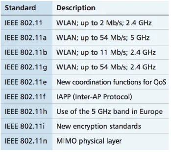
Wi-Fi or Wireless Fidelity is the IEEE 802.11 standard for connecting wireless devices
and setting up wireless local area networks (WLANS) [1]. The Wi-Fi IEEE 802.11
was approved back in 1997 to operate in the 2.4GHz bandwidth to support data
rates up to 2Mbps [28]. Ever since, IEEE 802.11 has been modified and upgraded to
support wireless connectivity between devices for faster data exchange.
The IEEE standard was modified and a new standard was released, IEEE
802.11b. This standard supports faster data rates of 11Mbps, operating in the
2.4GHz bandwidth. Around the same time, IEEE introduced 802.11a that uses 5GHz
bandwidth offering data transmission rates of 6, 9, 12, 18, 24, 36, 48 and 54Mbps.
The 802.11 further evolved to 802.11g, which operates in 2.4GHz bandwidth but
with performance characteristics of 802.11a [28]. IEEE 802.11 b/g is the commonly
used standard. IEEE 802.11b and IEEE 802.11g standards are backward compatible
as both operate at 2.4GHz bandwidth. With faster data rates offered by 802.11g,
both customers and manufacturers are migrating to the 802.11g standard. IEEE
introduced the 802.11n standard that offers larger transmission rates when
compared to the other 802.11 standards. It is more advanced than the previous
standards as it uses Multiple Input Multiple Output (MIMO) transmitter receivers
that provide spatial multiplexing [29]. Table 1 gives an overview of the 802.11
22
[image:23.612.131.480.70.382.2]
Table 1:IEEE 802.11 standards. Taken from “Bluetooth and Wi-Fi wireless protocols: A survey
and a comparison”, table 2 [28]
3.1.1 Operation
A Wi-Fi device, when turned on, scans for existing networks or devices with which it
can connect. Devices exchanging information via Wi-Fi operate in half duplex mode
[29]. These devices can connect to an ad-hoc or infrastructure mode network. When
connecting through infrastructure mode network, the Wi-Fi devices first associates
with an AP through which it connects to the remaining part of the network [28]. In
the wireless ad-hoc mode, the Wi-Fi enabled devices communicate directly without
23
networks when in motion. Upon discovering a new network, the Wi-Fi device
disconnects from the present network to connect to the new network.
[image:24.612.101.518.175.387.2]
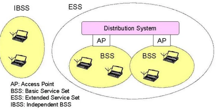
Figure 3: Basic Wi-Fi network, where two BSS are part of an ESS and are connected to each
other through the distribution system. Also seen is an IBSS. Taken from " A comparative study
of wireless protocols: Bluetooth, UWB, ZigBee, and Wi-Fi", figure 1 [1].
Wi-Fi has an architecture made up of cells. Each WLAN cell is called a Basic
Service Set (BSS) as shown in figure 3. BSS consists of stationary or mobile Wi-Fi
devices. If a device moves out of one BSS, it cannot communicate directly with the
remaining devices of that BSS. BSS can be part of a wider network consisting of
many BSSs. This larger network is called as the Extended Service Set (ESS). Multiple
BSSs are connected through the Distribution System (DS) in the ESS. The devices
connecting the DS play the role of an AP. This kind of network is the infrastructure
24
Set (IBSS) made of Wi-Fi devices that can exchange data in the absence of an AP. The
IBSS represents the ad-hoc mode networks [28].
Wi-Fi Direct is a new technology based on the IEEE 802.11n standard and
operates in the 5/2.4GHz bandwidth [33]. Wi-Fi Direct allows direct communication
between two devices without an AP but still maintains characteristics of an
infrastructure mode network by creating a soft AP [33][4].
Wi-Fi Direct is based on Wi-Fi technology with enhanced features. The next
chapter discusses Wi-Fi Direct working and architecture and its potential use in a
25
Chapter 4 Wi-Fi Direct
Wi-Fi Direct is an emerging technology that allows Wi-Fi Direct certified devices to
exchange information directly with each other, eliminating the need for an AP [4].
Devices are able to synchronize to share and view information by establishing P2P
connections.
Wi-Fi Direct opens new paths for inter-vehicular safety applications. A Wi-Fi
Direct application installed in smart phones of automobile drivers could exchange
important safety messages, same as a DSRC system, and warn drivers ahead of time
to prevent accidents.
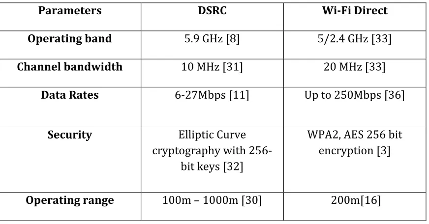
[image:26.612.86.522.467.695.2]4.1 Comparing DSRC and Wi-Fi Direct
Table 2 compares the characteristics of DSRC and Fi Direct Communications.
Wi-Fi Direct offers faster data rates over two-way area coverage and also supports
advanced security protocols to transmit data.
Parameters DSRC Wi-Fi Direct Operating band 5.9 GHz [8] 5/2.4 GHz [33]
Channel bandwidth 10 MHz [31] 20 MHz [33]
Data Rates 6-27Mbps [11] Up to 250Mbps [36]
Security Elliptic Curve cryptography with
256-bit keys [32]
WPA2, AES 256 bit encryption [3]
26
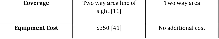
Coverage Two way area line of sight [11]
Two way area
[image:27.612.85.520.74.152.2]Equipment Cost $350 [41] No additional cost
Table 2: Comparison between DSRC and Wi-Fi Direct
4.2 Wi-Fi Direct in a vehicular environment
Some smartphones are Wi-Fi Direct certified devices. Drivers with smartphones
could install an application that uses the Wi-Fi direct capability of their phone to
exchange safety messages with other smartphones running the same application.
Once the smartphones are paired, safety messages are exchanged which can then be
used to determine an impending collision and alert the driver.
Wi-Fi Direct is a cost effective alternative to DSRC. DSRC requires dedicated
equipment to be installed in vehicles while Wi-Fi Direct software can be installed in
legacy Wi-Fi certified smartphones [4] at no additional cost.
Figure 4 shows vehicle 1, vehicle 2 and a pedestrian who is approaching the
street. The drivers of the vehicles are not aware of a pedestrian ahead walking
towards the road. By using Wi-Fi Direct on their smartphones, the vehicle drivers
and the pedestrian can exchange each other’s location information, to avoid
27
Figure 4: Illustrates how Wi-Fi Direct enabled smartphones can be used to exchange location
information between vehicle drivers and pedestrians to warn each other.
Smartphones use GPS for location information. The vehicles geographical
location is received on the smartphones GPS receiver from a GPS satellite [20]. The
location information along with other information (acceleration, braking, etc.) is
exchanged using Wi-Fi Direct.
In Wi-Fi Direct smartphones form P2P group and decide device roles as
clients and group owner (GO). Once the P2P group is established, data is exchanged
between the GO and the clients. The device roles and group formation process is
28
4.3 Architecture
Wi-Fi direct devices scan the 2.4 bandwidth and signal to devices with which they
can connect [3]. Once devices are found, pairing takes place and a P2P group is
established. For P2P group formation, at least one of the devices must support Wi-Fi
Direct and the remaining devices can be legacy Wi-Fi Certified devices [2]. Wi-Fi
devices are software upgradeable to support Wi-Fi Direct based on the
manufacturer [34].
4.3.1 P2P groups
Two types of P2P groups can be formed. First being a group of just two smartphones
as seen in figure 5. A second type of P2P group consists of one GO and many clients
as shown in figure 6 [3] [2], where all data transmissions occur through the GO. The
[image:29.612.137.472.446.566.2]GO acts as the AP in the P2P group through which all the clients communicate.
29
Figure 6: 1:n P2P group established between one GO and many clients. The GO serves as the AP of the P2P group.
Once a P2P group is formed, the GO beacons to announce the group’s
presence. Other clients can now connect to the group through the GO. It is important
to note that if the GO leaves the group, then the entire P2P group is brought down
and the group formation process repeats again. The role of the GO is not
automatically taken over by a successor in the group [4].
4.3.2 Concurrent operations by Wi-Fi Direct devices
In a Wi-Fi network all Wi-Fi devices connect to the AP and become part of the
WLAN. But Wi-Fi Direct smartphones can adorn dual roles of APs and clients. GOs
play the role of an AP in the P2P group. Wi-Fi Direct devices have the capability to
swap role functionality between being an AP of one group and client in another
group.
A Wi-Fi Direct device can be a client in one P2P group and GO in another P2P
30
group 1 and group 2. In group 1, smart phone C is a client. On the other hand,
smartphone C holds group 2 together by functioning as the GO. Information is
exchanged between group 2 clients via smartphone C for which smartphone C
[image:31.612.112.499.203.539.2]should support multiple MAC functionality [2].
Figure 7: Smart phone C belongs to both group 1 and group 2 and alternates between being the client for group 1 and GO for group 2
4.4 Group owner and client functionality
Every group that is formed has its own service set identifier (SSID) [3], which is the
31
authentication to the group members. The GO selects the operation channel for the
group from channels 1, 6 and 11 in 2.4GHz bandwidth [4]. It’s the GO’s
responsibility to provide the essential credentials for clients to join and function as
part of the group. The clients must be Wi-Fi certified devices and support Wi-Fi
Protected Setup [42] enrollee functionality [3]. WPS is the security mechanism
implemented within the P2P group [4].
4.5 Overview of P2P group
Before the P2P group is established the devices go through the device discovery
stage and GO negotiation stage as shown in figure 8. Once the P2P group is formed,
safety messages are exchanged between smartphones in the group.
[image:32.612.167.463.389.507.2]
Figure 8: Overview of P2P group formation
4.5.1 Device discovery stage
The smartphones scan the communication channels to detect devices with which
32
4.5.2 Group leader negotiation stage
After the smartphones discover devices and decide whom to connect to, the GO is
elected. The elected GO provides the group ID and the devices undergo WPS
authentication [3]. The GO acts as the DHCP server of the group and assigns IP
addresses to its clients [4].
4.5.3 Data transmission
Once the device roles and communication channel is selected, the devices in the P2P
group exchange safety information.
4.6 P2P group formation process
Figure 9 illustrates details of the P2P group formation process. We consider two
smartphones A and B that are Wi-Fi Direct certified and carried by two different
vehicle drivers.
1. Smartphone A and smartphone B actively scan for other smartphones in
their communication range in the non-overlapping channels 1, 6 and 11 [4].
2. Smartphones A and B send out probe requests on channels 1, 6 and 11
looking for devices with which they can pair in the search state. Probe
requests contain information pertaining to SSID, P2P Information Element
(IE), BSSID, WPS and destination address. The destination address can be a
particular smartphones IP address or a broadcast address [3].
3. The listen state is when the smartphone listens on one of the channels for
33
states for a random duration of 100ms to 300ms [4]. Smart phone A listens
on channel 11 while smart phone B listens on channel number 6.
4. From figure 9 when smartphone A is listening on channel 11, it hears probe
requests from smartphone B.
5. Smartphone A replies with a probe response frame. This completes the
device discovery process.
6. P2P connection can also be formed based on the services the connecting
devices desire. In this case, the smart phones are searching for other smart
phones to exchange safety related messages. Devices can be discovered
based on service requirements [35].
7. Once the devices find each other, the GO negotiation takes place and a GO is
elected based on number called the intent value. The device that has the
larger number is chosen as the GO. If both the devices have the same value
then the election is made based on a bit value set in the GO negotiation
request [4].
8. The elected GO then beacons out informing other devices of the group’s
presence. Other smartphones that hear the beacon respond if they want to
34
[image:35.612.161.492.75.428.2]
Figure 9: P2P group formation process where the smartphones scan channels 1, 6 and 11 to discover other devices.
9. The GO provides the group ID along with the authentication and encryption
credentials to the clients. Upon obtaining the essential credentials,
35
[image:36.612.149.449.81.269.2]
Figure 10: WPS authentication process is completed and the GO assigns IP address to its client.
10.After the authentication process the GO acts as the DHCP server and provides
IP address to its client as shown in figure 10.
Once a group is formed, the clients and the GO can exchange safety information.
4.7 Benefits of Wi-Fi Direct
Although a new technology, Wi-Fi Direct can be used as a communications means to
exchange safety messages. Without the need for additional hardware, legacy devices
can be upgraded by software to support Wi-Fi direct [34].
Wi-Fi direct supporting devices operate in 5 MHz band and offer speeds up to
100’s of Mbps which is comparatively much higher than 27 Mbps offered by DSRC.
Also Wi-Fi Direct devices are capable of operating as APs in a P2P group and at the
same time can belong to another P2P group as a client, supporting communication
36
The benefits of Wi-Fi Direct stretch out to pedestrians with Wi-Fi supporting
smartphones. Smartphones in vehicles can exchange safety information with
smartphones owned by pedestrians, providing location information of each other.
But there are some drawbacks to this new technology. Some of them being the high
initial group setup time, single point of failure for the group (GO) and large
transmission delay. This paper focuses on mitigating high transmission delay as
discussed in the following chapter.
Wi-Fi Direct is designed to establish P2P connections between the GOs and
clients. With the basic architecture, retransmission time increases with the rise in
number of clients joining the group. Safety message are exchanged between clients
through the GO. More time is spent by the GO in establishing a P2P connection and
retransmitting the BSM’s from clients to all other clients in the group.
The proposed method to mitigate the unnecessary retransmissions is by
having the GO use a broadcast mechanism instead of establishing P2P connections
with the clients. Now the GO broadcasts its own BSM along with the BSMs received
from all other clients in the group at once. This method saves the retransmission
37
Chapter 5 Evaluation of Wi-Fi Direct transmission delay
DSRC devices exchange safety messages by broadcasting BSM to all the other DSRC
devices in range. When using Wi-Fi Direct to exchange safety messages, all the
messages are exchanged through the GO. There is no direct communication between
the clients of the group. The following sections illustrate the timing diagrams of
DSRC and Wi-Fi Direct to describe critical safety information exchange between
vehicles.
5.1 DSRC timing diagram
Figure 11 depicts the timing diagram of DSRC. From the figure we see how the OBU
installed in the device receives information pertaining to GPS location of the vehicle,
information from the RSU and driver’s information like braking and acceleration.
This information is used along with the information received from other vehicles to
calculate whether an accident is imminent.
1. Information pertaining to vehicle A’s latitudinal and longitudinal location and
heading is gathered from the GPS and fed into the OBU installed in the
vehicle.
2. Driver A’s acceleration, braking and steering wheel angle information is fed
38
Figure 11: DSRC timing diagram illustrating how safety messages are exchanged.
3. Information from the RSU is received that provides information not visible to
the blind eye like traffic congestion, potholes in the road and weather.
4. The OBU uses the information received along with information it receives
from vehicle B and sends updates to the driver to take necessary action if a
collision is imminent.
39
5.2 Wi-Fi Direct timing diagram
Figure 12 illustrates Wi-Fi Direct timing diagram. The figure shows how safety
messages are exchanged between two vehicles, A and B that belong to the same P2P
[image:40.612.129.474.222.508.2]group.
Figure 12: Wi-Fi Direct timing diagram illustrating safety message exchange between two vehicles.
1. GPS gathered information pertaining to direction and location is used by the
safety application on smartphone A.
2. Similarly GPS gathered information pertaining to vehicle B’s heading and
40
3. Vehicle A sends its location and speed information to vehicle B using Wi-Fi
Direct.
4. Similarly vehicle B uses its location and speed information to vehicle A using
Wi-Fi Direct.
5. Smartphone A determines if a collision is imminent and warns the driver of
vehicle A.
6. Similarly smartphone B uses information received from vehicle A and
calculates if the two vehicles will collide and alerts the driver of vehicle B.
When a larger number of vehicles are considered, P2P communication is not as
convenient. As the group size increase the number of retransmissions through
the GO increases by N^2. The GO will hence waste its time in just retransmitting
safety messages as shown in section 5.4.1.
5.3 RTS/CTS process
For data communication within the P2P groups and between groups, IEEE 802.11
Carrier Sense Multiple Access (CSMA) / Collision Avoidance (CA) method is used. In
CSMA/CA, the wireless nodes compete for the wireless media access when no other
node is transmitting data. If the wireless media is busy then the nodes implement a
random back off algorithm after which they try to transmit again [6].
Distributed coordination function (DCF) [7] is the basic technique that uses
CSMA/CA to access the media. A random back off timer is counted to zero if the
wireless media is busy. After the timer expires the node tries to access the
41
If we have two clients A and B that are unaware of each other, trying to
communicate with the GO, A and B may transmit data at the same time creating
congestion in the network. This is known as the hidden node problem [43]. DCF
uses Request to Send (RTS) and Clear to Send (CTS) frames [6] prior to transmitting
data.
The GO and the clients use the RTS/CTS mechanism, a three-way handshake
process, before securing the communication media for exchanging information. The
source node sends an RTS frame to the destination that specifies the duration the
wireless media needs to be used for data transmission. If this is acceptable by the
destination, a CTS frame is sent in response. The actual data packet is then sent from
the source to the destination. Upon receiving the packet the destination sends an
acknowledge frame back to the destination.
The wireless media needs to be free for a period of DCF Inter-Frame Space
(DIFS) after which the source node transmits. Short Inter Frame Space (SIFS) is the
time duration to sense end of one frame and transmit next frame [7].
Figure 13 illustrates the RTS/CTS mechanism for exchanging safety messages
between smart phones in two different vehicles in an ad-hoc network.
1. Once the wireless media is determined to be free by the source vehicle for a
duration determined by DIFS interval, the source seeks permission to
transmit to the destination vehicle by sending a RTS frame.
2. The destination receiving this frame processes it and after an SIFS interval,
42
3. Upon receiving the CTS, the source now sends data as per the agreed window
size.
4. An acknowledgement (ACK) is sent back that tells the sender the data was
received by the destination and indicates the next frame the sender has to
send.
5. If the transmitter does not receive the ACK before a timeout period then the
frame is retransmitted.
[image:43.612.206.384.332.583.2]
43
6. When RTS and CTS are broadcasted other nodes must remain silent,
preventing them from transmitting at the same time. Hence, hidden node
problems can be solved.
5.3.1 RTS, CTS and ACK frame structure
For total transmission time calculations in the following sections the basic RTS, CTS
and ACK frames are used. Transmitter address is the address of the source device
and receiver address is the address of the destination device as shown in figures 14
and 15.
In the RTS frame, duration indicates the time required to transmit the next
frames [37]. Duration in the CTS frame is time required to transmit the CTS frame
and SIFS associated with CTS. While duration in the ACK frame provides the time
required to transmit the ACK frame and SIFS interval [37].
[image:44.612.145.468.480.554.2]1. Request to send (RTS) frame
Figure 14: RTS frame
2. Clear to send (CTS) frame
44
[image:45.612.195.457.102.173.2]3. Acknowledgement (ACK) frame
Figure 16: ACK frame
5.4 Transmission delay calculations
The number of iterations the GO undergoes for retransmitting safety messages in
the general Wi-Fi Direct mechanism is high, due to the P2P group architecture. As
the number of vehicles increase, more time is spent in just retransmitting BSMs to
the clients by the GO.
The transmission delay is calculated as shown:
Transmission delay = [Total data (bytes) * 8 bits]/ Transmission rate
Considering, a basic safety message that is 50 bytes in length, transmitted at a rate
of 6Mbps we calculate the transmission delays for Wi-Fi Direct and DSRC assuming
there is no data loss.
5.4.1 Transmission delay calculations for General Wi-Fi Direct
The ideal transmission delay calculations for a Wi-Fi Direct group using
point-to-point connections are shown below.
We assume,
45
CTS frame size = 14 bytes
ACK frame size = 14 bytes
DIFS interval = 50µs
SIFS interval = 10µs
The time required to transmit the RTS, CTS, BSM and ACK frames are calculated as
shown:
RTS_time = (RTS frame * 8 bits) / (Transmit rate)
= (20 bytes * 8 bits) / (6 * 10^6)
= 26.66µs
CTS_time = (CTS frame * 8 bits) / (Transmit rate)
= (14 bytes * 8 bits) / (6 * 10^6)
= 18.66µs
BSM_time = (BSM * 8 bits) / (Transmit rate)
= (50 bytes * 8 bits) / (6 * 10^6)
= 66.66µs
ACK_time = (ACK frame * 8 bits) / (Transmit rate)
= (14 bytes * 8 bits) / (6 * 10^6)
46
The total delay to send a BSM by the GO to a single client is calculated as follows:
Total delay for BSM transmission by one device = (DIFS + RTS_time + SIFS
+ CTS_time + SIFS + BSM_time + SIFS + ACK_time)
= (50 + 26.66 + 10 + 18.66 + 10 + 66.66 + 10 + 18.66) µs
= 210.64µs ……… (i)
For a group of N vehicles, the time taken by the GO to transmit its BSM one at a time
to each client is given by:
Delay (TGO) = (N-1) * 210.64µs
Similarly the clients of each group transmit their BSM to the GO one at a time:
Delay (TClients) = (N-1) * 210.64µs
Now the GO retransmits the BSM received from N-1 clients to the remaining N-2
clients of the group:
Delay (TGO retransmission) = (N-1)*(N-2) * 210.64µs
The total transmission delay for Wi-Fi Direct is expressed as:
Total delay (Wi-Fi Direct) = Delay (TGO) + Delay (TClients) + Delay (TGO retransmission)
Figure 17 shows the plot of N number of vehicles in a P2P group versus
transmission delay. As the group size increases the retransmissions within the P2P
group increase. For inter-vehicular safety applications, it has been suggested to
47
Figure 17: Wi-Fi Direct transmission delay versus number of vehicles in a P2P group. As the number of vehicles increase in a P2P group, the transmission delay increases.
For Wi-Fi Direct the transmission delay is 106ms for 23 vehicles and 97.3ms
for 22 vehicles. This indicates that with 22 vehicles in a group the delay reaches
100ms. Hence the group size has to be restricted to a maximum of 22 vehicles for
exchanging critical safety information.
5.4.2 Transmission delay calculations for DSRC
Consider N vehicles within the DSRC communication range exchanging safety
messages with each other. We assume that all nodes stop and listen to the data
48
The first vehicle sends out its BSM after waiting for a DIFS interval of 64 µs[44].
Similarly each of the N nodes transmits its BSM:
N*BSM
All N nodes immediately receive the broadcast, so no retransmission is required.
Therefore,
The delay when transmitting BSM from one vehicle is expressed as:
Delay (One vehicle) = DIFS + [BSM (bytes) * 8 bits] / [Transmit rate] For N vehicles the total delay is:
Total delay = Delay (One vehicle) * N
From figure 18 we can see that the total transmission delay is lower for DSRC
when compared to Wi-Fi Direct. For 22 vehicles the transmission delay was 97.3ms
while DSRC can serve 767 vehicles to reach the 100ms thresh hold. Hence, we see
that as the group size increases in Wi-Fi Direct, the GO spends most of its time just
49
Figure 18: Transmission delay versus number of vehicles for DSRC.
To reduce this delay a change in Wi-Fi Direct functioning is proposed. By
implementing broadcast mechanism for the GO alone, the numerous
retransmissions are eliminated and a single transmission is made from the GO,
reducing transmission delay as discussed in the next section.
5.5 Proposed model
Time delay is very crucial in collision avoidance systems. The basic architecture of
Wi-Fi Direct needs to be modified to serve the purpose of transmitting safety
messages fast and reliably among moving vehicles. Instead of P2P connections from
50
messages to all the clients in the group, eliminating the retransmission time. With
the new model we see that the transmission delay can be reduced and more vehicles
can talk within the P2P group.
5.5.1 Broadcast mechanism used by the GO
Wireless broadcast is the process by which the information packet transmitted by
the source is received by all nodes on the same network. Special addresses are used
in the destination fields of the frame and packet. Destination address in the frame is
represented by all F’s as FF:FF:FF:FF:FF:FF and the source MAC address is the
address of the sender. The destination IP address is represented by all 255s and the
[image:51.612.130.504.386.576.2]source IP address belongs to the source node.
Figure 19: Broadcast addressing scheme at network and data link layers. The broadcast address used at the network layer is 255:255:255:255 and at the data link layer
FF:FF:FF:FF:FF:FF is used.
In figure 19 the GO is broadcasting a packet to both its clients. The clients
51
message the destination IP is represented by 255.255.255.255. Similarly the
destination MAC address is represented as all F’s.
When the safety message is broadcasted on the wireless media by the GO, the
clients receive this broadcasted message and check for the destination addresses.
Since the MAC address is represented by FF:FF:FF:FF:FF:FF both the clients receive
the frame and the frame is de-encapsulated and sent to the network layer. The
network layer checks the destinations IP address, which is represented by 255.
Since both the clients receive the packet and the safety information in the data is
used by the safety application on the smart phone to calculate the positions of other
vehicles.
5.5.2 Transmission delay calculations using broadcast mechanism
In this section we calculate the total data transmission delay using CSMA/CA. It is
important to note that these calculations are made for best-case scenario assuming
there is no contention for the communication media. The resulting values are not
realistic and only help analyze the Wi-Fi Direct system.
Using equation (i) the total time required to send a BSM by a client to the GO is:
Total delay for BSM transmission by one client = 210.64µs
For a group of N vehicles, the time taken by all the clients to transmit their BSM’s
one at a time to the GO is given by:
52
Now the GO broadcasts a large message with all the BSMs received from the clients
in the group back to the clients. By broadcasting the entire BSM, the GO eliminates
redundant retransmissions that the original Wi-Fi Direct system had.
Total broadcasted BSM = N * BSM
[image:53.612.215.383.243.606.2]
53
When the total BSM is broadcasted by the GO, RTS/CTS signals are not used. The GO
waits for a DIFS interval and then broadcasts. Time taken by the GO to broadcast the
total BSM back to the clients is expressed as:
GO broadcast delay (TGO)=DIFS+(total broadcasted BSM * 8)/(Transmit rate)
…… (iii)
Hence,
Total delay is represented as Ttotal for N vehicles in a group to exchange safety
critical information is:
Total time (Ttotal) = (TC) + (TGO) …….. (iv)
From the plot shown in figure 21 we notice that if the number of vehicles
increases beyond 363 in one group then the delay exceeds 100ms. To minimize the
delay in exchanging safety critical information within a group, the number of
54
Figure 21: The graph shows the time delay for N number of vehicles in a group to exchange safety messages
5.6 Communication between two groups of vehicles
As we limit the size of the groups it is important that the GOs of each group can
exchange safety critical information between their group and another group of
vehicles. The GOs again use broadcast mechanism to exchange group information.
From figure 22 we see two groups, of four vehicles each and the GOs talk to each
55
Figure 22: Figure illustrates GO's of two smaller groups exchanging safety messages.
5.6.1 Timing diagram for safety message exchange between GOs
The timing diagram shown in figure 23 illustrates safety messages being exchanged
between two GOs. We assume group 1 and group 2 are using channel 6 for
exchanging safety messages within their group. The GOs use channel 11 to
56
Figure 23: Timing diagram showing safety message being exchanged between GOs of two groups.
1. Group 1 clients exchange BSM with their GO one at a time on channel 6.
2. Group 2 clients similarly exchange BSM with GO 2 on channel 6.
3. GO 1 broadcasts the total BSM back to its clients. Now the clients are aware
of all the group member locations.
4. Similarly GO 2 broadcasts the total BSM to all its clients and the clients
update themselves with positions of the other group members.
5. The two GO’s listen on channel 11 and broadcast their total BSM.
6. The received BSM is sent to group 1 clients by GO 1.
57
5.7 Transmission delay while exchanging safety messages between vehicles in a group and among group leaders
Assuming that the drivers of all the vehicles are using smartphones that support
Wi-Fi Direct, we calculate the time delay to exchange safety information between
varying numbers of groups when the number of vehicles in each group is the same.
N = Number of vehicles in each group
K = Number of GOs exchanging safety messages
Let us consider K groups and N as the number of vehicles in each group. The group
leaders talk with their clients on channel 6 while safety messages between the GOs
are exchanged on channel 11.
Assuming that there is no packet loss due to interference between members of
different groups and within the same group, transmission delay to exchange safety
information between all groups is calculated as follows:
Using equations (ii), (iii) and (iii) from section 5.6 we know the delay for safety
information exchange within one group is (T).
Total time (Ttotal) = (TC) + (TGO)
The time taken by one GO to send out its total BSM on channel 11 can be expressed
as:
58
Time taken to exchange total BSMs between all GOs
(Tk) =K * (DIFS + (N * BSM * 8) / (Transmit rate)
Now the BSMs received from all other GOs is transmitted back into its own group
and the time required to complete this is represented as,
Tgroup = DIFS + (K * N * BSM *8) / (Transmit rate)
Hence,
The total delay when safety messages are exchanged between groups of same size is
expressed as
[image:59.612.90.524.361.664.2]Total time = Ttotal + Tk + Tgroup
Figure 24: Graph illustarates the delay when K P2P groups of size N are exchanging safety messages. 0 0.02 0.04 0.06 0.08 0.1 0.12
1 3 5 7 9 11 13 15 17 19 21 23 25 27 29 31 33 35 37 39 41 43 45 47 49
Tot
al
Time (
se
cond
s
)Number of vehicles in each group (N)
59
Figure 24 illustrates the total delay for BSM transmission when using Wi-Fi
Direct for 13 P2P groups. For 13 P2P groups of size 49 vehicles, the delay is 100ms.
We can have small groups communicating with each other or we can increase the
group size and limit the number of large groups exchanging safety information.
5.8 Safety message exchange between pedestrians and vehicles
So far we have seen how drivers using smartphones can exchange safety messages
over Fi Direct. Safety applications are also available to pedestrians carrying
Wi-Fi enabled smartphones. Pedestrian location and heading information is exchanged
with smartphones of vehicle drivers and other pedestrians. Now the clients of the
P2P are aware of both other vehicles and pedestrians in the surrounding.
Wi-Fi Direct enabled smart phones can exchange safety messages between
vehicles, pedestrians and even bicycle users. Location information received from
vehicle drivers can warn pedestrians and bicyclists of approaching vehicles.
Similarly automobile drivers can be warned of pedestrians and bicyclists suddenly
entering the roads. Safety applications using Wi-Fi Direct can be delivered to
pedestrians without the need to carry additional devices.
Smart phones of pedestrians can join existing P2P groups to exchange basic
location and direction information. Let us consider 16 bytes of BSM being exchanged
between pedestrians and vehicle drivers at 6Mbps. The BSM exchanged contains
60
above sea level, message ID and heading [8] when compared to the 50 bytes of BSM
exchanged among vehicles.
5.8.1 Transmission delay calculations between vehicles and pedestrians
Let us assume safety messages are exchanged between a smartphone in a vehicle
and smartphones of pedestrians. The smartphone in the vehicle plays the role of the
GO.
BSM = 16bytes
Data transmission rate = 6Mbps
Smart phones used by pedestrians and bicyclists can join existing P2P groups as
clients to receive safety alerts.
The P2P GO broadcasts its own BSM to N-1 clients:
BSM*(N-1)
The GO then receives BSM from N-1 clients in the group:
BSM*(N-1)
GO retransmits the total BSM to the remaining N-2 clients:
BSM*(N-2)*(N-1)
The total traffic within the group is expressed as:
61
Therefore,
Transmission delay (Pedestrians) = [Total BSM (bytes)(Pedestrians) * 8 bits]/[data
transmission rate (bps)]
From figure 25 shows a plot of transmission delay versus P2P group size
when exchanging basic safety information in a P2P group formed by a vehicle and
pedestrians. Since the BSM exchanged within the group is 16bytes, the transmission
delay is 100ms for a group of 68 nodes. When the group size is 98, the transmission
[image:62.612.93.518.331.667.2]delay is 200ms.
62
5.9 Drawbacks and suggested mitigation methods
To successfully deploy Wi-Fi Direct as a time sensitive collision avoidance system
the gaps in the technology need to be addressed to increase system efficiency for
better performance.
One of the major concerns apart from large retransmission time is the initial
setup time incurred to form the Wi-Fi Direct group and the authentication phase.
The initial setup time consists of two parts, the group discovery phase and group
formation phase. Discovery phase is when the Wi-Fi Direct devices scan for other
Wi-Fi Direct devices or legacy Wi-Fi Devices to which they can connect. And the
group formation starts once the devices discover each other and are paired to form
a Wi-Fi direct group. The total time taken to complete this process is approximately
15 seconds [3]. This is a very large set up time. This poses a problem for time
sensitive applications. If the device discovery and authentication during group
formation can be completed faster, then time can be saved.
Once a group is formed, data exchange is through the GO. If the GO leaves the
group or connectivity is lost to the GO, the group is torn down and connectivity is
lost between all clients of the group. Now the clients start scanning channels 1, 6
and 11 for other Wi-Fi Direct groups or other devices with which a group can be
formed. The entire process is reinitiated. This problem can be overcome if a backup
GO is elected along with the main GO when a group is formed. If connectivity is lost
63
safety messages will be exchanged through the GO. This saves on the group
formation time.
Another concern with respect to the P2P group is the awareness the
smartphones have of other members in the group. If a client leaves the group there
is no immediate way the GO is informed of the client’s absence. One possible
solution is that the GO can attempt to communicate to a particular client a few times
64
Chapter 6 Conclusions and future work
Vehicle-to-vehicle communication promises a safer driving environment. The U.S
Department of Transportation (USDOT) has decided to deploy safety systems in
lightweight vehicles to exchange information including location, heading, and speed
of the vehicles [40]. The safety systems are designed to provide warnings to drivers
so that necessary actions are taken to prevent accidents.
As discussed in this work, DSRC technology is designed to exchange safety
information in a vehicular environment. Wi-Fi Direct can be used as an alternate
method to DSRC for exchanging safety messages. This paper introduced us to Wi-Fi
Direct, which is a P2P half duplex system operating in the 2.4GHz/5GHz bandwidth
and can provide transmission speeds up to 802.11n.
DSRC technology was described and then Wi-Fi Direct was introduced. The
transmission delay was calculated for the Wi-Fi Direct and DSRC systems. The
results proved that the delay was high in case of the case of Wi-Fi Direct due to BSM
retransmissions by the GO causing unnecessary congestion in the network. As an
effort to reduce the delay, a broadcast mechanism for the GO was proposed and
transmission delay was calculated for the proposed model. The results showed an
improvement in transmission delay when compared to the basic Wi-Fi Direct
architecture. To maintain a low delay, the group size should be limited and a new
communication method between groups is proposed. Finally transmission delay is
65
Several gaps in Wi-Fi Direct technology need to be addressed in the future.
Most important being the large setup time. If methods to reduce the total setup time
can be implemented then the system performance increases and safety messages
will be transmitted quicker than before. Another challenge is to avoid the group
formation process if the GO leaves the group or connectivity is lost to it. Instead, if a
back up GO is chosen along with the group leader then after a period of absence of
66
List of Acronyms
AP Access point
BSM Basic Safety Message
BSS Basic Service Set
CCH Control Channels
CSMA/CA Carrier sense multiple access with collision avoidance
CTS Clear to send
DCF Distributed coordination function
DIFS DCF inter frame space
DHCP Dynamic host configuration protocol
DSRC Dedicated Short Range Communications
ESS Extended Service Set
FCC Federal Communications Commission
GPS Global Positioning System
IBSS Independent Basic Service Set
IE Information element
ITS Intelligent Transportation System
MIMO Multiple Input Multiple Output
NHTSA National Highway Traffic Safety Administration
OBU On Board Units
67
RITA US Department of Transportation Research and Innovative
Technology Administration
RTS Request to send
SCH Service Channels
SIFS Short inter frame space
SSID Service Set Identifier
UMTRI University of Michigan Transportation Research Institute
USDOT United States Department of Transportation
V2V Vehicle to vehicle
V2I Vehicle to infrastructure