Iowa State University Patents
Iowa State University Research Foundation, Inc.
6-22-2004
Method and apparatus for bone sensing
Peter V. Boesen
John A. Roberts
Iowa State University
David S. Whitty
Follow this and additional works at:
http://lib.dr.iastate.edu/patents
Part of the
Biomechanical Engineering Commons
, and the
Medicine and Health Sciences
Commons
This Patent is brought to you for free and open access by the Iowa State University Research Foundation, Inc. at Iowa State University Digital Repository. It has been accepted for inclusion in Iowa State University Patents by an authorized administrator of Iowa State University Digital Repository. For more information, please [email protected].
Recommended Citation
Boesen, Peter V.; Roberts, John A.; and Whitty, David S., "Method and apparatus for bone sensing" (2004).Iowa State University Patents. 183.
Method and apparatus for bone sensing
Abstract
The invention discloses an improved bone conduction sensor capable of use within a voice sound transmitting
apparatus. The bone conduction sensor is adapted for placement in the external auditory canal of the user in a
nonocclusive fashion. The bone conduction sensor has a contoured surface adapted-to fit against a wall of the
external auditory canal increasing the surface area contact between the bone conduction sensor and the wall
of the external auditory canal. The bone conduction sensor may also be associated with one or more contact
sensors adjacent the bone conduction sensor for determining contact between the bone conduction sensor
and the wall of the external auditory canal. In addition, the invention provides for the bone sensing element to
be separated from the circuit portion of the bone conduction sensor so that the circuitry may be removed to
the behind the ear portion of the earpiece.
Keywords
Mechanical Engineering
Disciplines
Biomechanical Engineering | Mechanical Engineering | Medicine and Health Sciences
US006754358B1
(12) United States Patent
(10) Patent N0.:
US 6,754,358 B1
Boesen et al.
(45) Date of Patent:
Jun. 22, 2004
(54) METHOD AND APPARATUS FOR BONE OTHER PUBLICATIONS
SE SI G
N N Article entitled “One—SiZe Disposable Hearing Aid is Intro (76) Inventors, Peter V_ Boesen, 1000 73rd St, Suite duced,” Wayne J. Staab, Walter Sjursen, David Preves &
18, Des Moines, IA (US) 50311; John
Ton} Squegha, P- 3641,51“ 2000;
A_ Roberts, 56284 HWY 210, Huxley,
Article entitled “The Hearing Review”, Jan. 1999, vol. 3,
IA (Us) 50124; David S_ Whmy, 1009 Hearing in Noise (Supplement), pp. 1—62.
NE Grant St APL 204 Ankeny IA Article entitled, “5th International Conference on Wearable (Us) 50021 ’ ’ ’ Computers,” by Rick Johnson, Pen Computing Magazine,
Aug. 2000.
( * ) Notice: Subject to any disclaimer, the term of this Air Magic Wireless Headset User Guide
patent is extended or adjusted under 35 Article entitled, “Agilent Technologies Announces Avail U_S_C_ 154(k)) by 0 days_ ability of Wireless Network Cap for Portable Patient Moni
tor,”
http://WWW.healthcare.agilent.com/press—re;ease/
_ PRHS2920030.html.
(21) Appl' NO" 09/902,153
Article entitled, “Agilent Technologies Introduces NeW
(22) Filed:
Jul. 10, 2001
Telemon Patient Monitor,” http:/WWW.healthcare.agilent.
com/press—release/PRHS2920016.html.
Related US. Application Data
(List continued on next page.)
63 Continuation-in- art of a lication No. 09/587,743, ?led on _ _ .
( ) Jun. 5, 2000, which is gpcontinuation of application No.
P
r lmar
y Exammer—cu_rns KuntZ
09/309,107, ?led on May 10, 1999, now Pat. No. 6,094,492. Assistant Examiner—D10nne Harvey
(74) Attorney, Agent, or Firm—McKee, Voorhees & Sease,
(51) Int. Cl.7 ... .. H04R 25/20 P-L-C
U-S
... .. 381/312; 381/380; 381/324; 381/173
(58) Field of Search ... .. 600/528, 529, The invention discloses an improved bone conduction sen
600/536; 607/27, 62; 381/313, 312, 322, sor capable of use Within a voice sound transmitting appa 324, 326, 328, 114, 151, 329, 162, 380, ratus. The bone conduction sensor is adapted for placement 361, 173; 340/8532, 426.24, 463, 539.22, in the external auditory canal of the user in a nonocclusive
539.23, 545.2, 391.1 fashion. The bone conduction sensor has a contoured surface
adapted-to ?t against a Wall of the external auditory canal
(56) References Cited increasing the surface area contact betWeen the bone con
US' PATENT DOCUMENTS
drltllction sensor and the Wall of the external auditory'canal.
e bone conduction sensor may also be associated With one
4,150,262 A 4/1979 Ono or more contact sensors adjacent the bone conduction sensor
4,334,315 A 6/1982 Ono et al. for determining contact betWeen the bone conduction sensor
4,588,867 A 5/ 1986 Konomi and the Wall of the external auditory canal. In addition, the
invention provides for the bone sensing element to be separated from the circuit portion of the bone conduction
FOREIGN PATENT DOCUMENTS sensor so that the circuitry may be removed to the behind the
ear portion of the earpiece. (List continued on next page.)
EP 0 683 621 A 11/1995
GB 2 074 817 11/1981
JP 2000022670 A 1/2000 12 Claims, 6 Drawing Sheets
F14
22
r12
AIR BONE
CONTACT
CONDUCTION CONDUCTION
SENSOR SENSOR SENSOR
16
—|
[-28
If ____ __.'_;I_V_E_R ______________________ T'
ETRANSC
iK34
i
TRANSMITTER
RECEIVER
I
US 6,754,358 B1
Page 2
US. PATENT DOCUMENTS 4,654,883 A 3/1987 Iwata
4,791,673 A 12/1988 Schreiber
5,033,090 A * 7/1991 Weinrich
5,191,602 A 3/1993 Regen et al. 5,201,007 A 4/1993 Ward et al. 5,280,524 A 1/1994 Norris
5,295,193 A * 3/1994 Ono
5,298,692 A 3/1994 Ikeda et al. 5,381,798 A 1/1995 Burrows 5,417,222 A 5/1995 Dempsey et al. 5,422,934 A 6/1995 Massa
5,458,123 A 10/1995 Unger
5,613,222 A 3/1997 Guenther 5,692,059 A * 11/1997 Kruger 5,721,783 A 2/1998 Anderson 5,771,438 A 6/1998 Palermo et al. 5,803,915 A * 9/1998 Kremenchugsky 5,933,506 A 8/1999 Aoki et al.
5,959,896 A * 9/1999 Forbes
5,987,146 A 11/1999 Pluvingage et al. 6,021,207 A 2/2000 Puthuff et 211.
6,094,492 A * 7/2000 Boesen
6,112,103 A 8/2000 Puthuff 6,181,801 B1 1/2001 Puthuff et 211.
OTHER PUBLICATIONS
Article entitled, “Brain cancer victirn sues cell—phone pro
viders,”
http://WWW.cnn.corn/2000/TECH/cornputing/08/
08/cellular.cancer.laWsuit.idg/indexhtrnl, Aug. 8, 2000.
Article entitled, “M3 and M4 Series Patient Monitors,”
http://WWW.healthcare.agilent/corn/shoWiproductpl?M3%
20and20M4%20Series%20Patient%20rnonitor.
Article entitled, “Report Urges Curbs on Mobile Phone Use,” http://WWW.tyechWeb.corn/Wire/story/ l WB2000515 S005: May 15, 2000.
Article entitled, “Scientist link eye cancer to mobile
phones,” by Jonathan Leakes: Jan. 14, 2001: http://WWW.
Sunday—tirne.co.uk/neWs/pages/sti/2001/01/14/
stinWensW01032.htrnl.
Article entitled, “The latest on cell phone ernissions”. Article entitled “U.S. Will Oversee Cell—Phone Safety Stud
ies,”
http://WWW.techWeb.corn/Wire/story/reuters/REU
20000609S0003 Jun. 9, 2000.
Article entitled “What is a Wireless LAN ?,” 1998, ProXirn,
Inc.
Article entitled, “Wireless Worries Are Cell Phones a Dan ger to You and Your Children,” http://rnore.abcneWs.go.
corn/onair/2020/2020i00526icellphones.htrnl May 26,
2000.
Bluetooth Usage Model, http://WWW.bluetooth.corn/blue
toothguide/rnodels/ultirnate.asp (visited Jun. 26, 2000).
U.S. Patent
Jun. 22,2004
Sheet 1 0f 6
US 6,754,358 B1
12
16
U.S. Patent
Jun. 22, 2004
Sheet 3 0f 6
US 6,754,358 B1
Fig. 3A
(PRIOR ART)
[image:7.614.134.477.66.717.2]U.S. Patent
Jun. 22, 2004
Sheet 4 0f 6
US 6,754,358 B1
22b
2
22a
Fig. 4A
1
22b
12
22a
1
Fig. 45
22b
2
22a
Fig. 4C
22
12
[image:8.614.171.428.68.732.2]US 6,754,358 B1
1
METHOD AND APPARATUS FOR BONE SENSING
CROSS-REFERENCE TO RELATED APPLICATIONS
This application is a continuation-in-part to U. S. patent
application Ser. No. 09/587,743 ?led Jun. 5, 2000, Which is
a continuation of U. S. patent application Ser. No. 09/309, 107 ?led May 10, 1999 and issued as U. S. Pat. No. 6,094,492 on Jul. 25, 2000.
BACKGROUND OF THE INVENTION
1. Field Of The Invention
The present invention is a method and apparatus for bone
sensing in a voice sound transmitting apparatus and system.
2. Problems In The Art
The present invention relates to improvements in bone conduction sensing particularly as they relate to use in a
voice sound transmitting apparatus. Avoice sound transmit
ting apparatus is disclosed in U. S. Pat. No. 6,094,492 to Dr.
Peter V. Boesen, M.D. herein incorporated by reference in its entirety. To improve upon the voice quality, both a bone
conduction sensor and an air conduction sensor are used. Processing can occur on the bone conduction sensor sensed
signal and the air conduction sensor sensed signal in order to better determine the voice sound information and in order
to block out ambient noise or other extraneous information
that might be undesirable. The voice sound transmitting
apparatus of Boesen places the bone conduction sensor
Within the external auditory canal of a user in a manner that
is nonocclusive.
Despite these advancements and advantages, problems
remain.In particular, prior art bone conduction sensors have a
number of characteristics and limitations that limit their performance in the context of a voice sound transmitting apparatus. First, it should be apparent that a number of bone
conduction sensors are dimensioned in a manner that pre
cludes their use in a bone conduction sensing apparatus that
?ts Within the external auditory canal of a user. This is
particularly true Where the placement of the bone conduction
sensor in an external auditory canal is nonocclusive. Where
nonocclusivity is sought, reduced dimensions are preferred.
A further problem With prior art bone conduction sensors is the shape of the sensor. The Applicants have found that in
order to improve bone conduction sensing the bone conduc
tion sensor should be shaped in a manner that improves the ?t of the bone conduction sensor to the Wall of the external
auditory canal in order to increase the surface area of the
bone conduction sensor that contacts the Wall of the external
auditory canal. Therefore, there are problems With the shape
of current bone conduction sensors.
A further problem identi?ed by the Applicants is the
tendency of an earpiece containing a bone conduction sensor positioned in the external auditory canal to be displaced or
dislodged over time. This degrades the quality of sound received from the voice sound transmitting apparatus.
Thus, there are a number of needs not currently being addressed related to bone conduction sensing in a voice
sound transmitting apparatus.
Therefore, it is a primary object, feature, or advantage of
the present invention to provide an apparatus and method Which improves upon the state of the art.
It is another object, feature, or advantage of the present
invention to provide an apparatus and method for bone
conduction sensing.
10 15 20 25 30 35 40 45 50 55 60 652
It is a further object, feature, or advantage of the present invention to provide an apparatus and method for bone conduction sensing suitable for use in the external auditory canal.
It is a further object, feature, or advantage of the present invention to provide an apparatus and method for bone
conduction sensing Within the external auditory canal that is
nonocclusive.
As a further object, feature, or advantage of the present invention to provide an apparatus and method for bone
conduction sensing that is capable of detecting When the
bone conduction sensor has been displaced.
Yet a further object, feature, or advantage of the present invention is to provide an apparatus and method for bone conduction sensing that provides for increased surface area
contact.
A still further object, feature, or advantage of the present
invention is to provide an apparatus and method for bone conduction sensing that is small in siZe.
Another object, feature, or advantage of the present
invention is to provide an apparatus and method for bone
conduction sensing that provides for improved sensor place
ment Within an ear.
A further object, feature, or advantage of the present
invention is to provide an improved apparatus and method
for bone conduction sensing suitable for use in a voice sound
transmitting apparatus.
A still further object, feature, or advantage of the present invention is an improved voice sound apparatus capable of
compensating for a displaced bone conduction sensor.
These and other objects, features, or advantages of the present invention Will become apparent from the speci?ca
tion and claims.
BRIEF SUMMARY OF THE INVENTION
The present invention is an apparatus and method for
improved bone conduction sensing. The present invention
includes an improved bone conduction sensor that is siZed
and shaped to nonocclusively ?t Within the external auditory
canal of a user. The bone conduction sensor is further shaped to increase the surface area contact betWeen the external
auditory canal Wall and the bone conduction sensor. Acircuit portion of the bone conduction sensor is positioned at a location remote from the bone conduction sensing element in order to reduce the siZe of the portion of the bone conduction sensor placed Within the external auditory canal.
The bone conduction sensor also includes one or more
contact sensors adjacent to the bone conduction sensor used to determine Whether the bone conduction sensor is in
contact With the external auditory canal of the user. Further,
the present invention provides for a separation layer that
may be attached betWeen the bone conduction sensor and the
external auditory canal in order to improve the sensing performance and to protect the Wall of the external auditory
canal.
The present invention includes an improved voice sound
transmitting apparatus that uses the bone conduction sensor
of the present invention. The bone conduction sensor is
combined With an air conduction sensor placed Within the
external auditory canal of the user. Additionally, the earpiece
can include a speaker, a processor, and a transmitter. When
the bone conduction sensor becomes displaced the one or
more contact sensors can be used to communicate to the
processor that the bone conduction sensor is displaced and
the processor can then change the processing algorithm
US 6,754,358 B1
3
BRIEF DESCRIPTION OF THE DRAWINGS
The present invention is illustrated by Way of example and not limitation in the ?gures of the accompanying
drawings, and references indicate similar elements and in Which:
FIG. 1 is a diagram of a voice sound transmitting appa ratus of the present invention.
FIG. 2 is a diagrammatic representation of the voice communication device of the present invention ?tted Within
the external auditory canal of a user.
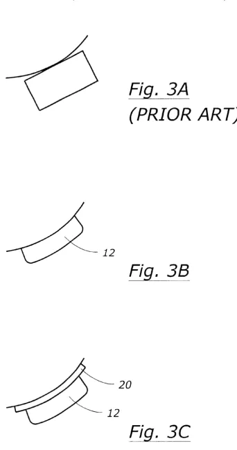
FIG. 3A is a diagram of a prior art bone conduction
sensor.
FIG. 3B is diagram of the bone conduction sensor of the present invention ?tted against a Wall of the external audi
tory canal.
FIG. 3C is a diagrammatic representation of the bone conduction sensor of the present invention including the
separation layer.
FIG. 4A is a diagram of the present invention Where tWo
contact sensors are in contact With the external auditory canal of the user.
FIG. 4B is a diagram of the present invention Where the
?rst of tWo contact sensors is in contact With the external auditory canal of a user.
FIG. 4C is a diagram Where the second of tWo contact
sensors is in contact With the external auditory canal of the
user.
FIG. 4D is a diagram Where a single contact sensor is used to determine Whether the bone conduction sensor is in contact With the external auditory canal of a user.
FIG. 5A is a diagram of a prior art bone conduction sensor
Where both the sensor element and the signal conditioning
are located Within the external auditory canal of the user.
FIG. 5B is a diagram of the present invention Where the bone sensor element is located adjacent the circuit portion of
the bone conduction sensor.
FIG. 5C is a diagram of the present invention Where the bone sensor element is located adjacent the circuit portion of
the bone conduction sensor in an alternative position.
FIG. 6 is a block diagram of the present invention.
DETAILED DESCRIPTION OF THE INVENTION
The present invention Will noW be described as it applies
to an exemplary embodiment. It is not intended that the
present invention be limited to the described embodiment. It
is intended that the invention cover all modi?cations and
alternatives Which may be included Within the spirit and scope of the invention.
The present invention is an apparatus and method for
improved bone conduction sensing. In particular, for
improved bone conduction sensing siZed and shaped to
nonocclusively ?t Within an external auditory canal of the
user and for use With voice sound sensing.
FIG. 1 is a diagram of a voice sound transmitting device 10 of the present invention. The device includes an improved bone conduction sensor 12. In addition, the device includes an air conduction microphone 14 and a speaker 16 all Within device 10 Which is adapted to be nonocclusively positioned Within the external auditory canal of a user.
The bone conduction sensor 12 may be any number of
types of sensors capable of vibration measurement. For
example, the bone conduction sensor 12 may include an
10 15 25 35 40 45 55 65
4
accelerometer, such as a pieZoelectric accelerometer. Tests have shoWn that a pieZoelectric accelerometer is capable of sensing the desired vibrations. Alternatively, a quartZ sens
ing element may be used, and other types of sensing elements capable of adaptation for sensing bone conduction
vibrations. The present invention is in no Way limited to a
particular type of vibration sensing.
FIG. 2 provides pictorial representation of the earpiece 10
of the present device positioned Within the ear of a user. The
bone conduction sensor 12 is positioned adjacent the pos
terior superior Wall of the external auditory canal 18.
Although the present invention is in no Way limited to this
particular placement of the bone sensor, this placement of
the bone conduction sensor 12 provides for improved sens ing of vibrations associated With the mastoid bone.
The present invention provides for the bone conduction
sensor of the earpiece 10 to have an improved shape. FIG. 3A shoWs the shape of a prior art bone conduction sensor.
FIG. 3B shoWs an improved bone conduction sensor. The
improved bone conduction sensor is shaped to more closely
?t or contour a Wall of the external auditory canal, such as
the posterior superior Wall. The ?t of the bone conduction
sensor 12 increases the amount of surface area contact
betWeen a sensing element Within the bone conduction sensor and the Wall of the external auditory canal. This increased surface area results in improved operation of the
sensor as the quality of the transmitted vibrations that are
received is improved. In addition, the Width of the bone
conduction sensor protruding into the external auditory canal is reduced permitting an earpiece to be smaller in siZe
and more nonocclusive. This results in a number of advan
tages including improved quality of the air conduction
signal, improved quality of output from a speaker disposed
Within the external auditory canal, increased comfort for a user, and reduced likelihood of displacement of the boneconduction sensor.
FIG. 3C discloses the bone conduction sensor 12 of the
present invention With a separation layer 20. The separation
layer 20 may be a ?lm or screen or other barrier. The
separation layer is silicone, rubber or plastic or other mate
rial that permits transmission of vibrations. The separation
layer is attached to the bone conduction sensor and is adapted to be ?tted directly to the Wall of the external
auditory canal. The separation layer is capable of conveying
vibrations at the Wall to the bone conduction sensor. The
separation layer 20 provides advantages of improved vibra
tions received at the bone conduction sensor While still
maintaining separation. The separation layer alloWs the
effective surface area for bone vibration pickup to beincreased When the separation layer extends beyond the bone conduction sensor itself. The separation layer is pref
erably an electrically insulating material. This provides
several advantages. One advantage is in the bone sensing.
The body of a user can give off electrical impulses that can
affect the operation of the bone conduction sensor. Although
signal spikes and other effects of these electrical impulses can be compensated for in signal processing, the separation
layer also serves to eliminate the effect of these electrical impulses. This separation layer can also protect the user
from the effects of an electrical impulse generated by the
bone conduction sensor. This separation layer also can result
in a more comfortable ?t for a user and can make a
contoured bone conduction sensor more easily custom ?t to
a user’s external auditory canal While still maintaining a
snug ?t betWeen the bone conduction sensor and the external
auditory canal of a user for improved sensor pickup.
FIGS. 4A through 4C illustrate a contact sensor of the
US 6,754,358 B1
5
When the bone conduction sensor becomes dislodged or
displaced, particularly in the context of the earpiece of the present invention. To monitor the placement or displacement
of the bone conduction sensor 12, one or more contact
sensors may be used. The present invention contemplates that the contact sensors may be contact sWitches, proximity
sensors, pressure sensors, or other sensors capable of deter
mining Whether all or a portion of the bone conduction
sensor 12 is in contact With a Wall of the external auditory canal or to What extent the bone conduction sensor 12 is in
contact With the Wall of the external auditory canal. As
shoWn, the bone conduction sensor 12 is associated With a
contact sensor 22A and a contact sensor 22B. The contact
sensors 22A and 22B contact an external Wall of the auditory canal. In FIG. 4B, the bone conduction sensor With contact
sensors is shoWn Where contact sensor 22A is not in contact
With the Wall of the external auditory canal Whereas sensor 22B is in contact With the Wall of the external auditory canal. Conversely, in FIG. 4C, contact sensor 22A is in contact With the Wall of the external auditory canal While contact
sensor 22B is not in contact With the Wall of the external
auditory canal. By monitoring the contact sensors 22A and 22B, it is determined Whether or not the bone conduction
sensor 12 has become displaced or dislodged. When one or
more of the contact sensors are not in contact With the
external Wall of the auditory canal, then it is knoWn that displacement has occurred. The present invention provides
for compensation for displacement by altering the sound
processing algorithm used by a processor in a voice soundtransmission device. For example, Where both an air con
duction sensor and a bone conduction sensor are used, the
signal received from the air conduction sensor may be more
heavily relied upon including solely relied upon once it is
knoWn that the bone conduction sensor is displaced and may
not be providing the desired signal. For example, if neither
contact sensor 22A nor 22B is in contact With the external
auditory canal, then the air conduction sensor can be relied upon exclusively. Alternatively, When one of the tWo contact
sensors indicate there is contact, but the other contact sensor
indicates that there is not, then the bone conduction sensor
may be partially relied upon. When both contact sensors are
indicating contact, then the bone conduction sensor may be
considered to be functioning properly and normal processing
can occur. The amount of force or pressure required to
indicate that the bone conduction sensor is in contact With
the external auditory canal may be dependent upon the siZe, shape, and Weight of the bone conduction sensor. HoWever,
it has been found that the current bone conduction sensor
requires only about 0.2 grams of contact Weighting When in
full contact With an external auditory canal Wall for optimal function.
The present invention also provides for a single contact
sensor to be used as shoWn in FIG. 4D. In FIG. 4D, the contact sensor 22 is located at a central point With respect to
the bone conduction 12, hoWever, the present invention
contemplates that the contact sensor 22 may be located at
other points, including at either end of the bone conduction
sensor 12.
In FIG. 5A and 5B, additional improvement of the present invention is disclosed. The present invention contemplates
separating a bone conduction sensor into a bone sensor
element 24 and a circuit portion. The circuit portion may be, but it not limited to a signal conditioning portion 26. The
present invention contemplates that the circuit portion may contain other circuitry, including poWer conditioning, or
other circuitry such as may be required or desirable for proper function of the bone sensing element Within the
10 15 25 35 40 45 55 65
6
context of a particular use and/or device. As shoWn in FIG.
5B, the signal conditioning portion 26 may be remotely
located or otherWise physically separated from the bonesensor element 24. The present invention further contem
plates that the circuit portion may be located remotely in the
behind the ear portion of an earpiece or other location that
need not be immediately adjacent the bone conduction
sensor. This provides an improvement in an earpiece of the present invention in that the siZe of that portion of the
earpiece Which extends into the external auditory canal of
the user is reduced. The resulting earpiece is nonocclusive to
a greater degree, improving the voice sound quality of the
earpiece device.
FIG. 5C illustrates that the signal conditioning portion of
the bone conduction sensor may be placed adjacent to the bone sensor element in a side-by-side con?guration. This position is advantageous over the bone sensor of FIG. 12 in that it reduces the amount of intrusion into the external
auditory canal. The present invention contemplates other
placements of the signal conditioning portion of the bone
conduction sensor adjacent to and remote from the bone
sensor element.
FIG. 6 is a block diagram of the present invention. In FIG.
6 both an air conduction sensor 14 and a bone conduction sensor 12 are electrically connected to a processor 28. The bone conduction sensor 12 is an improved bone conduction
sensor of the present invention. A speaker 16 may also be electrically connected to the processor 28. A transmitter 30
is electrically connected to the processor 28 as is a receiver
32. The transmitter 30 and receiver 32 may be respective portions of a transceiver 34. The processor 28, transmitter 30 and receiver 32 may be located Within the housing of the
earpiece 10.
The processor 28 may receive both an air conduction signal from the air conduction sensor 14 and a bone con
duction signal from the bone conduction sensor 12. In
addition the processor can receive a signal from a contact
sensor. In this manner the processor 28 can determine an
algorithm to apply to the received signals. For example, if
contact sensor 22 indicates that the bone conduction sensor
12 is not in proper position for bone conduction sensing of voice sound information, then the processor 28 can rely upon the signal from the air conduction sensor 14. In this manner, the processor 28 can compensate for displacement
of the bone conduction sensor 12.
It should be apparent that the present invention contem plates numerous variations in the materials used for the ?lm barrier, placement of the pressure sensors, the number of
pressure sensors, the location of the signal conditioning
circuitry of the bone conduction sensor, and other variations. These and other variations are Within the spirit and scope of
the invention noW claimed.
What is claimed is:
1. Abone conduction sensor for placement in an external
auditory canal comprising:
a bone sensing element having a contoured surface adapted to ?t against a Wall of the external auditory canal increasing the surface area contact betWeen the
sensing element and the Wall of the external auditory
canal;
at least one contact sensor adjacent the bone sensing
element for determining contact betWeen the bone
sensing element and the external auditory canal; and a circuit portion electrically connected to the sensing
element and the at least one contact sensor for deter
US 6,754,358 B1
7
position and compensating for the position of the bone sensing element When not in proper position.
2. The bone conduction sensor of claim 1 Wherein the
circuit portion is physically adjacent the bone-sensing ele
rnent.
3. The bone conduction sensor of claim 1 Wherein the
bone sensing element is a pieZoelectric element.
4. The bone conduction sensor of claim 1 Wherein the
bone sensing element is adapted to ?t against the posterior superior Wall of the external auditory canal.
5. An earpiece for nonocclusive placement in an external
auditory canal comprising:
a housing;
a bone conduction sensor mounted to the housing for
nonocclusive placement in the auditory canal having a
contoured surface adapted to ?t against a Wall of the
external auditory canal increasing a surface area con tact betWeen the bone conduction sensor and the Wall of
the external auditory canal;
an air conduction sensor adapted for nonocclusive place
rnent in the auditory canal mounted in the housing;
at least one contact sensor adjacent the bone conduction sensor for determining contact betWeen the bone con
duction sensor and the Wall of the external auditory
canal;
a circuit portion disposed Within the earpiece and electri
cally connected to the bone conduction sensor, the air
conduction sensor, and the at least one contact sensor;
and
the circuit portion adapted for determining Whether the
bone conduction sensor is in proper position based on
a state of the at least one contact sensor.
6. The earpiece of claim 5 Wherein the at least one contact
sensor includes a ?rst contact sensor and a second contact
sensor arnounted adjacent the bone conduction sensor.
10
3O
35
8
7. The earpiece of claim 5 further comprising a separation
layer attached to the bone conduction sensor and adapted to be ?tted directly to the Wall of the external auditory canal and capable of conveying vibrations at the Wall to the bone
conduction sensor.
8. The earpiece of claim 7 Wherein the separation layer
comprises a material selected from the set including rubber,
plastic, ?lrn, rnetal ?lrns silicone, and an electrical insulator. 9. The earpiece of claim 7 Wherein the separation layer
has a surface area adapted for contacting the Wall of the external auditory canal greater in siZe than the surface area
contact of the bone conduction sensor.
10. The earpiece of claim 5 further comprising a sound processor electrically connected to the bone conduction
sensor and the air conduction sensor and disposed Within the
housing.
11. The earpiece of claim 5 further comprising a processor electrically connected to the bone conduction sensor and the air conduction sensor and disposed Within the housing; and
the at least one contact sensor electrically connected to the processor.
12. A method of bone conduction sensing cornprising:
transmitting a bone conduction vibration signal at a Wall of the external auditory canal through an insulative
conductive layer;
sensing a bone conduction vibration signal at the insula
tive conductive layer With a sensing element; conveying the sensed bone conduction signal to a position
removed from the external auditory canal;
monitoring the position of the bone sensing element using
at least one contact sensor;