Multizone Internal Combustion Engine Modelling
Initial Assessment of
Abstract—A multizone model for the thermodynamic simulation of internal combustion engines has been developed.
multizone model differs from earlier, related formulations in a number of important respects. A number of zones,
and unburned, can be tracked throughout the entire simulation. Heat transfer areas for burned and unburned zones can be specified as a function of engine geometry. Leakage of gas past piston rings can be simulated using a flow rate model
pressure differences. Furthermore, the injection of fuel during the compression stroke and charge stratification across the zones can also be simulated. In this paper, an overview of some of these features is provided. An initial assessment of
temperatures, and NO concentrations derived from
also performed by comparing results obtained from the present modeling with results from two earlier simulations.
Keywords – internal combustion engine simulation
I. INTRODUCTION
Thermodynamic simulation of internal combustion engines is likely to continue to make a contribution to the development of our understanding of new and existing configurations for the foreseeable future. Within the context of university research activities, having a simulation tool that is openly
both undergraduate and postgraduate students is very desirable. Existing tools for the thermodynamic simulation of internal combustion engines do not generally meet this requirement source code may not be open access, or the program may be written in a computing language with which students are not generally familiar. In the original edition of the work by Ferguson [1], Fortran programs that could be used in the simulation of internal combustion engines
However, the second edition (2001) of Ferguson’s work does not list the Fortran source.
At the present time, Matlab appears to be the preferred technical computing environment for a significant proportion of undergraduate science and engineering programs.
translations of Ferguson’s original Fortran programs made available to the international community in 2002 since that time, a number of students and academics accessed and used the Matlab version.
The purpose of the current paper is to introduce a number of improvements to the original modelling which should make the Matlab engine simulations more appealing as a research tool. These improvements include the addition of multizone modeling, a pressure-driven leakage model, and a module for
Multizone Internal Combustion Engine Modelling
Initial Assessment of a Simulation Tool Developed in Matlab
David Buttsworth
Faculty of Engineering and Surveying University of Southern Queensland
Toowoomba, Australia
A multizone model for the thermodynamic simulation of internal combustion engines has been developed. The new, multizone model differs from earlier, related formulations in a number of important respects. A number of zones, both burned and unburned, can be tracked throughout the entire simulation. Heat transfer areas for burned and unburned zones can be specified as a function of engine geometry. Leakage of gas past a flow rate model driven by Furthermore, the injection of fuel during the compression stroke and charge stratification across the zones In this paper, an overview of some of these An initial assessment of the pressures, temperatures, and NO concentrations derived from the model is obtained from the present two earlier simulations.
simulation
modynamic simulation of internal combustion engines is likely to continue to make a contribution to the development of our understanding of new and existing configurations for the future. Within the context of university research openly accessible to both undergraduate and postgraduate students is very desirable. Existing tools for the thermodynamic simulation of internal combustion engines do not generally meet this requirement: the be open access, or the program may be with which students are not n the original edition of the work by programs that could be used in the simulation of internal combustion engines were published.
of Ferguson’s work does
appears to be the preferred for a significant proportion of undergraduate science and engineering programs. Matlab translations of Ferguson’s original Fortran programs [1] were made available to the international community in 2002 [2] and students and academics have
of the current paper is to introduce a number of improvements to the original modelling which should make the Matlab engine simulations more appealing as a research e improvements include the addition of multizone driven leakage model, and a module for
the thermal formation of nitric oxide.
includes the capacity to model fuel injection during the compression stroke and the co
however, this feature will not be described in further detail in the present work.) As was the case with the original version, the intention is to make the Matlab source freely available on the internet as an option for the
within the academic community.
II. M
A. Multizone Formulation
The multizone arrangement we are considering is illu in Fig. 1. In this figure, the flame is illustrated within the second zone from the spark plug, but
i, a general zone index within a total number of zones, the flame reaches zone i, the zone is broken into unburned ( and burned (bi) components. T
zone i until all of the unburned charge is combustion products, after which burning begins in zone
[image:1.595.356.500.516.655.2]At present, the rate of burning is governed by a ‘burn law’ rather than simulated using a turbulent flame propa model. Cosine and Weibe functions can be prescribed for the burn law. Alternatively, experimental data on the burning derived from in-cylinder pressure measurements at fixed crank angles can be specified and a spline will be fitted to the experimental data for the burn progress
Figure 1. Illustration of zones in the engine modelling.
Future versions of the code may include the addition of a turbulent flame propagation model. While this would make a useful addition, the utility of the program may not be greatly
Multizone Internal Combustion Engine Modelling:
Simulation Tool Developed in Matlab
the thermal formation of nitric oxide. (The new version also includes the capacity to model fuel injection during the compression stroke and the combustion of a stratified charge, however, this feature will not be described in further detail in As was the case with the original version, the intention is to make the Matlab source freely available on the internet as an option for the teaching and research work within the academic community.
MODELLING
The multizone arrangement we are considering is illustrated In this figure, the flame is illustrated within the second zone from the spark plug, but this zone is designated as , a general zone index within a total number of zones, n. When , the zone is broken into unburned (ui), ) components. The flame propagates through until all of the unburned charge is converted to , after which burning begins in zone i+1. At present, the rate of burning is governed by a ‘burn law’
using a turbulent flame propagation functions can be prescribed for the burn law. Alternatively, experimental data on the burning cylinder pressure measurements at fixed crank angles can be specified and a spline will be fitted to the experimental data for the burn progress.
Illustration of zones in the engine modelling.
enhanced with this feature. The current ‘burn laws’ have parameters that can be adjusted, within reasonable limits, until the simulations produce some observed characteristics of the actual engine. The addition of a turbulent flame propagation model will introduce alternative parameters that do not necessarily have known values for the engine or configuration of interest. Thus, the introduction of a tur
propagation model is seen as largely shifting the modeling from one set of parameters to anothe
B. Leakage
In the original version of the routines, the leakage of ga past the piston rings was modeled using a
approach [1]. In the current version, leakage can be modeled using the pressure difference between the combustion chamber, a crevice between the rings, and the crank case, F
that leaks from the cylinder into the crevice is assumed to come from the unburned zone of the last zone in the cylinder.
The crank case is treated as an infinite plenum and hence its pressure is a specified value and it does not change during the cycle. However, the initial conditions within the crevice need to be specified for simulation to proceed. The flow rate of gas into the crevice from the cylinder (combustion chamber), and the flow rate of gas from the crevice into the crank case are determined from the pressure difference
assumed throat areas, which separate the 3 volumes
During the expansion stroke, the pressure in the crevice can be larger than the cylinder pressure so the flow direction is reversed under these conditions.
[image:2.595.341.520.357.552.2]Cylinder leakage generally has a small impact on the simulated cylinder pressures and temperatures in a production engine. However, the introduction of a more realistic model for the leakage process in the present work is seen as a positive step, particularly for the future simulation of unburned hydrocarbon emissions associated with crevice volumes. Furthermore, the new leakage model should be of some use the simulation of optical research engines, which can have substantially more leakage than production engines.
Figure 2. Illustration of the pressure-driven leakage model
C. NO formation
A model for thermal formation of nitric oxide has also been introduced in the present modeling. The extended
mechanism has been adopted. For this modeling, the rate of formation of NO is determined based on specified rate constants and the equilibrium temperatures and concentrations . The current ‘burn laws’ have parameters that can be adjusted, within reasonable limits, until observed characteristics of the turbulent flame propagation ve parameters that do not necessarily have known values for the engine or configuration introduction of a turbulent flame propagation model is seen as largely shifting the uncertainty in
from one set of parameters to another.
the routines, the leakage of gas past the piston rings was modeled using a rate constant approach [1]. In the current version, leakage can be modeled using the pressure difference between the combustion chamber, the rings, and the crank case, Fig. 2. The gas that leaks from the cylinder into the crevice is assumed to come from the unburned zone of the last zone in the cylinder.
The crank case is treated as an infinite plenum and hence its and it does not change during the cycle. However, the initial conditions within the crevice need to be specified for simulation to proceed. The flow rate of gas into the crevice from the cylinder (combustion chamber), and te of gas from the crevice into the crank case are across the two assumed throat areas, which separate the 3 volumes, Fig. 2.
n the crevice can be pressure so the flow direction is
Cylinder leakage generally has a small impact on the simulated cylinder pressures and temperatures in a production engine. However, the introduction of a more realistic model ge process in the present work is seen as a positive step, particularly for the future simulation of unburned hydrocarbon emissions associated with crevice volumes.
the new leakage model should be of some use for earch engines, which can have than production engines.
driven leakage model.
thermal formation of nitric oxide has also been extended Zeldovich modeling, the rate of formation of NO is determined based on specified rate constants and the equilibrium temperatures and concentrations
of the key species. Raine et al. [3] have reviewed thermal formation of nitric oxide rate constants in the context of internal combustion engines from various sources. Options for using the rate constants suggested
Borman and Ragland [5] are available in the routine. Equilibrium compositions are obtained using the method of Olikara and Borman [6] as described by Ferguson [1].
D. Implementation
The modeling was implemented in the Matlab environment The nonlinear ordinary differential equatio
problem were integrated from i
assumed to apply from inlet valve closure at centre using the Matlab function ‘ode23’.
III. SINGLE
As a demonstration that the basic elements of the are working satisfactorily, results from the new,
formulation are compared with results from simulations using the earlier, single zone formulation [2]. In the present case, the multizone formulation is run with a single burned zone in order to produce results that are directly comparable to th
[image:2.595.111.224.486.625.2]formulation. The chosen test case is that presented by Ferguson [1] with the key simulation parameters listed in Table I.
TABLE I. ENGINE SIMULATION PAR COMPARISON WITH RESU
Parameter
Fuel
Equivalence ratio
Bore
Stroke
Connecting rod length
Compression ratio Blowby constant Residual fraction Speed Initial pressure Initial temperature
For these simulations, a cosine burn the start of burning specified as the burn duration specified as
Ferguson [1], heat transfer with constant heat transfer coefficients in the burned and
was considered. However, since the new, multizone formulation does not currently treat the cylinder areas available for heat transfer in the same way as the original Ferguson formulation, it was decided to perform an adiabatic simulation using [2] for direct comparison.
Results from these simulations are presented in Figs. 3 and 4. Pressure and temperature levels obtained in the new, multizone formulation (when run using a single burned zone) key species. Raine et al. [3] have reviewed thermal ormation of nitric oxide rate constants in the context of internal combustion engines from various sources. Options for suggested by either Heywood [4] or [5] are available in the routine.
are obtained using the method of Olikara and Borman [6] as described by Ferguson [1].
The modeling was implemented in the Matlab environment. The nonlinear ordinary differential equations which govern the
from initial conditions which were assumed to apply from inlet valve closure at bottom dead
using the Matlab function ‘ode23’.
INGLE ZONE RESULTS
As a demonstration that the basic elements of the program results from the new, multizone formulation are compared with results from simulations using the earlier, single zone formulation [2]. In the present case, the multizone formulation is run with a single burned zone in order to produce results that are directly comparable to the earlier formulation. The chosen test case is that presented by Ferguson [1] with the key simulation parameters listed in Table
NGINE SIMULATION PARAMETERS ADOPTED FOR COMPARISON WITH RESULTS OF FERGUSON [1]
Value Gasoline 0.8 0.1 m 0.08 m 0.16 m 10
0.8 s-1
0.1
2000 rpm
100 kPa
350 K
osine burning law was used with the start of burning specified as 35º before top dead centre and the burn duration specified as 60º. In the original case of Ferguson [1], heat transfer with constant heat transfer coefficients in the burned and unburned zones of 500 W/m2K considered. However, since the new, multizone formulation does not currently treat the cylinder areas available for heat transfer in the same way as the original Ferguson formulation, it was decided to perform an adiabatic simulation
or direct comparison.
are virtually identical to those obtained from the earlier model [2]. The differences between the present simulations and the earlier simulations presented by Ferguson [1], that are particularly noticeable for the burned zone temperatures, arise because the present simulation is for the adiabatic case.
[image:3.595.321.544.175.572.2]Figure 3. Pressures in Ferguson [1] test case. Comparison of earlier single zone formulation [2] with current multizone formulation for adiabitic case.
Figure 4. Temperatures in Ferguson [1] test case. Comparison of earlier single zone formulation [2] with current multizone formulation for adiabitic
conditions.
IV. NOFORMATION RESULTS
To exercise the modeling of nitric oxide formation, a case from the work of Raine et al. [3] is considered. The key simulation parameters are presented in Table II. For these simulations, a Weibe function with the start of combustion specified as 12º before top dead centre and a burn duration specified as 30º have been used. In the work of [3], the effective inlet valve closure was specified as 15º past bottom dead centre, but for convenience, integration in the present work was started at bottom dead centre. The results of [3] considered in the present section are for a single zone, adiabatic case. The rate constants suggested by Heywood [4] were adopted for the present simulations and for those of [3].
Results from the present simulations are compared with the simulations of [3] in Figs. 5 to 7. There is generally good agreement between the results of Raine et al. [3] and the present modeling. Note that the results of Raine et al. were digitized from the plots presents in the paper [3] and thus some difference between the results of Raine et al. and the present simulations should be expected because of inaccuracies in the conversion process.
TABLE II. ENGINE SIMULATION PARAMETERS ADOPTED FOR COMPARISON WITH RESULTS OF RAINE ET AL.[3]
Parameter Value
Fuel Methane
Equivalence ratio 1.0
Bore 0.107 m
Stroke 0.115 m
Connecting rod length 0.203 m
Compression ratio 14.7
Blowby constant 0.8 s-1
Residual fraction 0.09
Speed 1500 rpm
Initial pressure 90 kPa
Initial temperature 350 K
Figure 5. Pressures in Raine et al. [3] test case. Comparison of single zone results of Raine et al. [3] with current results.
[image:3.595.43.278.347.524.2]Although the temperatures simulated in the present work appear slightly high relative to the values of [3], the initial development of NO concentrations in the present simulations appear to lag those of [3] (Fig. 7). However, the peak and final concentration values are in close agreement between the two simulations, Fig. 7.
Figure 6. Temperatures in Raine et al. [3] test case. Comparison of single zone results of Raine et al. [3] with current results.
Figure 7. NO concentrations in Raine et al. [3] test case. Comparison of single zone results of Raine et al. [3] with current results.
V. MULTIZONE RESULTS
Raine et al. [3] have also presented simulations results for a 5 zone adiabatic case corresponding to the conditions listed in Table II, and discussed in section IV. Simulation of this 5 zone case was also performed for the present work to exercise the multizone capabilities of the new routine. Results from these simulations are presented in Fig. 8 to 11.
There is good agreement between the two simulations in terms of the pressures (Fig. 8) and temperatures (Fig. 9). The agreement between the simulations for the NO concentrations in zones 1, 3, and 5 is generally good, although the present results for zone 5 are about 20% low relative to the simulation
[image:4.595.42.279.135.312.2]of [3]. The phasing of the initial growth in nitric oxide concentration in zones 1 and 5 of the present simulations closely follows that of [3].
[image:4.595.312.546.322.502.2]Figure 8. Pressures in Raine et al. [3] test case. Comparison of five zone simulation of Raine et al. [3] with current results.
Figure 9. Temperatures in Raine et al. [3] test case. Comparison of five zone simulation of Raine et al. [3] with current results for zones 1, 3, and 5.
Fig. 11 presents the NO concentration averaged over all zones. These results demonstrate a good level of agreement between the present simulations and those of [3]. The net NO concentration at the end of the expansion stroke simulated with the 5 zone model is about 3000 ppm for the present conditions whereas for the single zone model, the concentration is about 10% higher, consistent with the previous simulations of [3].
[image:4.595.43.278.355.535.2]the NO formation because the governing chemistry models have an exponential temperature dependence.
Figure 10. NO concentrations in Raine et al. [3] test case. Comparison of five zone simulation of Raine et al. [3] with current results for zones 1, 3, and 5.
Figure 11. NO concentrations in Raine et al. [3] test case. Comparison of five zone simulation of Raine et al. [3] with current results for net NO
concentration across the 5 zones.
VI. SUMMARY AND CONCLUSIONS
Certain elements of a new multizone thermodynamic tool for the simulation of internal combustion engines have been described in the present work. The tool has been developed in the Matlab environment, and it offers a number of new features relative to an earlier version which has been used by a number of students and academics for the simulation of internal combustion engines. In particular, the new model offers the capacity to simulate a number of zones which should improve accuracy in modeling nitric oxide formation and other effects such as heat transfer that are sensitive to spatial location.
The performance of the new modeling is assessed by comparing present results to those produced by other programs. Pressures, temperatures and nitric oxide concentrations produced by the present modeling are shown to be in good agreement with the simulated results produced by other programs. It is concluded that the formulation of the multizone model, the model for the thermal formation of nitric oxide, and their implementation in the Matlab environment are sound.
Further work is required to validate the modeling of features that have not been discussed in detail in the present publication. These features include: leakage, direct fuel injection during the compression stroke, and the combustion of a stratified charge.
REFERENCES
[1] C. R. Ferguson, Internal Combustion Engines, Applied Thermosciences, John Wiley and Sons, New York, 1986.
[2] D. R. Buttsworth, “Spark Ignition Internal Combustion Engine Modelling using Matlab,” Faculty of Engineering and Surveying Technical Reports, TR-2002-02, University of Southern Queensland, 2002.
[3] R. R. Raine, C. R. Stone, J. Gould, “Modeling of Nitric Oxide Formation in Spark Ignition Engines with a Multizone Burned Gas,” Combustion and Flame, vol. 102, 241–255, 1995.
[4] J. B. Heywood, “Internal Combustion Engine Fundamentals,” McGraw-Hill, New York, 1988
[5] G. L. Borman, K. W. Ragland, “Combustion Engineering,” McGraw-Hill, New York, 1998.
[image:5.595.41.278.92.270.2] [image:5.595.42.277.313.491.2]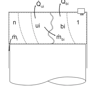
![TABLE I. ENGINE SIMULATION PARCOMPARISON WITH RESUNGINE SIMULATION PARAMETERS ADOPTED FOR COMPARISON WITH RESULTS OF FERGUSON [1]](https://thumb-us.123doks.com/thumbv2/123dok_us/191801.54769/2.595.111.224.486.625/simulation-parcomparison-resungine-simulation-parameters-adopted-comparison-ferguson.webp)
![Figure 8. Pressures in Raine et al. [3] test case. Comparison of five zone simulation of Raine et al](https://thumb-us.123doks.com/thumbv2/123dok_us/191801.54769/4.595.42.279.135.312/figure-pressures-raine-test-case-comparison-simulation-raine.webp)
![Figure 10. NO concentrations in Raine et al. [3] test case. Comparison of five zone simulation of Raine et al](https://thumb-us.123doks.com/thumbv2/123dok_us/191801.54769/5.595.42.277.313.491/figure-concentrations-raine-test-case-comparison-simulation-raine.webp)
